Page 805 of 2189

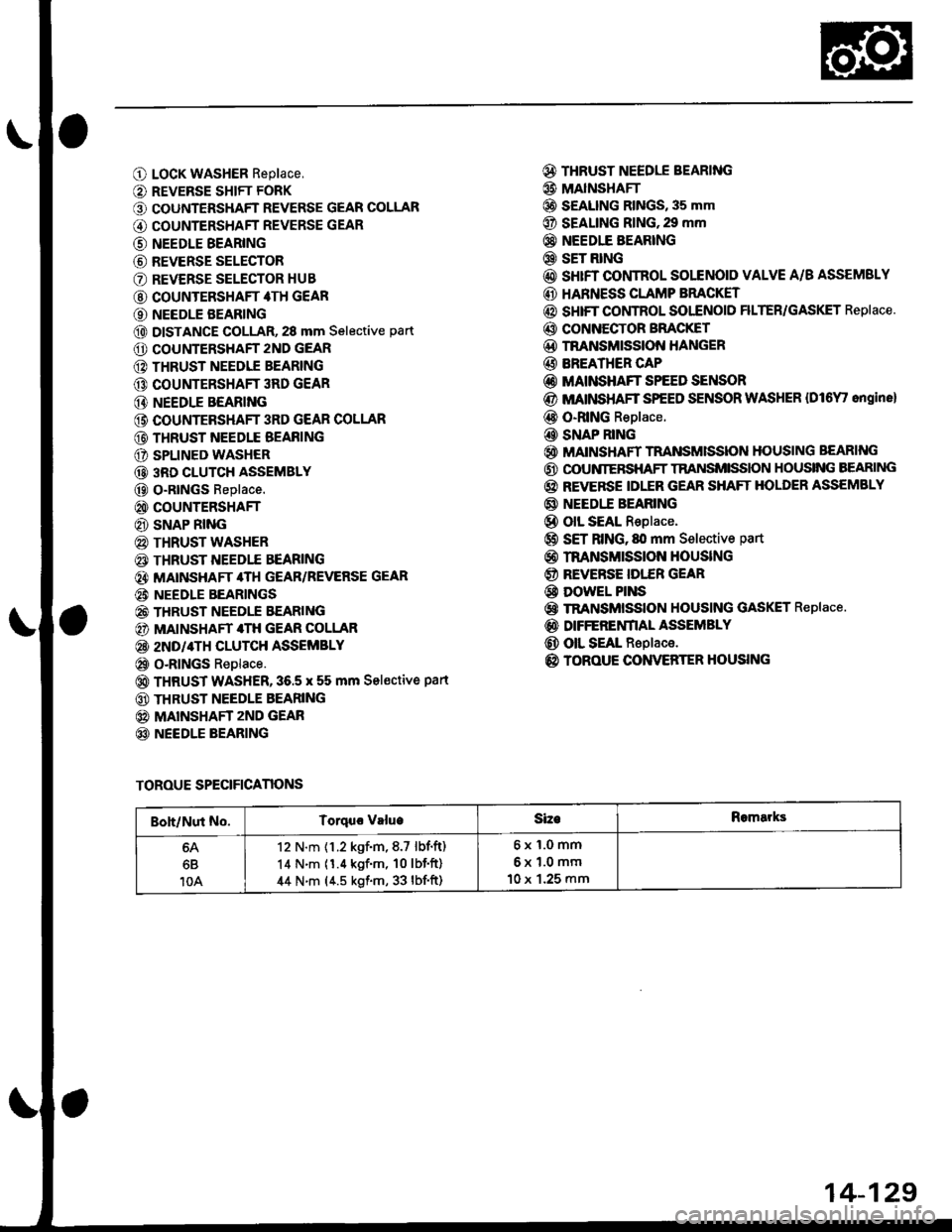
O ROLLER
O COLLAR
O o-RING Replace.
@ FEED PIPE FLANGE
@ O-RING Replace.
@ SNAP RING
€) 3RD CLUTCH FEED PIPE
€) COUNTERSHAFT LOCKNUT (FLANGE NUT)
23 x 1.25 mm Replace.
o coNlcAL SPRING WASHER Replace.
@ PARK GEAR
@ ONE.WAY CLUTCH
@ COUNTERSHAFT lST GEAR
@ NEEDLE BEARING
@ COUNTERSHAFT lST GEAR COLLAR
@ o-RlNGs Replace.
@ END covER GASKET Replace.
E) DOWEL PINS
@ PARK PAWL STOP
@ LocK WASHER Replace.
@ PARK STOP Selective part
€D PARK LEVER
@ PARK LEVER SPRING
€D DRAIN PLUG
€) SEALING WASHER Replace
@ o-RING Replace.
@ COUNTERSHAFT SPEED SENSOR
@) PARK PAWL
@ PARK PAWL SPRING
@ PARK PAWL SHAFT
@ LINEAR SOLENOID ASSEMBLY
@ LINEAR SOLENOID GASKET REPIACE.
@) END COVER
@ lsT CLUTCH FEED PIPE
@ O-RINGS Replace.
@ FEED PIPE FLANGE
C) SNAP BING
@ MAINSHAFT LOCKNUT (FLANGE NUTI 21 x 1 25 mm
Replace.
@ CONICAL SPRING WASHER RePlace
@) lST CLUTCH ASSEMBLY
@ o-RlNGs Replace.
€) THRUST WASHER
@) THRUST NEEDLE BEARING
@ NEEDLE BEARING
@ MAINSHAFT lST GEAR
@ MAINSHAFT lST GEAR COLLAR
@) ATF COOLER LINE
@ SEAUNG WASHERS Replace.
@ LINE BOLT
@ ATF DIFSTICK
@ ATF COOLER LINE
@ UNE BOLT
@ SEALING WASHERS Replace.
@ VEHICTT SPEED SENSOR
@ O-RING Replace.
TOROUE SPECIFICATIONS
Bolt/Nut No.Torque ValueSizeRemarks
6B
8F
12A.'l8D
2'tM
23C
'12 N'm (1.2 kgim,8.7 lbift)
14 N.m (1.4 kgf.m, 10 lbf'ft)
22 N.m (2.2 kgf.m, 16 lbf'ft)
28 N.m (2.9 kgf.m, 21 lbf'ft)
49 N.m (5.0 kgf.m, 36 lbf'ft)
78 N.m (8.0 kgf'm, 58 lbf'ft)
103 N.m {10.5 kgf'm,75.9 lbift)
6x1.0mm
6x1.0mm
8 x 1,25 mm
12 x 1.25 mm
18 x 1.5 mm
21 x 1.25 mm
23 x 1.25 mm
Line bolt
Drain plug
Mainshatt locknut: Left-hand threads
Countershaft locknut:
Left-hand threads
14-127
Page 807 of 2189

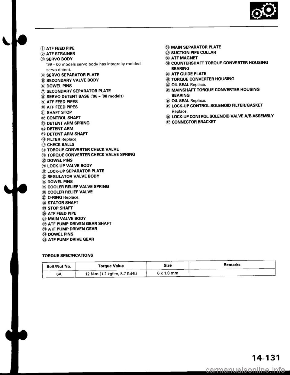
O LocK WASHER Replace,
O REVERSE SHIFT FORK
O COUNTERSHAFT REVERSE GEAR COLLAR
G) COUNTERSHAFT REVERSE GEAR
@ NEEDLE BEARING
@ REVERSE SELECTOR
O REVERSE SELECTOR HUB
@ COUNTERSHAFT 4TH GEAR
O NEEDLE BEARING
@ DISTANCE GOLLAR, 28 mm Selective part
O COUNTERSHAFT 2ND GEAR
@ THRUST NEEDIE BEARING
@ COUNTERSHAFT 3RD GEAR
@ NEEDLE BEARING
@ COUNTEBSHAFT 3RD GEAR COLLAR
@ THRUST NEEDLE BEAFING
O SPLINED WASHER
@ 3RD CLUTCH ASSEMBLY
@ O-RtNGs Replace.
@ COUNTERSHAFT
@ SNAP RING
@ THRUST WASHER
€) THRUST NEEDTE BEARING
@} MATNSHAFT 4TH GEAR/REVERSE GEAR
@i NEEDLE BEARINGS
@ THRUST NEEDLE EEARING
@) MAINSHAFT 4TH GEAR COLLAR
@ 2ND/4TH CLUTCH ASSEMBLY
@ o-RlNGs Replace.
@ THRUST WASHER,36.5 x 55 mm Sel€ctive part
@ THRUST NEEDLE BEARING
@ MAINSHAFT zND GEAR
@ NEEDLE BEARING
@ THRUST NEEDLE BEARING
@ MAINSHAFI
@ S€ALING RINGS, 35 mm
@ SEALING RING,29 mm
@} NEEDIE BEARING
@ SET RING
@ sHrFT CONTROL SOLENOID VALVE A/B ASSEMSLY
@ HARNESS CLAMP BRACKET
@ SHIFT COI,ITROL SOI"ENOID FILTER/GASKET Replace.
@ CONNECTOR BFACKET
@D TNANSMISSION HANGER
@ BREATHER CAP
@ MAINSHAFT SPEED SENSOR
@ MATNSHAFT SPEED SENSOR WASHER {Dl6Y' ongine}
@ O-RING Replace.
@ SNAP RING
@ MAINSHAFT TRANSMISSION HOUSING BEARING
@ OOUNIERSHAFT TRANSMISSION HOUSING BEARING
@ REVERSE IDLER GEAR SHAFT HOLDER ASSEMBLY
@ NEEDI.E BEARING
@ olL SEAL Replace.
@ SET RING, fll mm Selective part
@ rnANsMrssloN HouslNG
@ REVERSE IDI."ER GEAR
@ DowEL PINS
@ TRANSMISSION HOUSING GASKET Replace.
@ DIFFERENfIAL ASSEMBLY
@ OIL SEAL Replace.
@ TOROUE CONVERTER HOUSING
TOROUE SPECIFICANONS
Boh/Nut No.Torquo valueSizeRomarks
6B
10A
12 N.m {1.2 kgf.m,8.7 lbf.ft)
14 N.m (1.4 kgf'm, 10lbf'ft)
44 N.m (4.5 kgf.m, 33 lbf'ft)
6x1.0mm
6x1.0mm
10 x 1.25 mm
14-129
Page 809 of 2189

O ATF FEED PIPE
O ATF STRAINER
O SERVO BODY'99 - 00 models servo body has integrally molded
servo detent.
@ SERVO SEPARATOR PLATE
(' SECONDARY VALVE BODY
@ DOWEL P|NS
O SECONDARY SEPARATOR PLATE
@ SERVO DETENT BASE ('�96 -'98 models)
O ATF FEED PIPES
(D ATF FEED PIPES
O SHAFT STOP
@ CONTROL SHAFT
€D DETENT ARM SPRING
@ DETENT ARM
(9 DETENT ARM SHAFT
@ FILTER Replace.
(? CHECK BALLS
@ TOROUE CONVERTER CHECK VALVE
@ TOROUE CONVERTER CHECK VALVE SPRING
@ DOWEL PINS
@ LOCK.UP VALVE BODY
@ LOCK-UP SEPARATOR PLATE
@ REGULATOR VALVE BODY
@} DOWEL PINS
@ COOLER RELIEF VALVE SPRING
@ COOLER RELIEF VALVE
@ O-RING Replace.
@ STATOR SHAFT
@ STOP SHAFT
@ ATF FEED PIPE
@ MAIN VALVE BODY
@ ATF PUMP DRIVEN GEAR SHAFT
@ ATF PUMP DRIVEN GEAR
@ DOWEL PINS
65) ATF PUMP DRIVE GEAR
@ MAIN SEPARATOR PLATE
@ SUCTION PIPE COLLAR
@ ATF MAGNET
@ COUNTERSHAFT TOROUE CONVERTER HOUSING
BEARING
@ ATF GUIDE PLATE
@ ToRoUE CONVERTER HOUSING
@ OIL SEAL Replace.
@ MAINSHAFT TOROUE CONVERTER HOUSING
BEARING
@) olL SEAL Replace.
@ LOCK-UP CONTROL SOLENOID FILTER/GASKET
Reolace.
@ LOCK-UP CONIROL SOLENOID VALVE A/B ASSEMELY
@ CONNECTOR BRACKET
TOROUE SPECIFICANONS
Bolt/Nut No.Torque ValugSiz€Remarkg
12 N.m (1.2 kgf.m,8.7 lbnft)6x1,0mm
14-131
Page 810 of 2189
End Cover
Removal
NOTE:
. Cleanall parts thoroughly in solvent or carburetor cleaner, and drywith compressed air,. Blow out all passages,
. When removing the right side cover, replace the following:- O-rings- Mainshaft and countershaft locknuts- Conical spring washgrs- End cover gasket
- Lock washer- Sealing washers
END COVER6 x 1.0 mm BOLT13 Bolts
PARK PAWL
PARK ITVER
LOCK WASHER
COUI{TERSI{AFTLINE AOLT
tST GEAF COLLAR
I
14-132
SEALING WASHERS
Page 811 of 2189

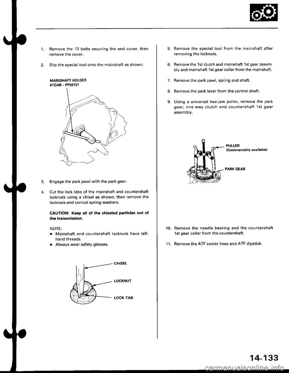
1.Remove the 13 bolts securing the end cover, then
remove the cover.
Slip the special tool onto the mainshaft as shown.
MAINSHAFT HOLOER
07GAB - PFs0101
Engage the park pawl with the park gear.
Cut the lock tabs of the mainshaft and countershaft
locknuts using a chisel as shown. then remove the
locknuts and conical spring washers
CAUTION: Keep all of lhe chiseled particles out of
the transmission.
NOTE:
. Mainshaft and countershaft locknuts have left-
hand threads.
. Always wear safety glasses.
4.
cHrs€L
LOCKNUT
LOCK TA8
5.
6.
11.
Remove the special tool from the mainshaft after
removing the locknuts.
Remove the 1st clutch and mainshaft 1st gear assem
bly and mainshaft 1st gear collar from the mainshaft.
7. Remove the park pawl. spring and shaft.
8. Remove the park lever from the control shaft.
9. Using a universal two-jaw puller, remove the park
gear, one way clutch and countershaft 1st gear
assemory.
PULLER(CommerciallY available)
PARK GEAR
10.Remove the needle bearing and the countershaft
1st gear collar from the countershaft
Remove the ATF cooler lines and ATF dipstick.
14-133
Page 812 of 2189
Transmission Housing
Removal
MAINSHAFT
TRANSMISSION HOUSINGMOUNTING BOLTS18 Bolts
TRANSMISSIONHANGERTRANSMISSION HOUSING
MAINSHAFTSUB.ASSEMBLY
SENSOR WASHERlD16Y7 engine)
MAINSHAFTSPEED SENSOR
TRANSMISSIONHOUSING GASKETDIFFEBENTIALASSEMBLY
TOROUE CONVERTERHOUSING
SUB.ASSEMBLY
L,
14-134
Page 814 of 2189
Torque Converter Housing/Valve Body
Removal
ATF FEEO PIP€
LOCK-UP VALVEBODY
PIN
6x1.0mm
LOCK-UP SEPARATORPLATE
REGULATORVALVE SODY
DOWEL PIN
COOLER RELIEF VAL
SERVO DETENTSTRAINER
SERVO EODY
SEPARATON
BASE
ATF FEEDPIPES
CONTROLSHAFT
DETENTARM SHAFT
DETENTARM
ATF FEED PIPE
6x1.0mm5 Eolts6x1.0mm3 Eolts
MAIN VALBODY
ATF PUMP
DRIVEN
VALVE BODY
PINGEAR SHAFT
ATF PUMP
MAIN SEPARAPLATE
SECONDARYSEPARATOR PLATE
NOTE: The illustration shows the '96 - 98 models, the '99 - 00 models do not have the servo detent base; the servo detentis integral with the servo body.
L
14-136
Page 815 of 2189

NOTE;
. Clean all parts thoroughly in solvent or carburetor
cleaner, and dry with compressed air.
. Blow out all passages.
. When removing the valve body, replace the O-ring.
l, Remove the ATF feed pipes from the servo body,
secondary valve body and main valve body.
For'96 - 98 models: Remove the ATF strainer and
servo detent base (two bolts).
For'99 - 00 models: Remove the ATF strainer (one
bolt).
Remove the servo body and servo separator plate
{'96 - 98 models: seven bolts,'99 - 00 models: eight
bolts).
Remove the secondary valve body, shaft stop and
secondary separator plate (three bolts).
Remove the lock-up valve body and separator plate
{seven bolts).
Remove the regulator valve body (one boltl.
Remove the stator shaft and stop shaft.
Remove the detent spring from the detent arm. then
remove the control shaft from the to.que converter
housing.
Remove the detent arm and detent arm shaft from
the main valve body.
Remove the main valve body (five bolts).
NOTE: Do not let the eight check balls fall outofthe
main valve body when removing the main valve
body.
Remove the ATF pump driven gear shaft, then remove
the ATF pump gears.
Remove the main separator plate and two dowel
pins.
7.
't'1.
10.
12.
14.
13. CIean the inlet opening of the ATF strainer thor-
oughly with compressed air. then check that it is in
good condition, and the inlet opening is not clogged.
INLET OPENING
Test the filter by pouring clean ATF fluid through
the inlet opening. Beplace the ATF strainer if it is
clogged or damaged.
NOTE: The ATF str8iner can be reused if it is not
clogged.
14-137