1998 HONDA CIVIC Short to ground
[x] Cancel search: Short to groundPage 1402 of 2189
Troubleshooting -'99 - 00 Models
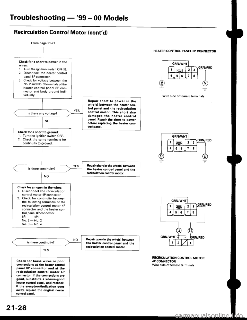
Recirculation Control Motor (cont'd)
Frcm page 21-27
HEATER CONTROL PANEL 8P CONNECTOR
Check for a short to power in the
1. Turn the ignition switch ON {ll).2. Disconnect the heater controlpanel 8P connector.3. Check for voltage between theNo.2 and No. 3 terminals oftheheater control panel 8P con,nector and body ground individually.
Repair 3hort to powe. in thewire{a) b.tween tho haetor con-trol panel and the recirculationGontrol moto.. This short alsodamagos the heate. controlpanel. Repair the short to powerb€tore .eplecing the h€ater con-trol panel.
ls there any voltage?
Check to. a short to ground:1. Turn the ignition switch OFF.2- Check the same terminals forcontinuity to ground.
Roprir lhon in tho wir.{s) b€tweothe horter control panel and theracircr alion conhol motoa.
Check for an open in the wires:1. Disconnect the recirculationcontrol motor 4P connector.2. Check for continuity betweenthe following terminals of therecirculation control motor 4Pconnector and the heater con,trol panel 8P connector.8P: 4PiNo.2 - No.2No.3 - No.4
Repair open in ths wirolsl betw€€nthe heate. co.rkol panol and therecirculation control motor .
Check lor loo3a wires or pootconn€ctions at the hoater controlpanel 8P connector and at theaecirculation control motor ilPconnector, It tho connections aregood. substitut€ e known-goodheatei control panel, and aecheck.lf th€ symptom/indication goesaway, replace the original hedtercontrcl Danel.
GRN/WHT
I1
GRN/RED
RECIRCULATION CONTROL MOTOR4P CONNECTORWire side of female terminals
21-28
Page 1404 of 2189
Troubleshooting -'99 - 00 Models
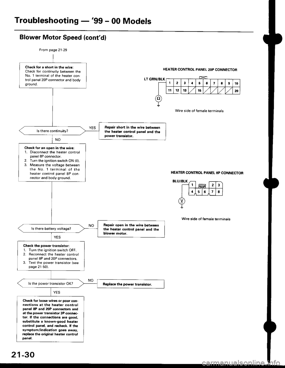
Blower Motor Speed (cont'dl
HEATER CONTROL PANEL 2OP CONNECTOR
Wire side oJ female terminals
Wire side ot female terminals
Frcm page 21.29
LT GRN/BLK
Check tor a short in the wi.a:Check for continuity between theNo. 1 terminal of the heater control panel 20P connector and bodyground.
Repair short in ths wire betwsenthe hoater control panel and theoower transastoa.
Check for an open in the wire:1. Disconnect the heater controlpanel 8P connector,2. Turn the ignjtion switch ON 1ll).3. Measure the voltage betweenthe No. 'l terminal of theheater control panel 8P connector and body ground.
Repeir open in the wiio betweenthe heater control panel and theblower motoa.
Check the power transistor:1. Turn the ignition switch OFF.2. Reconnect the heater controlpanel 8P and 20P connectors.3. Test the power transistor {seepage 21 50).
ls the power transistor OK?
Check for loos€ wiras or poor con-nections at the h€at€r controlpanel 8P and 20P connectols andat th6 power transistor 3P conn€c-tor. lf the connections are good,substituto a known-good hoatercontrol panel, and recheck. It thesymptom/indication goes away,replace the original heater controloanel,
HEATER CONTNOL PANEL 8P CONNECTOR
21-30
Page 1566 of 2189
Starting System
Starter Test lcont'dl
Ch€ck tor Wear and Damage
The starter should crank the engine smoothly and
steadily, lf the starter engages. but cranks the engine
erratically, remove it, and inspect the starter drive gear
and torque converter or flywheel ring gear for damage.
. Check the drive gear overrunning clutch for binding
or slipping when the armature is rotated with the
drive gear held,- lf damaged. replace the gears.
Check Cranking Voltsge and Curr€nt Draw
Cranking voltage should be no less than 8.5 volts.
Current draw should be no more than 350 amperes.
lf cranking voltage is too low, or current draw too high,
check for;
. dead or low batterv.
. open circuit in starter armature commutator seg-
ments,
. starter armature dragging.
. shorted armature winding.
o excessive drag in engine.
Check Cranking rpm
Engine speed during cranking should be above 100 rpm,
lf speed is too low, check for:
. loose battery or stanerterminals.
. excessively worn starter brushes,
. open circuit in commutator segments.
o dirty or damaged helical spline or drive gear.
. defective drive gear overrunning clutch.
Check Siarter Disengag€ment
With the shift lever in El or @ position (A/T) or with the
clutch pedal depressed (M/T), turn the ignition switch to
START (lll), and release to ON (ll).
The starter drive gear should disengage from the torque
converter or flywheel ring gear when you release the
Key.
lf the drive gear hangs up on the torque converter or fly-
wheel ring gear, check for:
. solenoid plunger and switch malfunction,
. dirty drive gear assembly or damaged overrunning
clutch.
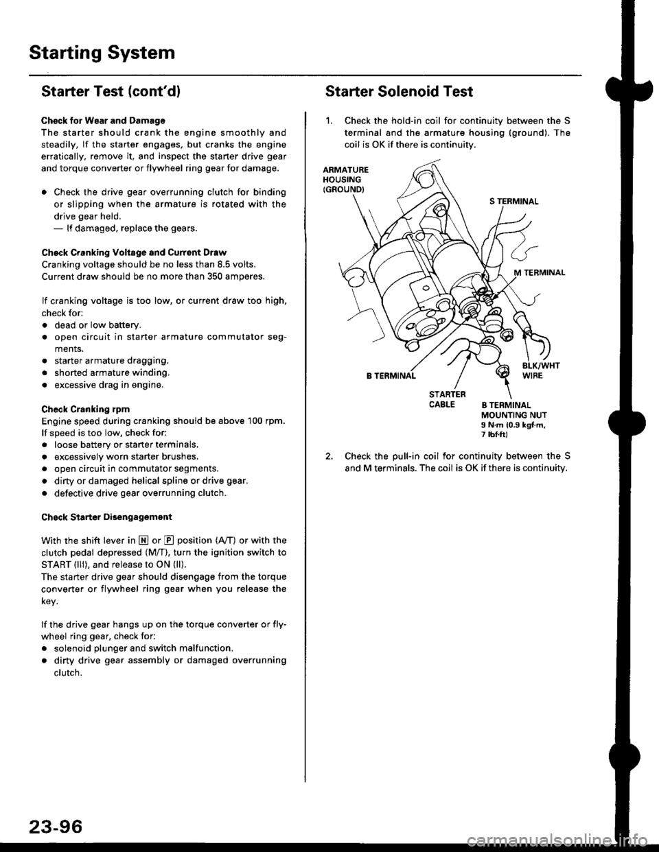
Starter Solenoid Test
1. Check the hold-in coil for continuitv between the S
terminal and the armature housing (ground). The
coil is OK if there is continuitv,
ARMATUREHOUSING(GROUND)
S TERMINAL
M TERMINAL
B TERMINAL
STARTERCAELE B TERMINALMOUNTING NUTI N.m {0.9 kgf.m,7 tbf.ft)
Check the pull-in coil for continuity between the S
and M terminals. The coil is OK if there is continuity.
Page 1586 of 2189
Charging System
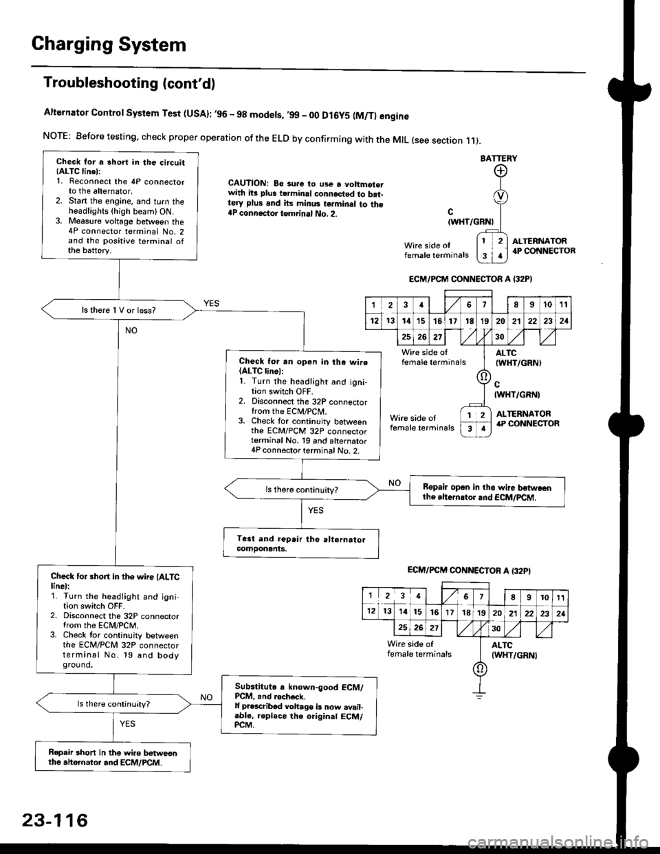
Troubleshooting (cont'd)
Alternator Control System Test (USA): ,96 - 98 modets, ,99 _ 00 Dl6y5 (M/Tl engine
NorE: Before testing. check proper operation of the ELD by confirming with the MrL {see section r 1).
BATTERY
CAUTION: Be 3ure to use a voltmot€.with its plus terminal connected to b.t-tery plus and its minus terminal to the{P connectoi tgmrinal No. 2.c
{WHT/GRNt
Wire side oIfemale terminals
ALTERNATOR.P CONNECTOB
Check for a 3hort in the circuitIALTC linel:1. Reconnect the 4P connectorto the alternator,2. Stan the engine, and turn theheadlights {high beam) ON.3. Measure voltage between the4P connector terminal No. 2and the positive terminal ofthe battery.
ls there 1V or less?
Check for rn opon in tha wire(ALTC linol:1. Turn the headlight and igni-tion switch OFF.2. Disconnect the 32P connectortrom the ECM/PCN4.3. Check tor continuity betweenthe ECM/PCM 32P connectorterminal No. 19 and alternator4P connector terminal No. 2.
Bspair open in thg wire lrstweenthe rhern.tor .nd ECM/PCM.
Check for short in the wire (ALTClinel:1. Turn the headlight and ignition switch OFF.2. Disconnect the 32P connectortrom the ECM/PCM.3. Check tor continuity betweenthe ECM/PCM 32P connectorterminal No. 19 and bodyground.
Subslitute a known-good ECM/PCM, .nd .och6ck.It p.escribod vohago i! now avail-able, replace the original ECM/PCM.
Ropair 3hort in the wiro betweonthe ahe.nator and ECM/PCM.
ECM/PCM CONNECTOR A I32PI
'Ia18I1011
121314151718t9
7
202'l2221
262730
Wire side offemale terminalsALTC(WHT/GRNI
c{WHT/GRNI
ALTERNATORWire side oIfemale terminals
([l
T
12
1
ECM/PCM CONNECTOB A (32PI
I23478910t1
1213 14151617182021222321
262730
Wire side of I AITCfemate terminats
A
(WHT/GRN|
23-116
Page 1587 of 2189
-
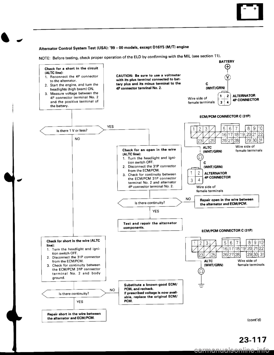
Alternator Control System Test {USA}: '99 - 0O models, except Dl6Y5 {M/T} engine
NOTE: Before testing, check proper operation ofthe ELD by confirming with the MIL (see section 11)'
BATTERY
CAUTION: Be sura lo use a voltmeter
with its plus te.minal conneqted io bat-
tery plus and it3 minus tgrminal to ths
4P connoctot tomrinal No. 2.
Wire side of
female terminals
c(WHT/GRNI
wire side offemale terminals
ALTERNATOR.P CONNECTOR
ECM/PCM CONNECTOR C 13lPI
ECM/PCM CONNECTOR C (31PI
(cont'd)
23-117
Check lor a sho.t in the circuit
{ALTC line):1, Beconnect the 4P connector
to the alternator.
2. Start the engine, and turn the
headlights (high beam) ON.
3. Measure voltage between the
4P connector terminal No. 2
and the Positive terminal of
the battery.
ls there 1 V or less?
Chcck for rn opon in the wire(ALTC lin6l:1. Turn the headlight and igni-
tion switch OFF
2. Disconnect the 31P connector
trom the ECM/PCM.
3. Check for continuity betlveen
the ECM/PCM 31P connectorterminal No. 2 and alternator
4P connector terminal No. 2
Repair opcn in the wire botweon
the alternstoi.nd ECM/PCM.ls there continuity?
Check tor short in the wire IALTC
line):1. Turn the headlight and igni-
tion switch OFF2. Disconnect the 31P connector
from the ECM/PCM.
3. Check for continuity between
the ECM/PCM 31P connector
terminal No. 2 and body
ground.
Substitute a known'good ECM/
PCM, and recheck.It prscribed voltagg is now avail'
abl€, replace tho original ECM/
PCM.
Raoair short in the wite between
the alle.nator and ECM/PCM,
1235618I10
/11611lo191 zo2122
23252621?82930JI
ALTC Wire side of(WHT/GRN) female terminals
o
Page 1733 of 2189
)
l-l
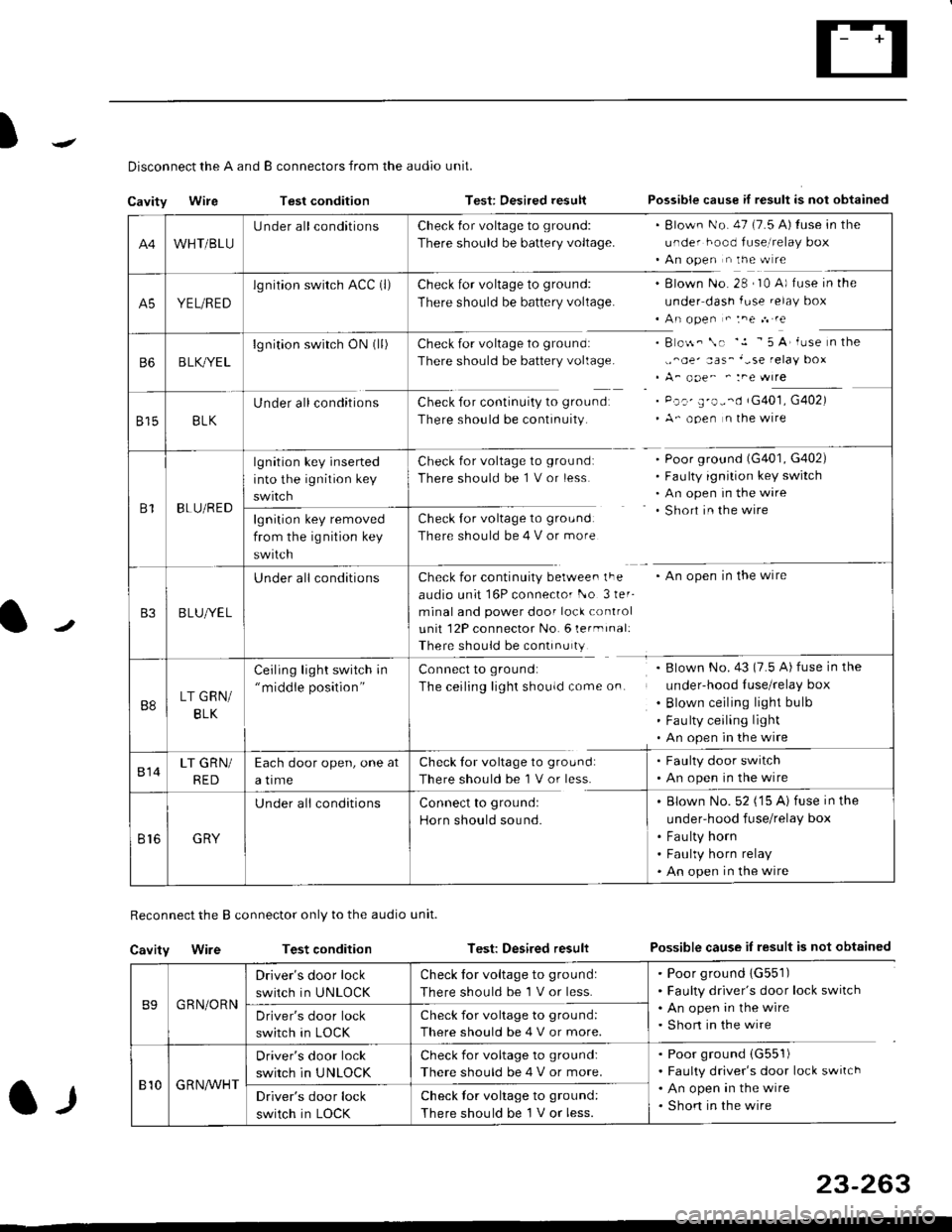
Disconnect the A and B connectors from the audio unit.
Cavity WireTest conditionTest: Desired resultPossible cause if result is not obtained
Reconnect the B connector only to the audio unit.
Cavity WireTest conditionTest: Desired resultPossible cause iI result is not obtained
B9GRN/ORN
Driver's door lock
switch in UNLOCK
Check for voltage to ground:
There should be 1 V or less.
. Poor ground 1G551). Faulty driver's door lock switch. An open in the wire. Short in the wireDriver's door lock
switch in LOCK
Check for voltage to grou nd:
There should be 4 V or more.
810G R NAr'r'HT
Driver's door lock
switch in UNLOCK
Check for voltage to ground:
There should be 4 V or more.
. Poor ground (G551)
. Faulty driver's door lock switch. An open in the wire. Shon in the wireDriver's door lock
switch in LOCK
Check lor voltage to ground:
There should be I V or less.
23-263
A4WHT/BLU
LJnder all conditionsCheck {or voltage to ground:
There should be battery voltage.
. Blown No. 47 (7.5 A) tuse in the
under hood fuse,i relay box. An open n the w re
A5YEL/RED
lg nition swirch ACC (l)Check for voltage to ground:
There should be battery voltage.
Blown No. 28 , I0 A) f use in the
under dash fuse.elay box
An open " :ne n re
Check for voltage to ground:
There should be battery voltage.
Check for continuity to groundr
There should be continuity.
B o$. \. '.1 - 5 A' iuse n the
,,^oe' aas_'-se relay box
A_ ooe^ ' :ne wrre
Pc.' E'o--d rG401, G402)
A- ooen n lhe wire
B6B LK,/YE L
lgnition switch ON0l)
8158LK
Under all conditions
B1BLU/RED
lgnition key inserted
into the ignition key
swrtch
Check for voltage to ground:
There should be 1 V or less
Check for voltage to ground:
There should be 4 V or more
Poor ground (G401, G402)
Faulty ignition key switch
An open in the wire
Short in the wire
An open in the wireCheck for continuity berwee. lFe
audio unit 16P connector l-o 3ler-
minal and power door lock control
unit 12P connector No. 6 lermrnal:
There should be continu ty
lgnition key removed
from the ig nition key
swtlcn
B3B LUlt/E L
U nderall conditions
B8LT GRN/
BLK
Ceiling light switch in"middle position"
Connect to ground:
The ceiling lighr shouldcome on.
Blown No.43 (7.5 A) fuse in the
under-hood Iuse/relay box
Blown ceiling light bulb
Fau lty ceiling light
An open in the wire
814LT GRN/
RED
Each door open, one at
a time
Check tor voltage to ground:
There should be'l V or less.
. Faulty door switch. An open in the wire
Br6GRY
U nderall conditionsConnect to groundl
Horn should sound.
. Blown No. 52 ('15 A) fuse in the
under-hood fuse/relay box
. Fau lty horn. Faulty horn relay. An open in the wire
Page 1748 of 2189
Preca utions/Procedures
Spring-loaded Lock Connector
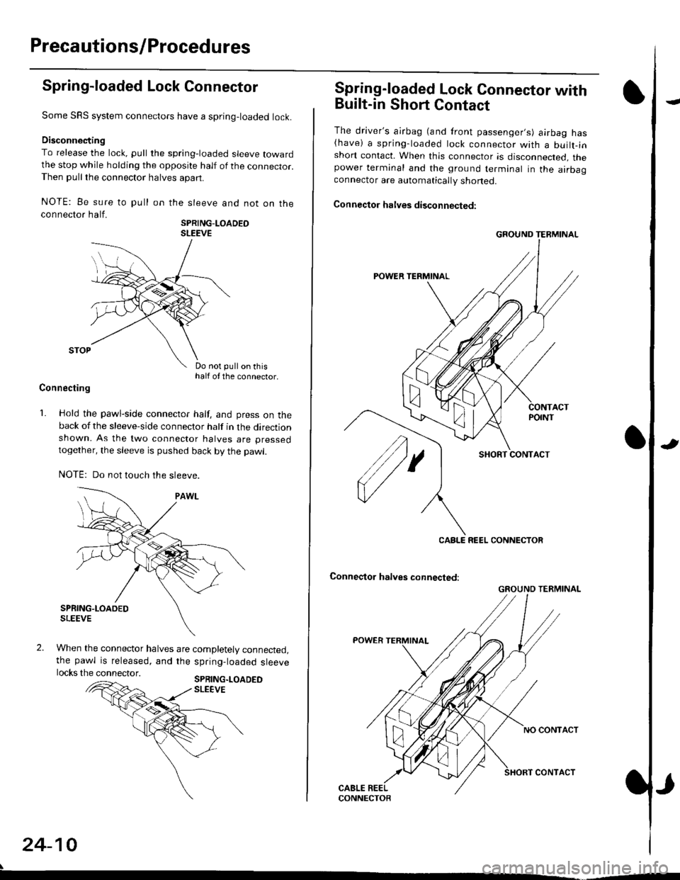
Some SRS system connectors have a spring-loaded lock.
Disconnecting
To release the lock, pull the spring-loaded sleeve towardthe stop while holding the opposite half of the connecror.Then pull the connector halves apart.
NOTE: Be sure to pull
connector half.
on the sleeve and not on the
SPRING-LOADEOSLEEVE
Do not pull on thishalf of the connector.
Connecting
1. Hold the pawl-side connector half, and press on theback of the sleeve-side connector half in the directionshown. As the two connector halves are pressed
together, the sleeve is pushed back by the pawl.
NOTE: Do not touch the sleeve.
When the connector halves are completely connected,the pawl is released, and the spring-loaded sleevelocks the connector.SPRING.LOADEDSLEEVE
24-10
Spring-loaded Lock Connector with
Built-in Short Contact
The driver's ajrbag (and front passenger,s) airbag has(have) a spring-loaded lock connector with a builr-inshort contact. When this connector is disconnected, thepower terminal and the ground terminal in the airbaaconnector are automatically shoned.
Connector halves disconnected:
SHORT CONTACT
Conneqtor halves connected:
GROUND TERMINAL
CABLE REEL CONNECTOR
GROUND TERMINAL
Page 1755 of 2189
l
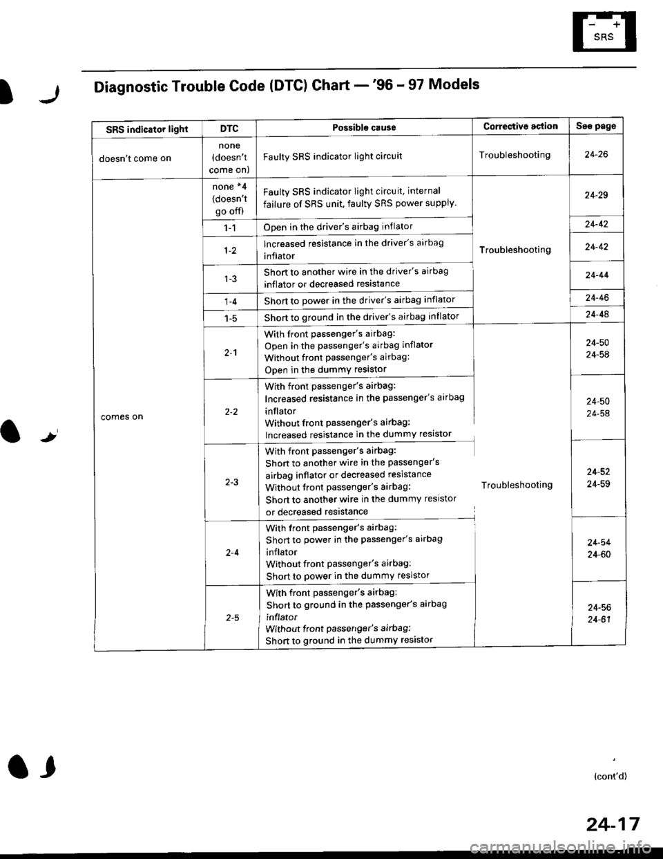
Diagnostic Trouble Code (DTG) Chart -'96 - 97 Models
t
SRS indicator lightDTCPossible causeCorrectiv6 actionSae page
doesn't come on
none(doesn't
come on)
Faulty SRS indicator light circuitTroubleshooting24-26
comes on
none *4
(doesn't
go off)
Faulty SRS indicator light circuit, internal
failure of SRS unit, faulty SRS power supply.
Troubleshooting
24-29
1-1Open in the driver's airbag inflator24-42
lncreased resistance in the driver's aarbag
inflator24-42
l-3Short to another wire in the driver's airbag
inflator or decreased resistance
Short to Dower in the driver's airbag inflator
Short to ground in the driver's airbag inflator
24-44
1-424-46
1-524-48
2-1
With front passenger's airbag:
Open in the passenger's airbag inflator
Without front Passenger's airbag:
ODen in the dummy resistor
24-50
24-54
With front passenger's airbag:
Increased resistance in the passenger's airbag
inflator
Without front Passenger's airbag:
lncreased resistance in the dummy resistor
24,50
24-54
2-3
With front passenger's airbag:
Shon to another wire in the passenger's
airbag inflator or decreased resistance
Without tront passenger's airbag: Troubleshooting
Short to another wire in the dummy resistor
or decreased resistance
24-52
24-59
2-4
With front passenger's airbag:
Short to power in the passenger's airbag
inJlator
Without front Passenger's airbag:
Short to power in the dummy resistor
24-54
24-60
With front passenger's airbag:
Short to ground in the passenger's aarbag
inflator
without front passenger's airbag:
Short to ground in the dummy resistor
24-56
24-61
(cont'd)
24-17
a,