Page 1225 of 2189
Troubleshooting
Main Relay (cont'd)
(From page 19'71)
PCOM(GRN/WHTIscoM(BLK/WHT}Check tor a short to powor in thePCOM, SCOM circuit:1. Turn the ignition switch ON r).2. Measure the voltage betweenbody ground and ABS controlunit 26P connector terminalsNo. l and No.2 individually.
. Repair 3hoit to power in ihercOM circuil wire bgtween theABS control unit end unde.-hood ABS fuse/relay box.. Repair sho to powor in thaPCOM oJ SCOM circuit wirobetwoen the ABS control unitand modulator unit.' Repl.co the modul.tor unit.lshort to Dowcr iGido the unit)Replace the ABS control unit.
Vo lta ge
19-72
Page 1382 of 2189
Troubleshooting -'96 - 98 Models
Blower Motor Speed
HEATER FAN SWITCH 6P CONNECTOR
Wire side of female terminals
21-a
Blower motor runs. but one orrnore speeds are inoperative,
Chsck for a short or an open inthe wire{s}:Turn the ignition switch ON {ll),and the heater fan switch OFF.
Does the blower motor run?
Check for a shon in th6 wirels):1. Turn the ignition switch OFF.2. Disconnect the blower motor2P connector,3. Remove the center dashboardlower cover (see section 20),and disconnect the heater lanswitch 6P connector,4. Disconnect the blower resistor 4P connector,5. Check for continuity betweenthe No. 2,3, 4 and 5lerminalsof the heater fan switch 6Pconnector and body ground
individually.
ls there continuity?Reolace the heater fan switch,
Repair short in the wire(s)beiween the blower resistor, theheater tan switch and the blowermotor,
To page 21 9
Page 1388 of 2189
Troubleshooting -'96 - 98 Models
Mode Control Motor lcont'dl
From page 2l-13HEATER CONTROL PANEL lilP CONNECTOR
Wire side of lemaie terminals
Check tor a short in the wi.e(s):1. Remove the center dashboardlower cover (see section 20),and disconnect the heater con-trol panel 14P connector.2. Check for continuity betweenthe No. 1, 4, 7, 8 and 9 termi-nals and body ground individ-
Raprir.ny short in the wire(s)betw€en the mode control motorand the heater control panel.
Check for a shon to power:
Check the same wires {or voltage.
Repair short to pow6r in thewiro(3) betwoen the mode con-lrol motor .nd tha heate. controlprnel, This short also damag.stho heater cont.ol prnel. Repailthe short to power b€{ore replac-ing the heeter conlrol pan6l.
ls there any voltage?
To page 21 15
21-14
Page 1391 of 2189

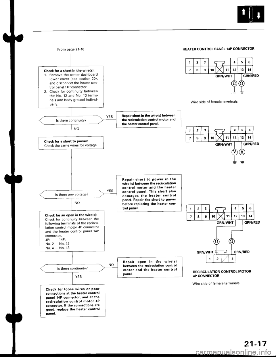
From page 21-16
ls there any voltage?
Check {or a short in the wire(s):1. Remove the center dashboardlower cover (see section 20),
and disconnect the heater con_
trol panel 14P connector'
2. Check for continuity between
the No. 12 and No. 13 termi-
nals and body ground individ-
Repair 5hort in the wire{sl between
the recirculation control motor and
the heater control Panel
Check Ior a short to Power:Check the same wires for voltage
Repair short to Power in the
wire {s) between the recirculationcontrol motor and the heater
control panel. This short also
damages the heater controlpanel. Repair the short to Powerbetore replacing the heater con-
trol panel.
Check lor an open in the wire(s):
Check for continuity between the
following terminals of the recircu
lation control motor 4P connector
and the heater control Panel 14P
4P. 14P:No.2 - No. 12No.4 No. 13
Repair open in the wirelsl
between the recirculation control
motor and the heater controlpanel.
ls there continuitY?
Check for loose wires or Poorconnections at the heater control
Danel 14P connector, and at the
recirculation control motor 4P
connector. lf the connections aregood, replace the heater control
Danel,
HEATER CONTROL PANEL 14P CONNECTOR
I;-?45
789'o lx11121314
GRN/WHT
0) (0
GRN/BED
Wire side of female terminals
GRN/RED
GRN/RED
RECIRCULATION CONTROL MOTOR
4P CONNECTOR
Wire side of female tetminals
I23i--?156
78I'olx11121314
GRN/WHT
V)(v
145
7IIrol\l rr1213
GRN/WHT
r zl/lt
21-17
Page 1395 of 2189

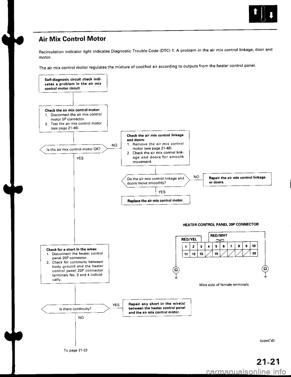
Air Mix Gontrol Motor
Recirculation indicator light indicates Diagnostic Trouble code (DTC) 1l A problem in the air mix control linkage, door and
motor.
The air mix control motor regulates the mixture of cool/hot air according to outputs from the heater control panel'
Self-diagnosis circuit check indi'
cates a Problem in the air mix
conlrol motor circuit,
Check th6 aii mix conirol motor:
1. Disconnect the air mix control
motor 5P connector.
2. Test the air mix control motor(see page 21-46).
check the air mix control linkage
and doors:1. Remove the air mix control
motor (see Page 21-46)
2. Check the air mix control link-
age and doors lor smooth
movement.
ls the air mix control motor OK?
Do the air mix control linkage and
doors move smoolhlY?
R€olace the air mix control motor'
Check tor a short in the wiles:
1. Disconnect the heater controlpanel 20P connector-2. Check for continuitY between
body ground and the heater
control panel 20P connector
terminals No.3 and 4 individ'
uaIY.
Ropair any short in th€ wire{s}
betweon the heater control Paneland the air mix control motor'
HEATER CONTROL PANEL 2OP CONNECTOR
RED/WHTRED/YEL
Wire side ot female terminals
(cont'd)
fo page 21-22
21-21
Page 1397 of 2189

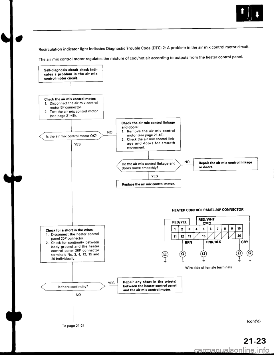
RecirculationindicatorIightindicatesDiagnosticTroublecode(DTc)2:AprobIemintheairmixcontro|motorcircuit.
The air mix control motor regutates the mi)dure of cool/hot air according to outputs from the heater control panel'
Self-diagnosis circuit check indi-
crl6s a problgm in tho air mix
contiol motor circuit.
Check th6 rir mix control motor:
1. Disconnect the air mix control
motor 5P connector'
2. Test the air mix control motor(see page 21-46).
Check the air mix control linkage
and doors:1. Remove the air mix control
motor (see page 21'46).
2. Check the air mix control link-
age and doors for smooth
ls the air mix control motor OK?
Do the air mix control linkage and
doors move smoothlY?
Roglace the air mix conlrol motor.
Check for r short in the wiresl
1. Disconnect the heater controlpanel 20P connector.2. Check for continuity between
body ground and the heater
control panel 20P connector
terminafs No. 3,4. 12,15 a^d
20 individually
Bep.ir any short in the wire{s)
between the h€rter control panel
and th6 air mix control motor.ls there continuity?
HEATER CONTROL PANEL 2OP CONNECTOR
BEO/WHTREO/YEL
PNK/BLK
Wire side of female terminals
(cont'd)
Io page 21-24
21-23
Page 1399 of 2189
![HONDA CIVIC 1998 6.G Workshop Manual Mode control motor does not run.
or one or more modes arc inope]a-
tive.
Check the No. 17 (7.5 A) fuse in
the under-dash fuse/relay box.
Replace the Iuse. and recheck.
Check for an open in the wire:
1 HONDA CIVIC 1998 6.G Workshop Manual Mode control motor does not run.
or one or more modes arc inope]a-
tive.
Check the No. 17 (7.5 A) fuse in
the under-dash fuse/relay box.
Replace the Iuse. and recheck.
Check for an open in the wire:
1](/manual-img/13/6068/w960_6068-1398.png)
Mode control motor does not run.
or one or more modes arc inope]a-
tive.
Check the No. 17 (7.5 A) fuse in
the under-dash fuse/relay box.
Replace the Iuse. and recheck.
Check for an open in the wire:
1. Disconnect the mode control
motor 7P connector,
2. Turn the ignition switch ON (ll)-
3. MeasLrre the voltage between
the No. 1 terminal of themode control motor 7P con
nector and body ground
Repair open in the wire between
the No. 17 luse and lhe mode
control motor.ls there battery voltage?
Check the mode control motor:
1- Turn the ignition switch OFF
2, Test the mode control motor(see page 21 47).Check lhe mode control linkage
and doors:1. Remove the mode controlmotor (see page 21 47).
2. Check the mode control linkage
and doors for smooth move
ls the mode control motor OK?
Do the mode control linkage
and doors move smoothlY?
ReDlace the mode control motor'
Check for a short to Power in the
wires:1. Iurn the,gnitjon switch ON(ll).
2, Disconnect the heater controlpanel20P connector.3. Check for voltage betweenthe No. 2, 5, 6, 7, I and 9 ter'minals of the heater controlpanel 20P connector andbody ground individuallY.Repair shorl to power in the
wire{sl between the heater con-
trol oanel and the mode controlmotor. This short also damagesthe heater control Pan6l. RePair
the short to power before replac'ing the heater control Panel
ls lhere any voltage?
MODE CONTROL MOTOR 7P CONNECTOR
t2315
BLK/YEL
Wire side of female terminals
HEATER CONIROL PANEL 2OP CONNECTOR
Wire side of female terminals
NO
(cont'd)
21-25Io page 21 26
Page 1400 of 2189

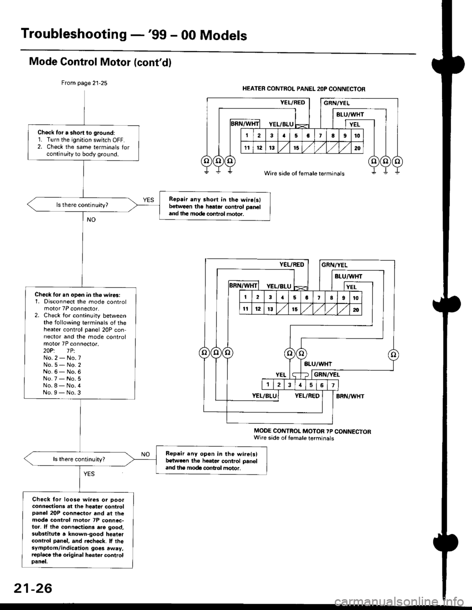
Troubleshooting -'gg - 00 Models
Mode Gontrol Motor (cont'dl
From page 21-25
MODE CONTROL MOTOR ?P CONNECTORWire sade of lemale terminals
Chock tor a short to ground:1. Turn the ignition switch OFF.2. Check the same terminals forcontinuity to body ground.
Repair any 3hort in the wirelslbetween the heater control paneland ihe mode control motor.
ls there continuity?
Check lor.n open in tho wires:1, Disconnect the mode controlmotor 7P connector.2. Check for continuity betweenthe following terminals of theheater control panel 20P connector and the mode controlmotor 7P connector.2OP: lPiNo.2 - No.7No.5- No.2No.6- No.6No.7 - No.5No.8- No.4No.I - No.3
Repair any opon in the wire(s)t€tween the h€ater control paneland tha modc contol motor.
ls there continuity?
Check for loose wiaes or ooorconnections at the heater controlpanel 20P connector rnd at themode control motor 7P connec-toa, lf the connoctions ere good,substitute a known-good heatercontrol panol, and recheck. lf thesyfiptom/indication goes away,replac€ the original hoater controlpanel.
HEATER CONTROL PANEL 2OP CONNECTOR
Wire side of female terminals
21-26