1998 HONDA CIVIC check oil
[x] Cancel search: check oilPage 1134 of 2189
Front Suspension
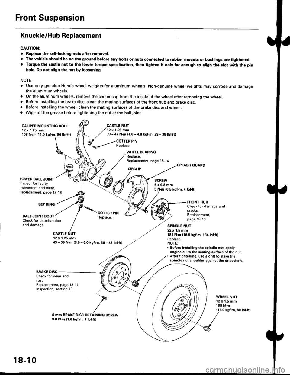
Knuckle/Hub Replacement
CAUTION:
. Replaco tho salf-locking nuts after romoval.
. The vehiclo should be on tho ground bsfore any bohs or nuls connected to rubber mounb or bushings are tightened.. Torqu€ th€ castle nut to the lowor torque specification, ihen tighton it only far enough to align th€ slot whh the pin
hole. Do not align the nut by loosening.
NOTE:
. Use only genuine Honda wheel weights for aluminum wheels. Non-genuine wheel weights may corrode and damagethe aluminum wheels.
. On the aluminum wheels, remove the center cap from the inside of the wheel after removing the wheel,. Before installing the brake disc, clean the mating surfaces of the front hub and brake disc,. Before installing the wheel, clean the mating surfaces of the brake disc and wheel.o Wipe off the grease before tightening the nut at the ball joint.
CALIPER MOUNTING BOLT12 x 1.25 mm108 N.m {11.0 kgl.m, 80lbf.ft)
LOWER BALL JOINTInspect for faultymovement and wear.
CASTLE NUT10 r 1.25 mm39 - ia7 N.m (4.0 - 4.8 kgf.m, 29 - 35 lbf,ftl
COTTER PINReplace.
WHEEL BEARINGReplace.Replacement, page 18-14
CIRCLIP
SCREW5x0.8mm5 N.m {0.5 ksl.m, 4 lbf.ftlReplacement, page 18-16
SET RING
BALL JOINT BOOT
FRONT HUBCheck for damage andcracks.Replacement,page 18-10Check for deteriorationand damage.
CASTLE NUT12 x 1.25 mm49 - 59 N.m l5.O - 6.0 kg{.m. 36 - /(} lbf,ftl
SPINDI.T ]{UT22 r 1.5 mmlEl N.m {18.5 kgf.rn, 13{ lbl.ttlReplace.NOTE:. Before instelling the spindle nut. apply6n9ine oilto th6 seating surface ofthe nut.. Atter tightening, uso a drift to stake thespindle nut should6r against the driveshaft.
BRAKE DISCCheck for wear andrust.Replacement, page 18-11lnspection, section 19.
WHEEL NUT12 x 1.5 mm'108 N.m1r1.0 kgf.m, 8lt lbf.ft)
6 mm BRAKE DISC RETAINING SCREW9.8 N.m 11.0 kgf.m, 7 lbtft)
18-10
Page 1135 of 2189
)
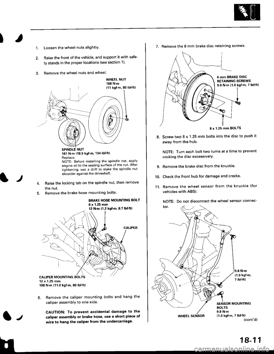
1.Loosen the wheel nuts slightlY.
Raise the front of the vehicle, and support it with safe-
ty stands in the proper locations (see section 1).
Remove the wheel nuts and wheel.3.
l)
WHEEL NUT'108 N.m
18'l N.m 118.5 kgf m, 134lblfti
Replace.NOTEI Before installing the spandle nut, apply
engine oil to the seating surface of the nut After
tightening, use a drift to stake the spindle nut
shoulder againsl the driveshaft
Raise the locking tab on the spindle nut, then remove
the nut.
Remove the brake hose mounting bolts.
BRAKE HOSE MOUNTING BOLT
I x 1.25 mm12 N.m (1,2 kgtm,8,7 lbf'ftl
6. Remove the caliper mounting bolts and hang the
caliper assembiy to one side
CAUTTON: To prevent accidental damage to the
caliper assembly or brake hoso' use a short piece of
wire to hang the caliPer tlom lhe undelcarriage.
{11 kgf m, 80 lbl.ft)
CALIPER MOUNTING BOLTS12 x 1.25 mm108 N.m {'11.0 kgtm, 80 lbt.ft)
7. Remove the 6 mm brake disc retaining screws.
8.
I x 1.25 mm BOLTS
Screw two 8 x 1.25 mm bolts into the disc to push it
away from the hub,
NOTE: Turn each bolt two turns at a tame to prevent
cocking the disc excessivelY.
Remove the brake disc from the knuckle.
Check the front hub for damage and cracks.
Remove the wheel sensor from the knuckle (for
vehicles with ABS).
NOTE: Do not disconnect the wheel sensor connec-
tor.
N.m
6 mm BRAKE OISCRETAINING SCREWS9.8 N.m t1.0 kgf.m, 7 lbf'ft)
{'1.0 kgf m,
7 tbf.ft)
10.
11.
MOUNTING
WHEEL
BOLTS9.8 N.m11.0 kgf,m, 7 lbf'ft)(cont'd)
Page 1142 of 2189
Front Damper
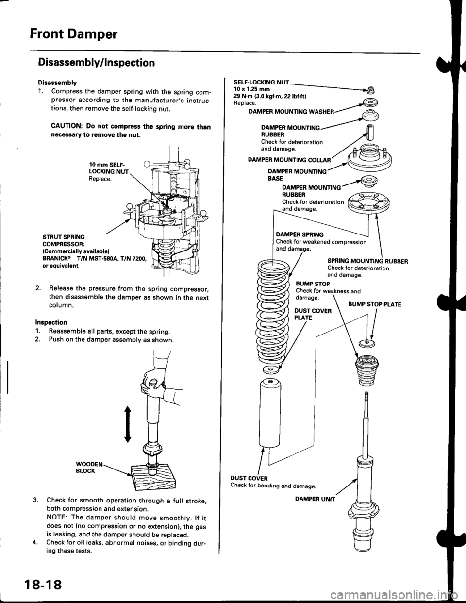
Disassembly/lnspection
Disassembly'1. Compress the damper spring with the spring com-pressor according to the manufacturer,s instruc-
tions, then remove the self-lockino nut.
CAUTION: Do not compress the spring more thann€cessary to remove the nut.
10 mm SELF-LOCKING NUTReplace.
STRUT SPRINGCOMPRESSOR:(Commerci.lly availabl.lBRANICKO T/N MST.s8I}A, T/N 7200,or eouivalent
Release the pressure from thg spring compressor,
then disassemble the damper as shown in the next
column.
Inspostion
1. Reassemble all parts, except the spring.
2. Push on th€ damper assembly as shown.
Check for smooth operation through a full stroke,
both compression and extension,
NOTE: The damper should move smoothlv. lf itdoes not (no compression or no extension), the gas
is leaking, and the damper should be replaced.Check for oil leaks, abnormal noises, or binding dur-ing these tests.
18-18
DAMPER UNIT
Replace.
DAMPER MOUNTING WASHER
BASE
DAMPER MOUNTINGBUBBERCheck for deteriorationand damage.
DAMP€R SPf,INGCheck tor weakened compressionand damage.
SPBING MOUNTING RUBBERCheck for deteriorationand damage,
BUMP STOPCheck fordamage.
DUST COVERPLATE
and
BUMP STOP PLATE
OUST COVERCheck for bending and damage.
Page 1147 of 2189
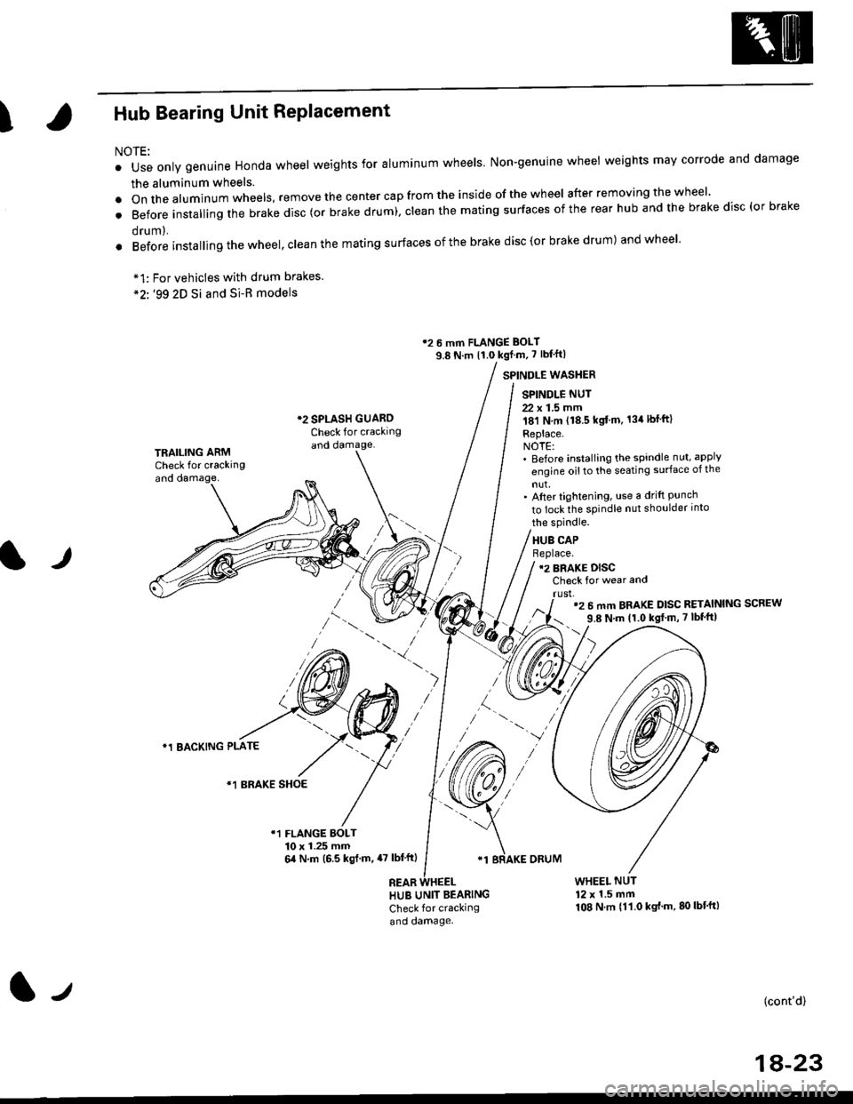
IHub Bearing Unit RePlacement
For vehicles with drum brakes.'99 2D Si and Si-B models
NOTE:
o Use only genuine Honda wheel weights for aluminum wheels Non-genuine wheel weights may corrode and damage
the aluminum wheels.
.onthea|uminumwhee|s,removethecentercapfromtheinsideoftheWhee|afterremovingthewhee|'
. Before insta||ing the brake disc (or brake drum), c|ean the mating surfaces of the rear hub and the brake disc (or brake
orum,.
. Before installing the wheel, clean the mating surfaces ofthe brake disc(or brake drum) andwheel'
*1:
*2'.
12 6 mm FLANGE BOLT
9.8 N.m {1.0 kgf m, 7 lbf'ft|
*2 SPLASH GUAROCheck for crackingand damage.
SPINDLE WASTIER
SPINDLE NUT
22 x 1.5 mm181 N,m (18.5 kgt'm. 134lbfft)
Replace.NOTE:' Before installing the spindle nut, apply
engine oil to the seating surface of the
nut,' After tightening, use a drift Punchto lock the spindle nut shoulder into
TRAILING ARMCheck for crackingand oamage,
lr
the spindle.
HUB CAPBeplace.12 BRAKE DISCCheck for wear and
rust,'2 6 mm BRAKE DISC RETAINING SCREW
9.8 N'm 11.0 kgt m, 7 lbf'ft|
)
*1 BACKING PLATE
/\*1 BRAKE SHOE
r1 FLANGE BOLT10 x 1.25 mm6,0 N.m (6.5 ksl.m,47 lbl'ftl
REAB
'1 BRAKE ORUM
HUB UNIT BEARING
Check for crackingand damage.
WHEEL NUT12 x 1.5 mm108 N.m {11.0 kgt'm.80lbt'ft)
(cont'd)
1A-23
l-t
Page 1148 of 2189
Rear Suspension
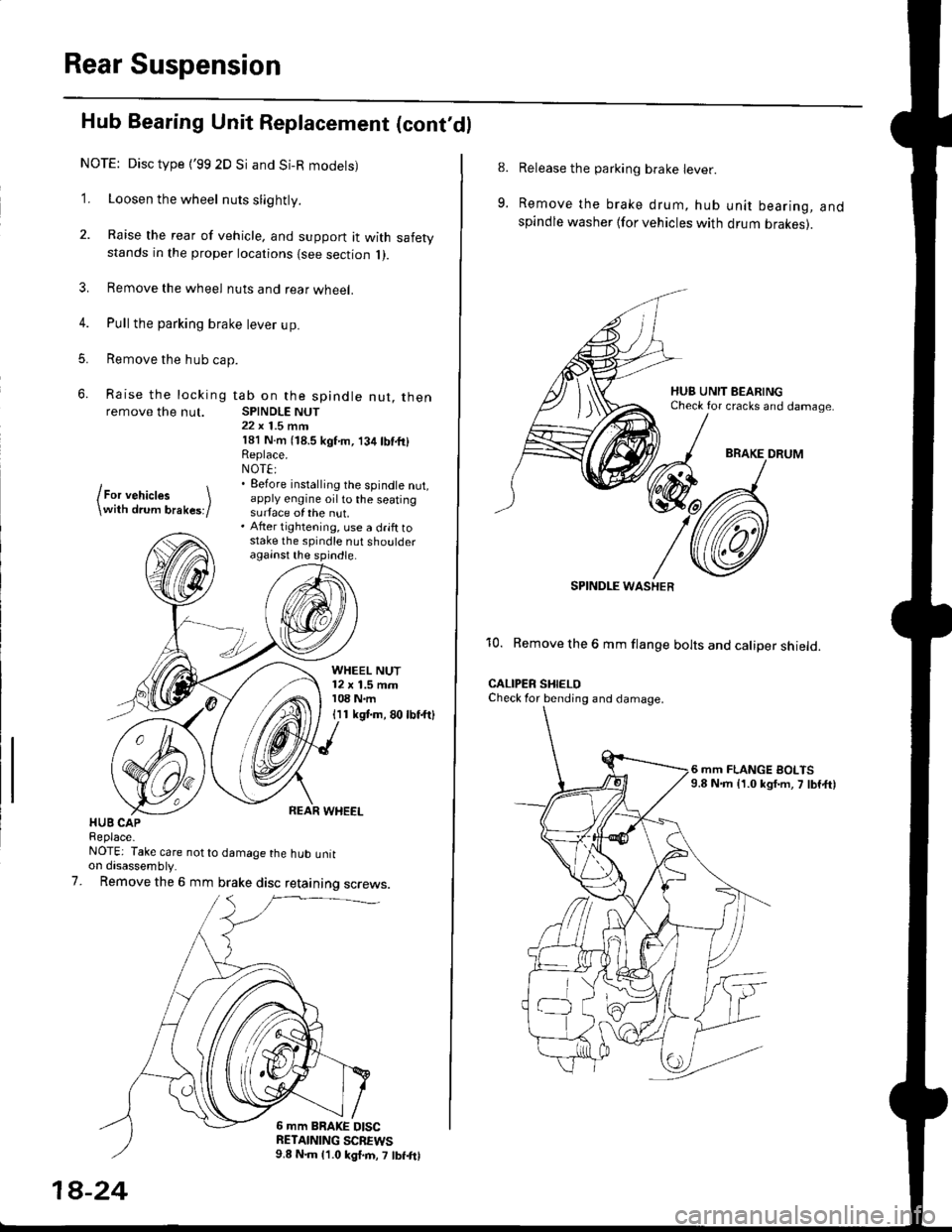
Hub Bearing Unit Replacement (cont'dl
NOTE: Disc type {'99 2D Si and Si-R modets)
1. Loosen the wheel nuts slightly.
2. Raise the rear of vehicle, and support it with safetystands in the proper locations {see section 1).
3. Remove the wheel nuts and rear wheel.
4. Pull the parking brake lever up.
5. Remove the hub cap.
6. Raise the locking tab on the spindle nut, thenremove the nut. SPINDLE NUT22 x 1.5 mrn181 N.m (18.5 kgf'm, 134lbf.fi)Replace.NOT€:. Eefore installing the spindle nut,apply engine oil to the seatingsurface of the nut.. After tightening, use a drift tostake the spindle nut shoulderagainst the spindle.
lFor vehictes \\with drum brakes;/
WHEEL NUT12 x 1.5 mm108 N.m
I I 1 kgt m, 80 lbf.ftl
HUB CAPReplace-NOTE: Take care not to damage the hub untton disassembly.
Remove the 6 mm brake disc retaining screws.7.
6 mm BRAKE DISCRETAINING SCBEWS9.8 N.m 11.0 kgl.m, 7 lbf.frl
1A-24
8.
9.
Release the parking brake lever.
Remove the brake drum, hub unit bearing, andspindle washer lfor vehicles with drum brakes).
BRAKE DRUM
SPINDI-E WASHER
10. Remove the 6 mm flange bolts and caliper shield.
CALIPER SHIELOCheck for bending and damage.
6 mm FLANGE BOLTS9.8 N.m {1.0 kgf.m, 7 lbf,ft)
Page 1151 of 2189
IDisassembly/lnsPection
lr
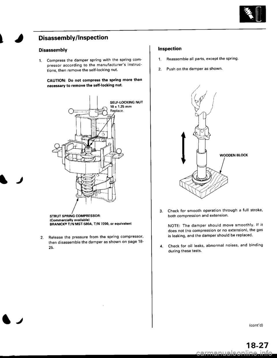
Disassembly
1. Compress the damper spring with the spring com-
pressor according to the manufacturer's instruc-
tions, then remove the self-locking nut.
GAUTION: Do not compress the spring more than
necessary to remove the sell-locking nut.
STNUT SPRING COMPRESSOR:
lComm6rcially .vailablelERANICKo T/N MST-580A, T/N 7200, or equivalent
Release the pressure from the spring compressor.
then disassemble the damper as shown on page 18-
(|-r
lnspection
1. Reassemble all parts, except the sprlng.
2. Push on the damPer as shown.
WOODEN BLOCK
Check for smooth operation through a full stroke,
both compression and extension.
NOTE: The damper should move smoothly lf it
does not (no compression or no extension), the gas
is leaking, and the damper should be replaced.
Check Jor oil leaks, abnormal noises, and binding
during these tests.
{cont'd)
18-27
Page 1175 of 2189
Master Cylinder/Brake Booster
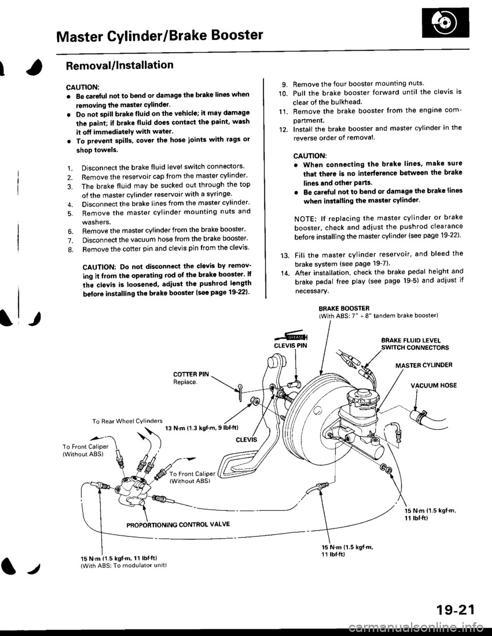
IRemovaUlnstallation
CAUTION:
. Be care{ul nol to bend or damage the brake lines when
rsmoving the mastsr cYlinder.
. Do not soill brakefluid on the vehicle; it may damage
the paint; if brake fluid does contact the paint, wssh
it off immediatelY with water'
. To prevent spill3, cover the hose ioints with rags or
shop towels.
9. Remove the four booster mountlng nuts
10. Pull the brake booster forward until the clevis is
clear of the bulkhead.
11. Remove the brake booster from the engine com-
panmenr.'12. Install the brake booster and master cylinder in the
reverse order of removal.
CAUTION:
. When connecting the brake lines. make sure
that there is no inte erence between the brake
lines and oth6r Parts.
r Be careful not to bend or damage the brake lines
when installing the master cylinder.
NOTE: lf replacing the master cylinder or brake
booster, check and adiust the pushrod clearance
be{ore installing the master cylinder (see page 19-221'
Fill the master cylinder reservoir, and bleed the
brake svstem (see Page 19-7).
After installation. check the brake pedal height and
brake pedal tree play (see page l9-5) and adjust if
necessary.
BRAKE BOOSTER(With ABS: 7" + 8" tandem brake booster)
BRAKE FLUIO LEVELSWITCH CONNECTORS
MASTER CYLINDER
VACUUM HOSE
1.
2.
3,
5.
Disconnect the brake fluid level switch connectors'
Remove the reservoir cap from the master cylinder'
The brake fluid may be sucked out through the top
of the master cylinder reservoir with a syrlnge.
Disconnect the brake lines from the master cylinder'
Remove the master cylinder mounting nuts and
washers.
\l/
6. Remove the master cylinder from the brake booster'
7. Disconnect the vacuum hose trom the brake booster'
8. Remove the cotter pin and clevis pin from the clevis'
CAUTION: Do not disconnect the clevb by remov-
ing it from the operating rod of the brako booster' lf
the clevis is loosened, adiust the pushrod length
before installing th€ brake booster (see page 19-221'
COTTER PINReplace.
To Rear Wheel Cylinders
14.
-6.4CLEVIS PIN
To Front Caliper(Without ABS)$
t'N't'ttrnt'-''
To Front CaliperlWithout ABSi
PBOPORTIONING CONTROL VALVE
15 N.m {1.5 kgl m,11 tbtft)
15 N.m {1.5 kgif.m, 11 lbtft}(With ABS: To modulator unit)lr
19-21
Page 1185 of 2189
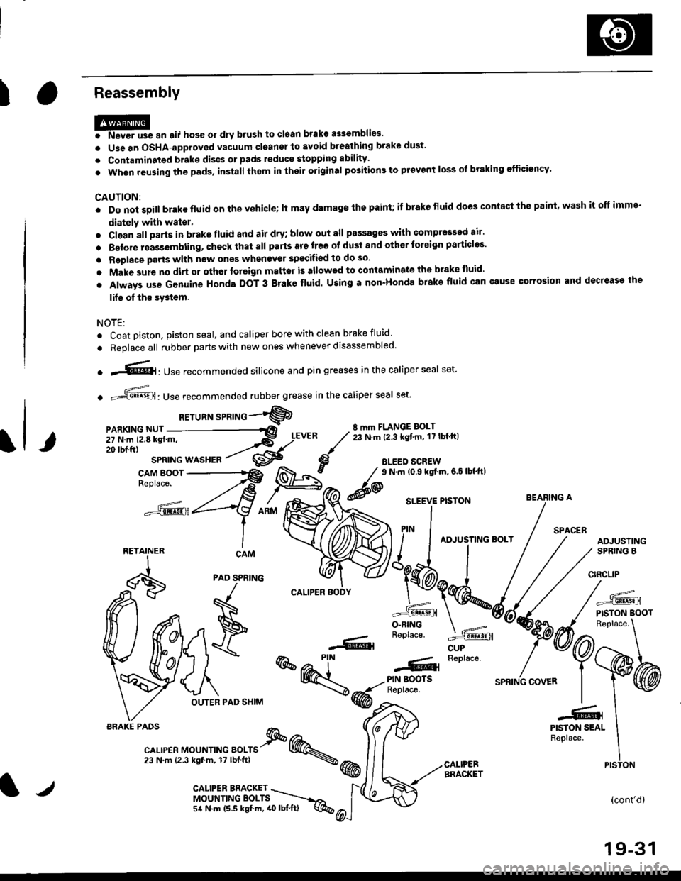
IReassembly
HP* "n ",, hos6 or drv brush to ctoan brake assemblies.
o Use an OSHA-approved vacuum cleanel to avoid brealhing brake dust'
. Contaminated brake discs or pads reduce stopping sbility.
. When reusing the pads, in3tall thom in thoil original positions to prevent loss of braking efficiency'
CAUTION:
. Do not soill brake fluid on the vehicle; lt may damage lhe paint; if brake fluid does contacl the paint' wash it oft imme-
diately with water.
. Cl€an all Darts in brake fluid and air dry; blow out all passagss with comPressed air'
. Belore rsas3embling, check that all parts ars free ot du3t and othor tor€ign particles'
. Replace parts with new ones whenever spscifiod to do so.
o Make sur€ no dirt or othor foreign matter is allowed to contaminate the brake tluid'
. Always use Genuine Honda DOT 3 Brake fluid. Using a non-Honda brake fluid can Gtuse corrosion and decrease the
lif€ of ths system.
NOTE:
. Coat piston, piston seal, and caliper bore with clean brake fluid
. Replace all rubber parts with new ones whenever disassembled.
o .-'{@]: Use recommended silicone and pin greases in the caliper seal set.
. -ffi,Use recommended rubber grease in the caliper seal set.
RETuRN sPRTNG -"'9
8 mm FLANGE BOLT23 N.m (2.3 kgt'm, 17 lbf ftl
BLEED SCREW
@
9 N.m (0.9 kgtm,6.5lbf'ft|
CUP
=^.
PISTON BOOT
(cont'd)
19-31
BEARING A
PAO SPNING
F
\
OUTER PAD SHIM
r--- Replace..ffiPIN BOOTSReplace.
-61
@@-t-.
"l-r,r., "or"'*o " orr" I @.,23 N.m {2.3 kgtm, 17lbf.ftl \@
PISTON SEALReplace.
CALIPEBBRACKET
iiilji:ll;;
__X.,,..".^
BRAKE PAOS
PISTON
l/CALIPER BMCKET \MOUNTINGEOLTS ----.-,o,
54 N.m (5.5 kgf.m, 40lbl.ft) q%