Page 1192 of 2189
Rear Drum Brake
Brake Shoe Reassembly {cont'dl
Connect the parking brake cable to the parking
brake lever.
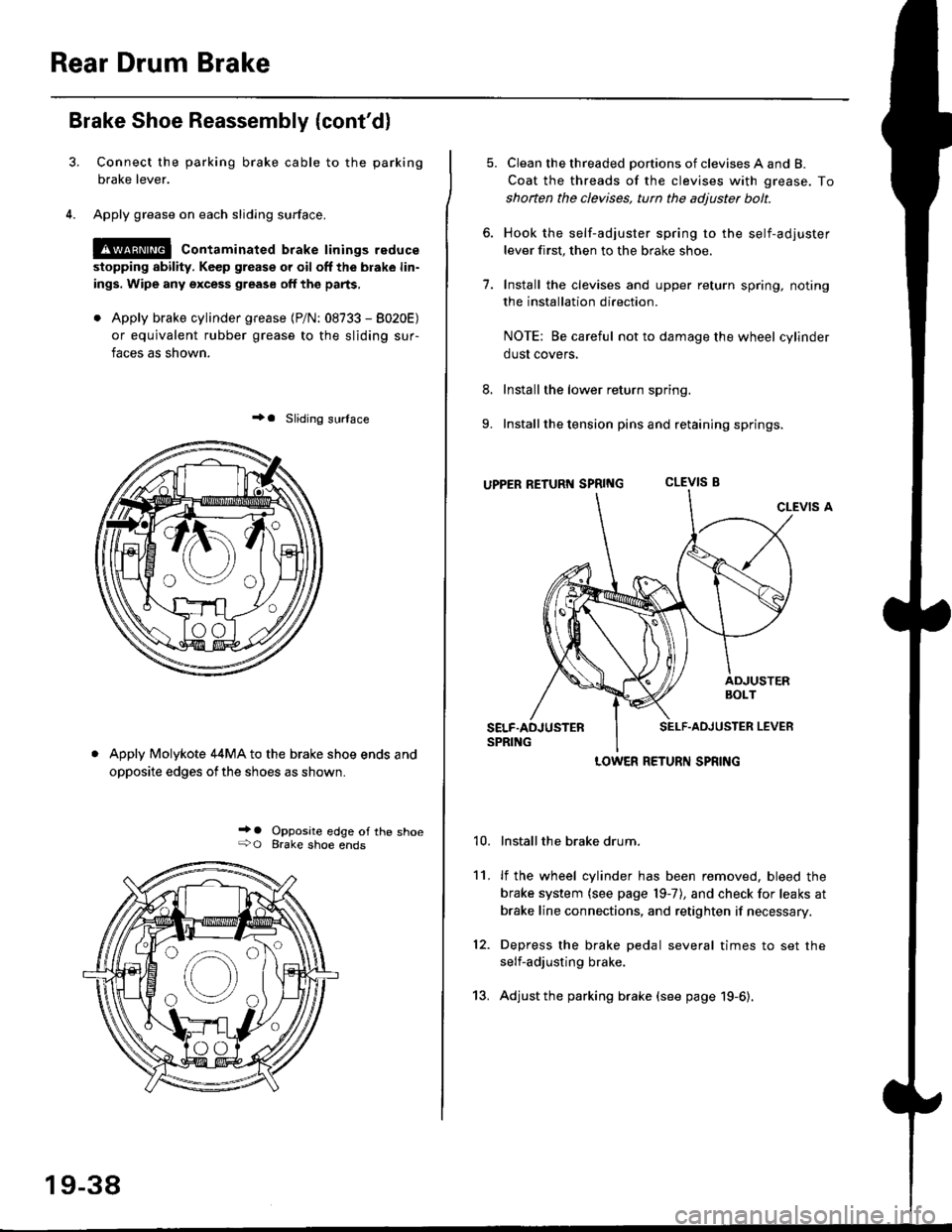
Apply grease on each sliding surface.
!@ contaminated brake linings reduce
stopping ability. Keep grease or oil off the blake lin-
ings. Wipe any excess grease off the parts,
. Apply brake cylinder grease {P/N: 08733 - 8020E)
or equivalent rubber grease to the sliding sur-
faces as shown.
+a Sliding surlace
Apply Molykote 44MA to the brake shoe ends and
opposite edges ofthe shoes as shown.
_' o Opposite edge of the shoe+O Brake shoe ends
19-38
13.
5. Clean the threaded portions of clevises A and B.
Coat the threads of the clevises with grease. To
shoften the clevises, tun the adjuster bolt.
6. Hook the self-adjuster spring to the self-adjuster
lever first, then to the brake shoe
7. Install the clevises and upper return spring. noting
the installation direction.
NOTE: Be careful not to damage the wheel cylinder
dust covers,
8. Install the lower return spring.
9. Install the tension pins and retaining springs.
uppER RETURT{ SpRtNG CLEVIS B
CLEVIS A
Installthe brake drum.
lf the wheel cylinder has been removed, bleed the
brake system (see page 19-7), and check for leaks at
brake line connections, and retighten if necessary.
Depress the brake pedal several times to set the
self-adjusting brake.
Adjust the parking brake (see page 19-6).
't0.
11.
12.
LOWER RETURN SPRING
Page 1266 of 2189
Rear Window
Removal
3D:
CAUTION:
. Put on gloves to ptotect your hands.. Us€ seat cove6 to avoid damaging any surfaces.. Do not damage the rear window defogger grid lines.. Take carg nol scratch the terr window molding.
'1. To remove the rear window, firsr remove the:. Rear center shelf (see page 20-60). Hatch upper trim, hatch trim panel and hatchside trim (see page 20-63)
2.
. Rear window wiper arm (see page 2O-115). Hatch spoiler (see page 20 101)
Disconnect the rear window defogger connectorfrom each side.
Apply protective tape to the inner edge of the tail_gate.
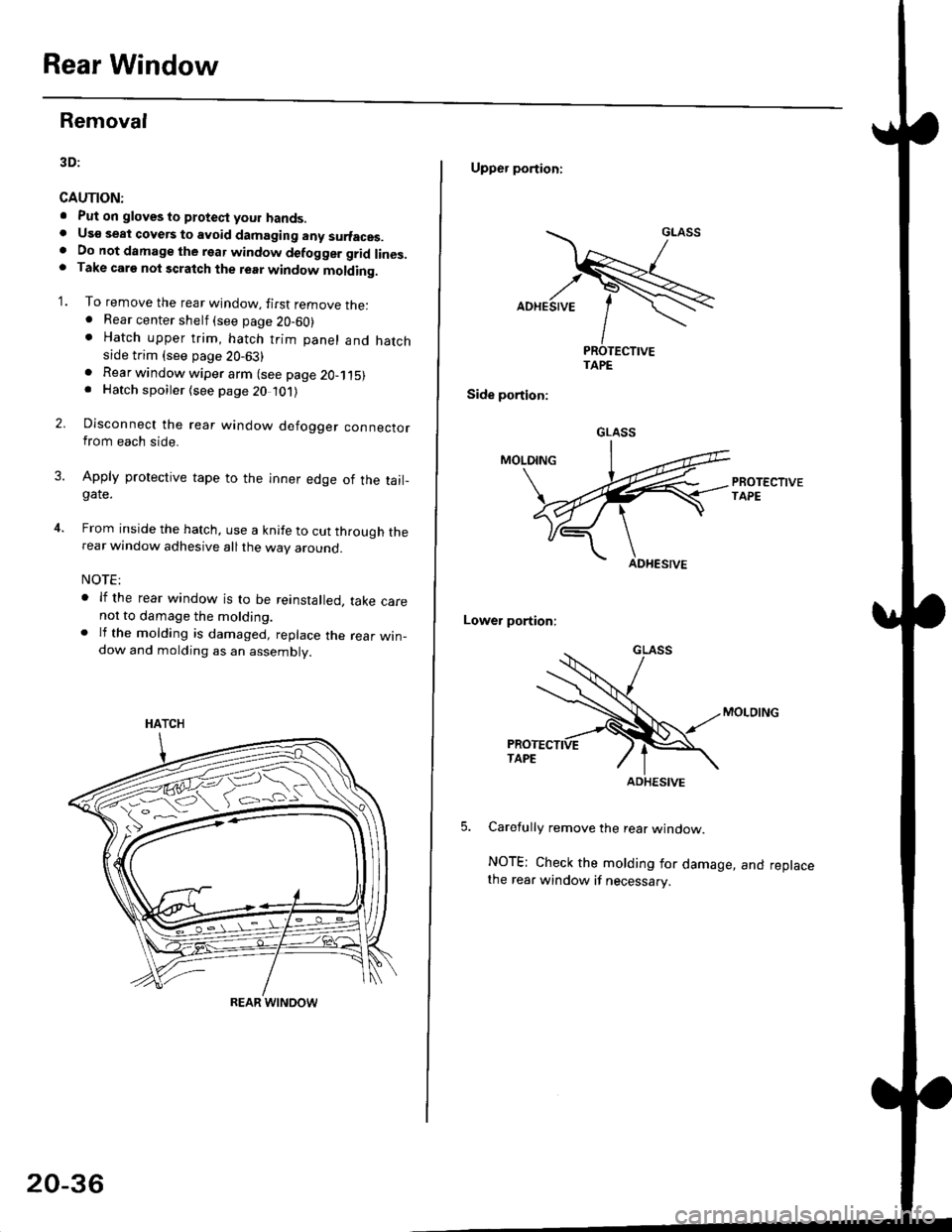
From inside the hatch, use a knife to cut through therear window adhesive all the way around.
NOTE:
. lf the rear window is to be reinstalled, take carenot to damage the molding.. lf the molding is damaged, replace the rear win_dow and molding as an assembly.
HATCH
ffi#
REAR WINOOW
20-36
Upper portioni
TAPE
Side portion:
Lower portion;
Carefully remove the rear window.
NOTE; Check the molding for damage, and replacethe rear window if necessary.
GLASS
ADHESIVE
Page 1271 of 2189
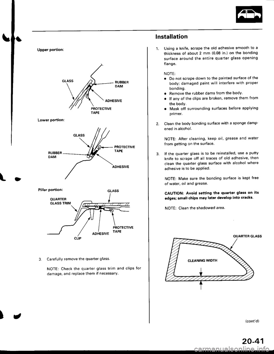
Uppcr portion:
Lower oortion:
PROTECTIVETAPE
l
ADHESIVE
Pillar portion:
Carefully remove the quarter glass
NOTE: Check the quarter glass trim and clips for
damage, and replace them if necessary'
3.
)
AOHESIVE
TAPE
CLIP
lnstallation
1.Using a knife, scrape the old adhesive smooth to a
thickness of about 2 mm (0.08 in.) on the bonding
surtace around the entire quarter glass opening
flange.
NOTE:
. Do not scrape down to the painted surface of the
body; damaged paint will interfere with proper
bonding.
r Remove the rubber dams from the body.
. lf any of the clips are broken, remove them from
the body.
. Mask off surrounding surfaces before applying
pnmer.
Clean the body bonding surface with a sponge damp-
ened in alcohol.
NOTE: Afier cleaning, keep oil, grease and water
from getting on the surface.
lf the quarter glass is to be reinstalled, use a putty
knife to scrape off all traces of old adhesive. then
clean the quaner glass surface with alcohol where
adhesive is to be apPlied.
NOTE: Make sure the bonding surface is kept free
of water, oil and grease.
CAUTION: Avoid setting the quarter glass on its
edges; small chips may later devglop into cracks.
NOTE: Clean rhe shadowed area.
(cont'd)
20-41
Page 1389 of 2189
From page 21-14
Check tor an open in the wire{s}:
Check for continuity between the
following terminals of the mode
control motor 7P connector and
the heater control Panel 14P con-
nector-7P: 14P:No.2 - No.4No.3 - No. 1No.4 - No.7No.5 - No.9No.6- No.8
Repair any opsn in the wirels)
bctwoan the mode control motor
and the hoator conlrol Panolls there continuitY?
Check Io. loo3. wires or Poorconnoctions at lhe hoat€r control
Danel 14P connactor, and 3t the
mod6 conilol motot 7P connec-
tor. It tho connoctions ara good.
rsDlaco the heat€r coilttol panel.
HEATER CONTROL PANEL 14P CONNECTOR
Wire side of {emale terminals
MODE CONTROL MOTOR 7P CONNECTOR
Wire side of female terminals
21-15
Page 1437 of 2189
Ftom page 22 12
Check to. an opon in tho wire:
1. Disconnect the jumper wire
2. Disconnect the comPressor
clutch 1P connector.
3. Check lor continuity between
the No. 1 terminal o{ the com_pressor clutch relaY 4P socket
and the terminal of the com-pressor clutch 1P connector'
Repeir open in the wiro between
the compressoa clutch relaY and
the comDres3or clulch.ls there continuity?
Inspect the comPre3sor clutch
clo.rance, lhe tharmal ProtgdorISANDENI, and tha compr6ssor
clutch field coil {SANDEN: Soepag. 22-33; DENSO: See Pag.22-10t.
COMPRESSOR CLUTCH RELAYiaP SOCKET
r--------t RED
L-r-]-_ll2l I--r- |l1l3l I
@
I
HI
1___J-RED
COMPRESSOR CLUTCH 1P CONNECTOR
Wire side of female terminals
(cont'd)
22-13
Page 1450 of 2189
A/C System Service
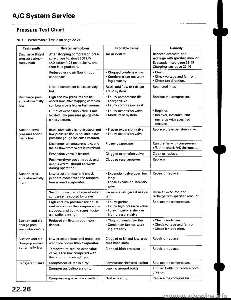
Pressure Test Chart
NOTE: Performance Test is on page 22-24,
Test resultsRelated symptomsProbabl€ causeRemedy
Discharge (high)
pressure aDnor-
mally high
After stopping compressor. pres-
sure drops to about 200 kPa
{2.0 kgflcm,,28 psi) quickly, and
then falls gradually.
Air in systemRecover, evacuate, and
recharge with specified amount.
Evacuation: see page 22-45
Charging: see page 22-46
Reduced or no air flow through
condenser
. Clogged condenser fins. Condenser fan not work-
ing properly
Clean.
Check voltage and fan rpm.
Check fan direction.
Line to condenser is excessively
hot.
Restricted flow of refriger-
ant in system
Restricted lines
Discharge pres-
sure abnormally
High and low pressures are bal-
anced soon after stopping compres-
sor, Low side is higher than normal.
. Faulty compressor dis-
charge valve. Faulty compressor seal
Replace the compressor.
Outlet of expansion valve is not
frosted, low pressure gauge indi-
cales vacuum.
. Faulty expansion valve. Moisture in system
. Replace,. Recover, evacuate, and
recharge with specified
amount.
Suction (low)
pressure abnor-
mally low
Expansion valve is not frosted, and
low oressure line is not cold. Low
pressure gauge indicates vacuum.
. Frozen expansion valve. Faulty expansion valve
ReDlace the exoansion valve.
Discharge temperature is low. and
the air flow from vents is restricted.
Frozen evaporatorRun the fan with compressor
off. then check A,/C thermostat.
Exoansion valve is frosted.Clogged expansion valveClean or replace.
Receiver/dryer outlet is cool, and
inlet is warm (should be warm
during operation).
Clogged receiver/dryerReplace.
Suction pres-
sure abnormally
hig h
Low pressure hose and check
joint are cooler than the tempera-
ture around evaporator.
. Expansion valve open too
long. Loose expansion capillary
tube
Repair or replace.
Suction oressure is lowered when
condenser is cooled bv water.
Excessive refrigerant in sys-
tem
Recover. evacuate, and
recharge with specified amount.
High and low pressure are equal-
ized as soon as the compressor is
stopped, and both gauges fluctu-
ate while running.
Faulty gasket
Faulty high pressure valve
Foreign particle stuck in
high pressure valve
Replace the compressor.
Suction and dis-
charge pres-
sures abnormally
h igh
Reduced air flow through con-
denser.
. Clogged condenser fins. Condenser fan not work-
ing properly
Clean condenser.
Check voltage and fan rpm.
Check fan direction.
Suction and dis-
charge pressure
abnormally low
Low pressure hose and metal end
areas are cooler than evaporator.
Clogged or kinked low pres-
sure hose parts
Repair or replace.
Temperature around expansion
valve is too low compared with
that around receiver/dryer.
Clogged high pressure lineRepair or replace.
Refrigerant leaksCompressor clutch is diny,Compressor shaft seal leakingReplace the compressor.
Compressor bolt{s) are diny.Leaking around bolt(s)Tighten bolt(s) or replace com-
pressor.
Compressor gasket is wet with oil.Gasket leakingReplace the compressor.
22-26
Page 1457 of 2189
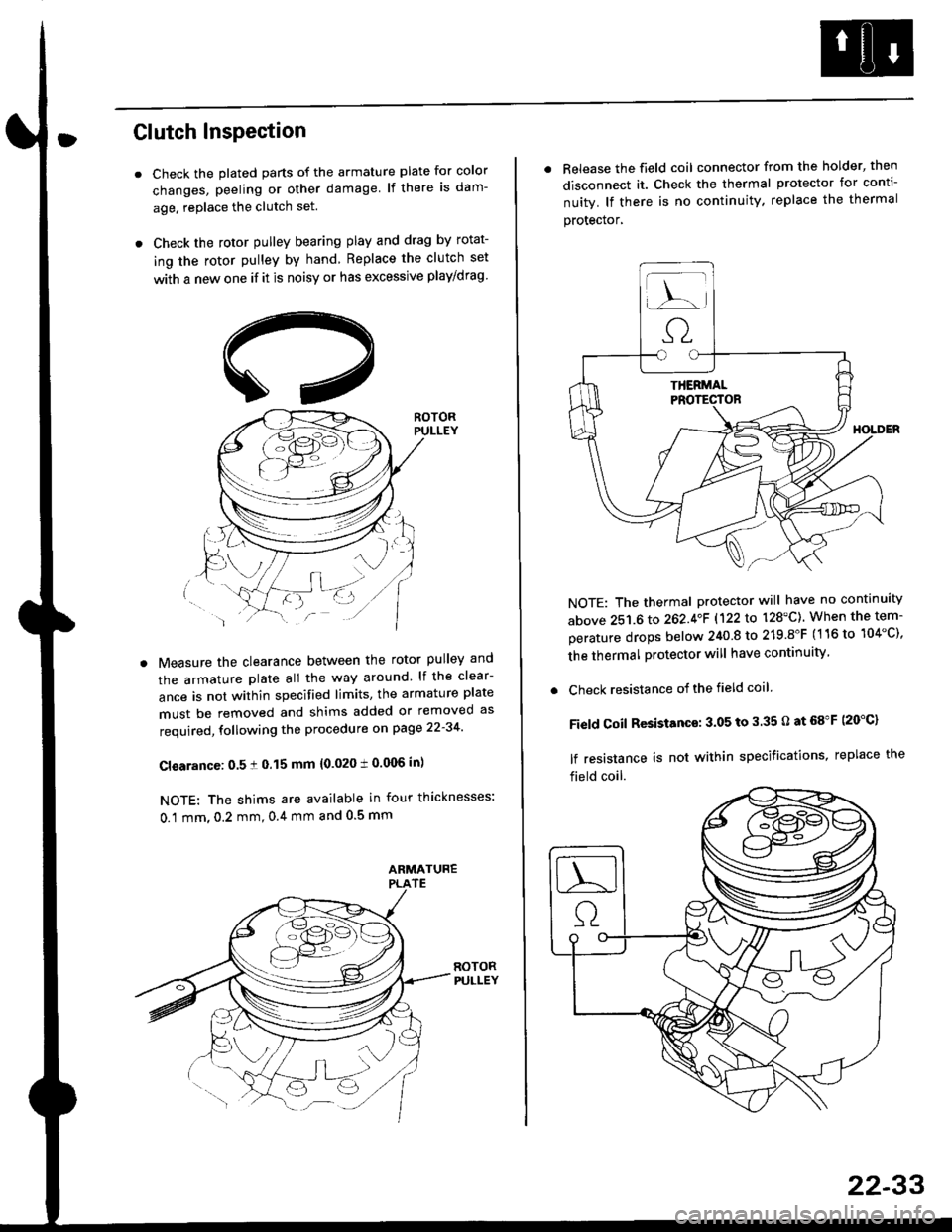
Clutch InsPection
Check the plated parts of the armature plate for color
changes, peeling or other damage lf there is dam-
age. replace the clutch set.
Check the rotor pulley bearing play and drag by rotat-
ing the rotor pulley by hand Replace the clutch set
with a new one if it is noisy or has excessive play/drag
Measure the clearance between the rotor pulley and
the armature plate all the way around lf the clear-
ance is not within specified limits, the armature plate
must be removed and shims added or removed as
required, following the procedure on page 22-34
Cl€arance: 0.5 ! 0.15 mm {0.020 t 0.006 in)
NOTE: The shims are available in four thicknesses:
0.1 mm,0.2 mm,0.4 mm and 0.5 mm
. Release the field coil connector from the holder' then
disconnect it. Check the thermal protector for conti-
nuity. lf there is no continuity. replace the thermal
protecror,
NOTE: The thermal protector will have no continuity
above 251.6 to 262.4oF 1122lo 128'C). When the tem-
perature drops below 240 8 to 219.8"F (116 to 104"C),
the thermal protector will have continuity
. Check resistance of the field coil
Field Coil Resistance: 3.05 to 3.35 O at 68"F (20"C)
lf resistance is not within specifications, replace the
field coil.
22-33
Page 1459 of 2189
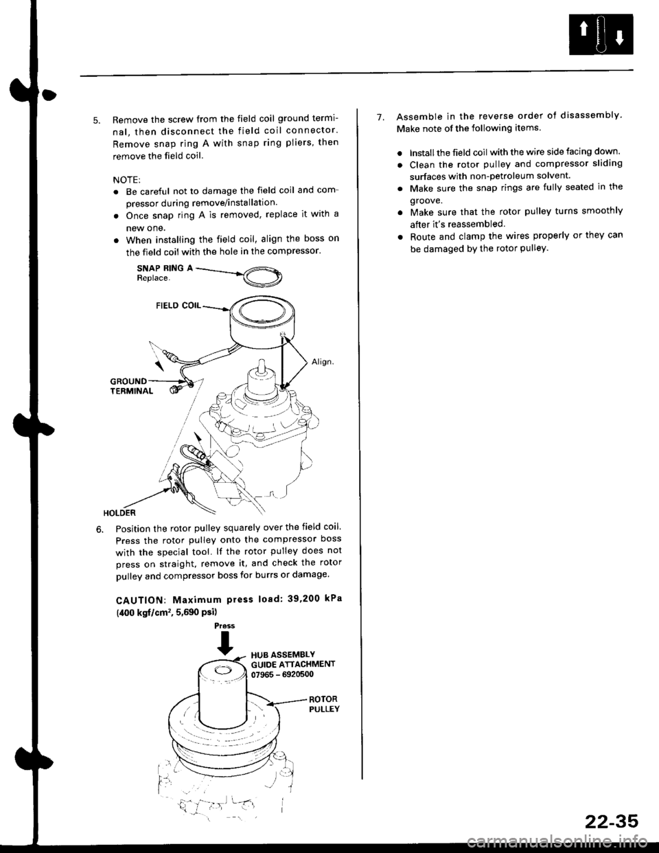
5. Remove the screw from the field coil ground termi-
nal, then disconnect the field coil connector.
Remove snap ring A with snap ring pliers, then
remove the field coil
NOTE:
. Be careful not to damage the field coil and com-
pressor during remove/installation.
. Once snap ring A is removed, replace it with a
new one.
. When installing the field coil, align the boss on
the field coil with the hole in the compressor.
SNAP RING AReplace.
Position the rotor pulley squarely over the field coil.
Press the rotor pulley onto the compressor boss
with the special tool. lf the rotor pulley does not
press on straight, remove it, and check the rotor
pulley and compressor boss for burrs or damage.
CAUTION: Maximum press load: 39,200 kPa
(,[00 kgf/cm'�, 5,590 Psi)
Press
THUB ASSEMBLYGUIDE ATTACHMENT07965 - 6920500
ROTORPULLEY
t'l
i,'
7. Assemble in the reverse order of disassembly
Make note of the following items.
. lnstall the field coil with the wire side facing down.
. Clean the rotor pulley and compressor sliding
surfaces with non-petroleum solvent.
. Make sure the snap rings are fully seated in the
groove.
. Make sure that the rotor pulley turns smoothly
after it's reassembled
. Route and clamp the wires properly or they can
be damaged bY the rotor Pulley.
22-35