Page 82 of 216
If the air bag is inflated,
the air bag will not
function again and must be
replaced immediately.Ifthe
air bag is not replaced, the
unrepaired area will increase the
risk of injury in a collision.
The SRS consists of:
²driver and passenger air bag
modules (which include the
inflators and air bags),
²one or more impact and safing
sensors,
²a readiness light and tone
²and the electrical wiring which
connects the components.
The diagnostic module monitors its
own internal circuits and the
supplemental air bag electrical
system warning (including the
impact sensors), the system wiring,
the air bag system readiness light,
the air bag back up power and the
air bag ignitors.
Determining if the system is
operational
The SRS uses a readiness light in
the instrument cluster or a tone to
indicate the condition of the
system. Refer to theAir bag
readinesssection in the
Instrumentationchapter. Routine
maintenance of the air bag is not
required.
Seating and safety restraints
82
Page 119 of 216

If your vehicle is equipped with
the optional heavy duty trailer tow
wiring, it is pre-wired for trailer
towing. An electrical connector is
provided under the instrument
panel for installing a
customer-supplied electric brake
controller. Another electrical
connector is provided at the hitch.
This connector provides power to
the trailer for taillamps, stop and
turn lamps, back up lamps, battery
charge, electric brakes (when a
customer provided controller is
installed) and ground. The kit
included with your vehicle
provides you with adaptors to
attach the brake controller and
convert the hitch connector for
Class I trailer usage.
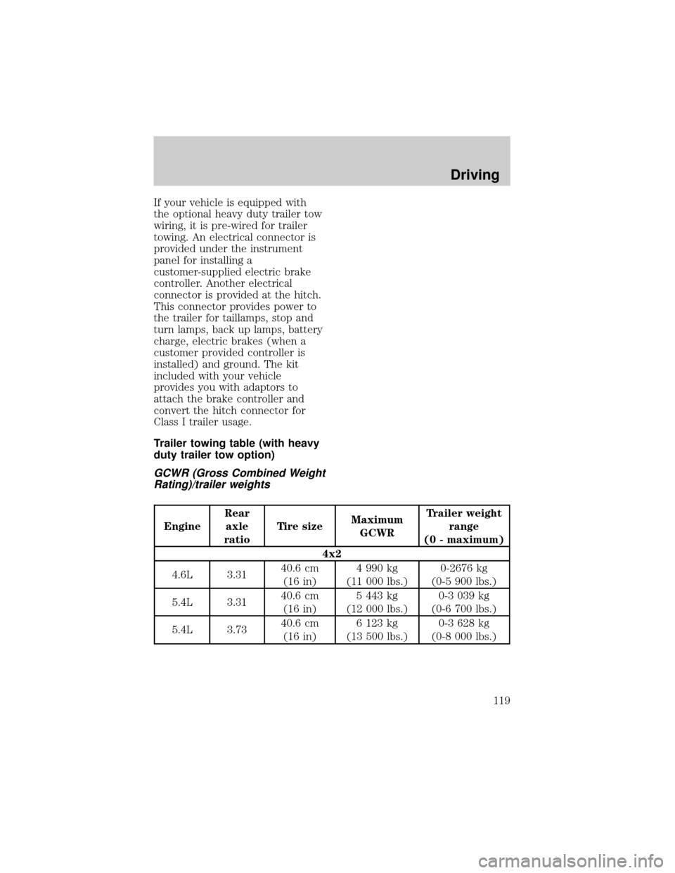
Trailer towing table (with heavy
duty trailer tow option)
GCWR (Gross Combined Weight
Rating)/trailer weights
EngineRear
axle
ratioTire sizeMaximum
GCWRTrailer weight
range
(0 - maximum)
4x2
4.6L 3.3140.6 cm
(16 in)4 990 kg
(11 000 lbs.)0-2676 kg
(0-5 900 lbs.)
5.4L 3.3140.6 cm
(16 in)5 443 kg
(12 000 lbs.)0-3 039 kg
(0-6 700 lbs.)
5.4L 3.7340.6 cm
(16 in)6 123 kg
(13 500 lbs.)0-3 628 kg
(0-8 000 lbs.)
Driving
119
Page 177 of 216

or equivalent. SAE class ªSº or
other conventional link type
chains may contact and cause
damage to the vehicle's wheel
house and/or body.
²Install chains securely, verifying
that the chains do not touch any
wiring, brake lines or fuel lines.
²Drive cautiously. If you hear the
chains rub or bang against your
vehicle, stop and re-tighten the
chains. If this does not work,
remove the chains to prevent
damage to your vehicle.
²If possible, avoid fully loading
your vehicle.
²Remove the tire chains when
they are no longer needed. Do
not use tire chains on dry roads.
²The suspension insulation and
bumpers will help prevent
vehicle damage. Do not remove
these components from your
vehicle when using snow tires
and chains.
²Do not exceed 48 km/h (30
mph) with tire chains on your
vehicle.
WHAT YOU SHOULD KNOW
ABOUT AUTOMOTIVE FUELS
Important safety precautions
Do not overfill the fuel
tank. The pressure in an
overfilled tank may cause
leakage and lead to fuel spray
and fire.
Maintenance and care
177
Page 187 of 216
Replacing headlamp bulbs
Handle a halogen
headlamp bulb carefully
and keep out of children's reach.
Grasp the bulb only by its plastic
base and do not touch the glass.
The oil from your hand could
cause the bulb to break the next
time the headlamps are
operated.
1. Make sure that the headlamp
control is in the OFF position.
2. Open the hood.
3. At the back of the headlamp,
pull clips rearward and up (about
ôº) to release the headlamp
assembly.
4. Slide headlamp assembly
forward and off of guide ribs to
expose the back of the bulb and
wiring connector.
5. Remove the electrical connector
from the bulb by grasping the wire
and pulling it rearward.
6. Remove bulb retainer ring by
turning it counterclockwise about
1¤4turn, then slide the ring off the
plastic base.
7. Without turning, carefully pull
bulb assembly out of headlamp
assembly.
Maintenance and care
187