1998 DODGE RAM 1500 oil level
[x] Cancel search: oil levelPage 1446 of 2627
minutes before checking oil level. Checking engine oil
level on a cold engine is not accurate.
To ensure proper lubrication of an engine, the
engine oil must be maintained at an acceptable level.
The acceptable levels are indicated between the ADD
and SAFE marks on the engine oil dipstick.
(1) Position vehicle on level surface.
(2) With engine OFF, allow approximately five
minutes for oil to settle to bottom of crankcase,
remove engine oil dipstick.
(3) Wipe dipstick clean.
(4) Install dipstick and verify it is seated in the
tube.
(5) Remove dipstick, with handle held above the
tip, take oil level reading.
(6) Add oil only if level is below the ADD mark on
dipstick.
ENGINE OIL CHANGE
Change engine oil at mileage and time intervals
described in Maintenance Schedules(Refer to LUBRI-
CATION & MAINTENANCE/MAINTENANCE
SCHEDULES - DESCRIPTION).
Run engine until achieving normal operating tem-
perature.
(1) Position the vehicle on a level surface and turn
engine off.
(2) Hoist and support vehicle on safety stands.
(3) Remove oil fill cap.
(4) Place a suitable drain pan under crankcase
drain.
(5) Remove drain plug from crankcase and allow
oil to drain into pan. Inspect drain plug threads for
stretching or other damage. Replace drain plug if
damaged.
(6) Install drain plug in crankcase. Torque to 34
N´m ( 25 ft. lbs.).
(7) Lower vehicle and fill crankcase with specified
type and amount of engine oil described in this sec-
tion.
(8) Install oil fill cap.
(9) Start engine and inspect for leaks.
(10) Stop engine and inspect oil level.
USED ENGINE OIL DISPOSAL
Care should be exercised when disposing used
engine oil after it has been drained from a vehicle
engine. Refer to the WARNING at beginning of this
section.
OIL FILTER
REMOVAL
All engines are equipped with a high quality full-
flow, disposable type oil filter. DaimlerChrysler Cor-
poration recommends a Mopartor equivalent oil
filter be used.
(1) Position a drain pan under the oil filter.
(2) Using a suitable oil filter wrench loosen filter.
(3) Rotate the oil filter counterclockwise to remove
it from the cylinder block oil filter boss.
(4) When filter separates from cylinder block oil
filter boss, tip gasket end upward to minimize oil
spill. Remove filter from vehicle.
NOTE: Make sure filter gasket was removed with fil-
ter.
(5) With a wiping cloth, clean the gasket sealing
surface of oil and grime.
INSTALLATION
(1) Lightly lubricate oil filter gasket with engine
oil.
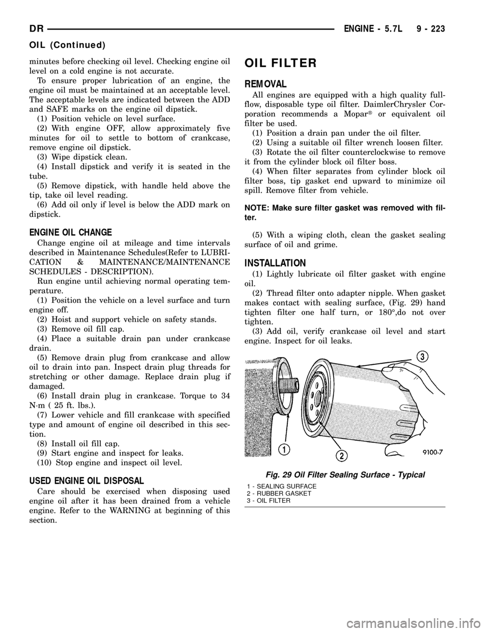
(2) Thread filter onto adapter nipple. When gasket
makes contact with sealing surface, (Fig. 29) hand
tighten filter one half turn, or 180É,do not over
tighten.
(3) Add oil, verify crankcase oil level and start
engine. Inspect for oil leaks.
Fig. 29 Oil Filter Sealing Surface - Typical
1 - SEALING SURFACE
2 - RUBBER GASKET
3 - OIL FILTER
DRENGINE - 5.7L 9 - 223
OIL (Continued)
Page 1454 of 2627
CRANKSHAFT OIL SEAL - FRONT
REMOVAL............................275
INSTALLATION........................275
CRANKSHAFT OIL SEAL - REAR
REMOVAL............................276
INSTALLATION........................276
CRANKSHAFT REAR OIL SEAL RETAINER
REMOVAL............................277
INSTALLATION........................277
SOLID LIFTERS/TAPPETS
REMOVAL............................279
CLEANING...........................279
INSPECTION.........................279
INSTALLATION........................280
PISTON & CONNECTING ROD
DESCRIPTION........................281
STANDARD PROCEDURE - HEAD GASKET
SELECTION.........................281
REMOVAL............................281
CLEANINGÐPISTON AND CONNECTING
ROD ..............................282
INSPECTION
INSPECTION - PISTONS...............282
INSPECTIONÐCONNECTING ROD.......283
INSTALLATION........................283
PISTON RINGS
STANDARD PROCEDURE - PISTON RING
FITTING............................284
VIBRATION DAMPER
REMOVAL............................285
INSPECTION.........................285
INSTALLATION........................286
FRONT MOUNT
REMOVAL............................286
INSTALLATION........................287
REAR MOUNT
REMOVAL............................288
INSTALLATION........................288
LUBRICATION
DESCRIPTION........................289
OPERATION..........................289
DIAGNOSIS AND TESTINGÐENGINE OIL
PRESSURE.........................289
OIL
STANDARD PROCEDURE
STANDARD PROCEDURE - ENGINE OIL
LEVEL.............................292STANDARD PROCEDURE - ENGINE OIL
SERVICE...........................292
OIL COOLER & LINES
CLEANING
CLEANING AND INSPECTION...........293
OIL FILTER
REMOVAL............................293
INSTALLATION........................293
OIL PAN
REMOVAL............................293
CLEANING...........................293
INSPECTION.........................293
INSTALLATION........................293
OIL PRESSURE RELIEF VALVE
REMOVAL............................294
CLEANING...........................294
INSPECTION.........................294
INSTALLATION........................294
OIL PRESSURE SWITCH
REMOVAL............................294
INSTALLATION........................294
OIL PUMP
REMOVAL............................294
CLEANING...........................295
INSPECTION.........................295
INSTALLATION........................296
INTAKE MANIFOLD
REMOVAL............................297
CLEANING...........................297
INSPECTION.........................297
INSTALLATION........................298
EXHAUST MANIFOLD
REMOVAL............................298
CLEANING...........................298
INSPECTION.........................298
INSTALLATION........................298
VALVE TIMING
STANDARD PROCEDURE - TIMING
VERIFICATION.......................299
GEAR HOUSING
REMOVAL............................299
INSTALLATION........................300
GEAR HOUSING COVER
REMOVAL............................301
INSTALLATION........................301
DRENGINE 5.9L DIESEL 9 - 231
Page 1456 of 2627
DIAGNOSIS AND TESTING
DIAGNOSIS AND TESTINGÐENGINE DIAGNOSIS - MECHANICAL
CONDITION POSSIBLE CAUSES CORRECTION
LUBRICATING OIL
PRESSURE LOW1. Low oil level. 1. (a) Check and fill with clean engine oil.
(b) Check for a severe external oil leak that
could reduce the pressure.
2. Oil viscosity thin, diluted or wrong
specification.2. (a) Verify the correct engine oil is being
used. (Refer to LUBRICATION &
MAINTENANCE/FLUID TYPES -
DESCRIPTION).
2. (b) Look for reduced viscosity from fuel
dilution.
3. Improperly operating pressure
switch/gauge.3. Verify the pressure switch is functioning
correctly. If not, replace switch/gauge.
4. Relief valve stuck open. 4. Check/replace valve.
6. If cooler was replaced, shipping
plugs may have been left in cooler6. Check/remove shipping plugs.
7. Worn oil pump. 7. Check and replace oil pump.
8. Suction tube loose or seal leaking. 8. Check and replace seal.
9. Loose main bearing cap. 9. Check and install new bearing. Tighten
cap to proper torque.
10. Worn bearings or wrong bearings
installed.10. Inspect and replace connecting rod or
main bearings. Check and replace directed
piston cooling nozzles.
11. Directed piston cooling nozzles
under piston, bad fit into main
carrier.11. Check directed piston cooling nozzles
position.
12. Loose oil rifle plug with saddle-jet
style nozzles12.Tighten oil rifle plug.
13. Loose directed piston cooling
nozzle.13. Tighten directed piston cooling nozzle.
14. Both J-jet and saddle jet style
cooling nozzle installed.14. Install correct style jet.
LUBRICATING OIL
PRESSURE TOO HIGH1. Pressure switch/gauge not
operating properly.1. Verify pressure switch is functioning
correctly. If not, replace switch/gauge.
DRENGINE 5.9L DIESEL 9 - 233
ENGINE 5.9L DIESEL (Continued)
Page 1465 of 2627
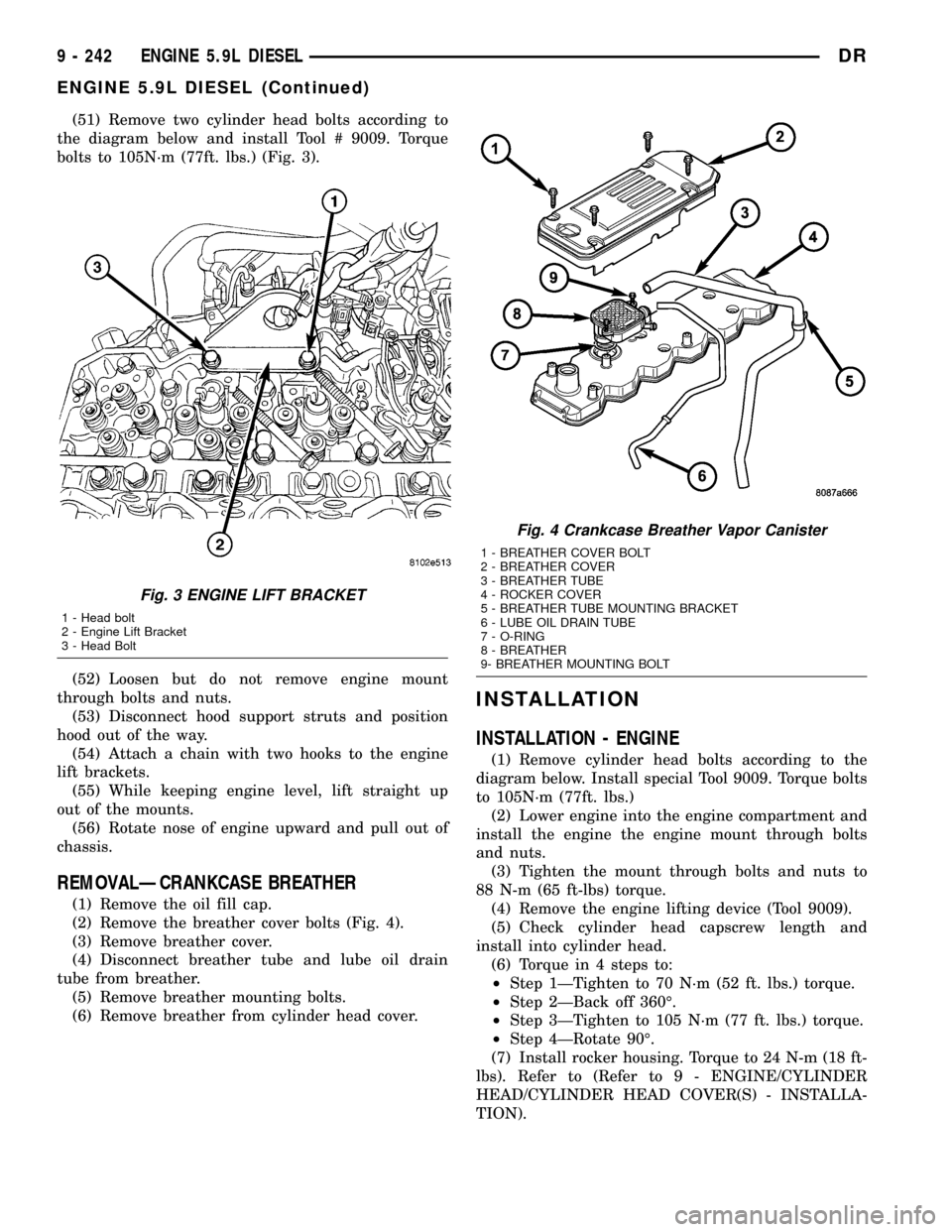
(51) Remove two cylinder head bolts according to
the diagram below and install Tool # 9009. Torque
bolts to 105N´m (77ft. lbs.) (Fig. 3).
(52) Loosen but do not remove engine mount
through bolts and nuts.
(53) Disconnect hood support struts and position
hood out of the way.
(54) Attach a chain with two hooks to the engine
lift brackets.
(55) While keeping engine level, lift straight up
out of the mounts.
(56) Rotate nose of engine upward and pull out of
chassis.
REMOVALÐCRANKCASE BREATHER
(1) Remove the oil fill cap.
(2) Remove the breather cover bolts (Fig. 4).
(3) Remove breather cover.
(4) Disconnect breather tube and lube oil drain
tube from breather.
(5) Remove breather mounting bolts.
(6) Remove breather from cylinder head cover.
INSTALLATION
INSTALLATION - ENGINE
(1) Remove cylinder head bolts according to the
diagram below. Install special Tool 9009. Torque bolts
to 105N´m (77ft. lbs.)
(2) Lower engine into the engine compartment and
install the engine the engine mount through bolts
and nuts.
(3) Tighten the mount through bolts and nuts to
88 N-m (65 ft-lbs) torque.
(4) Remove the engine lifting device (Tool 9009).
(5) Check cylinder head capscrew length and
install into cylinder head.
(6) Torque in 4 steps to:
²Step 1ÐTighten to 70 N´m (52 ft. lbs.) torque.
²Step 2ÐBack off 360É.
²Step 3ÐTighten to 105 N´m (77 ft. lbs.) torque.
²Step 4ÐRotate 90É.
(7) Install rocker housing. Torque to 24 N-m (18 ft-
lbs). Refer to (Refer to 9 - ENGINE/CYLINDER
HEAD/CYLINDER HEAD COVER(S) - INSTALLA-
TION).
Fig. 3 ENGINE LIFT BRACKET
1 - Head bolt
2 - Engine Lift Bracket
3 - Head Bolt
Fig. 4 Crankcase Breather Vapor Canister
1 - BREATHER COVER BOLT
2 - BREATHER COVER
3 - BREATHER TUBE
4 - ROCKER COVER
5 - BREATHER TUBE MOUNTING BRACKET
6 - LUBE OIL DRAIN TUBE
7 - O-RING
8 - BREATHER
9- BREATHER MOUNTING BOLT
9 - 242 ENGINE 5.9L DIESELDR
ENGINE 5.9L DIESEL (Continued)
Page 1472 of 2627
Filter Removal
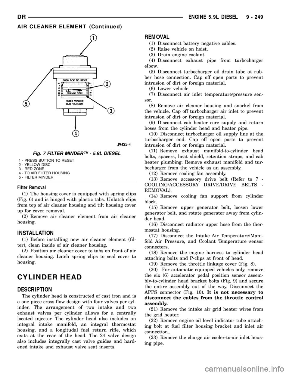
(1) The housing cover is equipped with spring clips
(Fig. 6) and is hinged with plastic tabs. Unlatch clips
from top of air cleaner housing and tilt housing cover
up for cover removal.
(2) Remove air cleaner element from air cleaner
housing.
INSTALLATION
(1) Before installing new air cleaner element (fil-
ter), clean inside of air cleaner housing.
(2) Position air cleaner cover to tabs on front of air
cleaner housing. Latch spring clips to seal cover to
housing.
CYLINDER HEAD
DESCRIPTION
The cylinder head is constructed of cast iron and is
a one piece cross flow design with four valves per cyl-
inder. The arrangement of two intake and two
exhaust valves per cylinder allows for a centrally
located injector. The cylinder head also includes an
integral intake manifold, an integral thermostat
housing, and a longitudal fuel return rifle, which
exits at the rear of the head. The 24 valve design
also includes integrally cast valve guides and hard-
ened intake and exhaust valve seat inserts.
REMOVAL
(1) Disconnect battery negative cables.
(2) Raise vehicle on hoist.
(3) Drain engine coolant.
(4) Disconnect exhaust pipe from turbocharger
elbow.
(5) Disconnect turbocharger oil drain tube at rub-
ber hose connection. Cap off open ports to prevent
intrusion of dirt or foreign material.
(6) Lower vehicle.
(7) Disconnect air inlet temperature/pressure sen-
sor.
(8) Remove air cleaner housing and snorkel from
the vehicle. Cap off turbocharger air inlet to prevent
intrusion of dirt or foreign material.
(9) Disconnect cab heater core supply and return
hoses from the cylinder head and heater pipe.
(10) Disconnect turbocharger oil supply line at the
turbocharger end. Cap off open ports to prevent
intrusion of dirt or foreign material.
(11) Remove exhaust manifold-to-cylinder head
bolts, spacers, heat shield, retention straps, and cab
heater plumbing. Remove exhaust manifold and tur-
bocharger from the vehicle as an assembly.
(12) Remove cooling fan assembly.
(13) Remove accessory drive belt (Refer to 7 -
COOLING/ACCESSORY DRIVE/DRIVE BELTS -
REMOVAL).
(14) Remove cooling fan support from cylinder
block.
(15) Remove upper generator bolt, loosen lower
generator bolt, and rotate generator away from cylin-
der head.
(16) Disconnect radiator upper hose from the ther-
mostat housing.
(17) Disconnect the Intake Air Temperature/Mani-
fold Air Pressure, and Coolant Temperature sensor
connectors.
(18) Remove the engine harness to cylinder head
attaching bolts and P-clips at front of head.
(19) Remove the throttle linkage cover (Fig. 8).
(20) For automatic equipped vehicles only, remove
the six (6) accelerator pedal position sensor assem-
bly-to-cylinder head bracket bolts (Fig. 9) and secure
the entire assembly out of the way. Disconnect the
APPS connector (Fig. 10).It is not necessary to
disconnect the cables from the throttle control
assembly.
(21) Remove the intake air grid heater wires from
the grid heater.
(22) Remove engine oil level indicator tube attach-
ing bolt at fuel filter housing bracket and inlet air
connection..
(23) Remove the charge air cooler-to-air inlet hous-
ing pipe.
Fig. 7 FILTER MINDERŸ - 5.9L DIESEL
1 - PRESS BUTTON TO RESET
2 - YELLOW DISC
3 - RED ZONE
4 - TO AIR FILTER HOUSING
5 - FILTER MINDER
DRENGINE 5.9L DIESEL 9 - 249
AIR CLEANER ELEMENT (Continued)
Page 1477 of 2627
(9) Install rocker housing and bolts. Tighten to 24
Nm (18 lb. ft.).
(10) Install fuel injector(Refer to 14 - FUEL SYS-
TEM/FUEL INJECTION/FUEL INJECTOR -
INSTALLATION).
(11) Install injector harness nuts. Tighten to 1.25
Nm (11 lb. in.).
(12) Install cylinder head cover (Refer to 9 -
ENGINE/CYLINDER HEAD/CYLINDER HEAD
COVER(S) - INSTALLATION).
(13) Install wire harness P-clip to cylinder head
behind filter housing 24 N´m (18 ft. lbs.).
(14) Connect the IAT/MAP sensor connector.
(15) Install the fuel filter canister assembly and
torque mounting bolts to 24 N´m (18 ft. lbs.).
(16) Connect fuel lift pump, WIF sensor, and fuel
heater.
(17) Remove the engine lift bracket at rear of cyl-
inder head.
CAUTION: Failure to follow procedure will result in
fuel leaks and/or fuel system failure.
(18)Install the fuel rail and high pressure
fuel lines as follows:
(a) Hand tighten fuel rail bolts.
(b) Hand tighten fuel drain line to pressure lim-
iting valve. Hand tighten banjo bolt at fuel filter
housing.
(c) Hand tighten fuel rail-to-cylinder head high
pressure fuel lines.(d) Install fuel line brace bolts-to-intake mani-
fold finger tight.
(e) Hand tighten fuel pump to fuel rail line.
(f) Torque fuel line nuts at cylinder head to 30
Nm ( 22 ft. lbs.).
(g) Torque fuel line nuts at fuel rail to 30 Nm
(22 ft. lbs.)
(h) Using a back up wrench, torque fuel pump to
fuel rail line to 37 Nm (27 ft. lbs.). At injection
pump.
(i) Torque fuel pump to fuel rail line to 37 Nm
(27 ft. lbs.) at fuel rail.
(j) Torque fuel drain banjo bolt at pressure lim-
iting valve and front of fuel filter housing to 24 Nm
(18 ft. lbs.).
(k) Torque fuel line brace bolts to 24 N´m (18 ft.
lbs.).
(l) Torque rail bolts to 24 Nm (18 ft. lbs.).
(m) Connect fuel pressure sensor.
(19) Install the engine lift bracket at the rear of
cylinder head. Torque to 77 N´m (57 ft. lbs.).
(20) Reposition number 6 fuel line shield and
torque to 43 N´m (32 ft. lbs.).
(21) Install the fuel filter to injection pump low
pressure line. Inspect and replace sealing washers if
necessary. Torque banjo bolts to 24 N´m (18 ft. lbs.).
(22) Connect fuel return line at back of cylinder
head hand tight.
(23) Connect fuel return line at filter housing hand
tight.
(24) Torque banjo connections at cylinder head and
fuel filter housing to 24 Nm (18 ft. lbs.)
(25) Install bracket to rear of filter housing.
Torque to 24 Nm (18 ft. lbs.).
(26) Using new gaskets, install the intake grid
heater and air inlet housing. Torque bolts to 24 N´m
(18 ft. lbs.).
(27) Install wire harness P-clip and push on clip to
air inlet housing.
(28) Connect engine oil level indicator tube at fuel
filter housing and at air inlet housing.
(29) Connect the APPS connector.
(30) Install the APPS assembly to the cylinder
head bracket and torque bolts to 24 N´m (18 ft. lbs.).
(31) Install the throttle linkage cover.
(32) Install the charge air cooler-to-air inlet hous-
ing duct assembly. Torque all clamps to 11 N´m (100
in. lbs.).
(33) Connect intake grid heater wires.
(34) Secure engine harness to front of cylinder
head with bolt at four locations.
(35) Connect engine coolant temperature sensor
connector.
(36) Connect radiator upper hose to thermostat
housing.
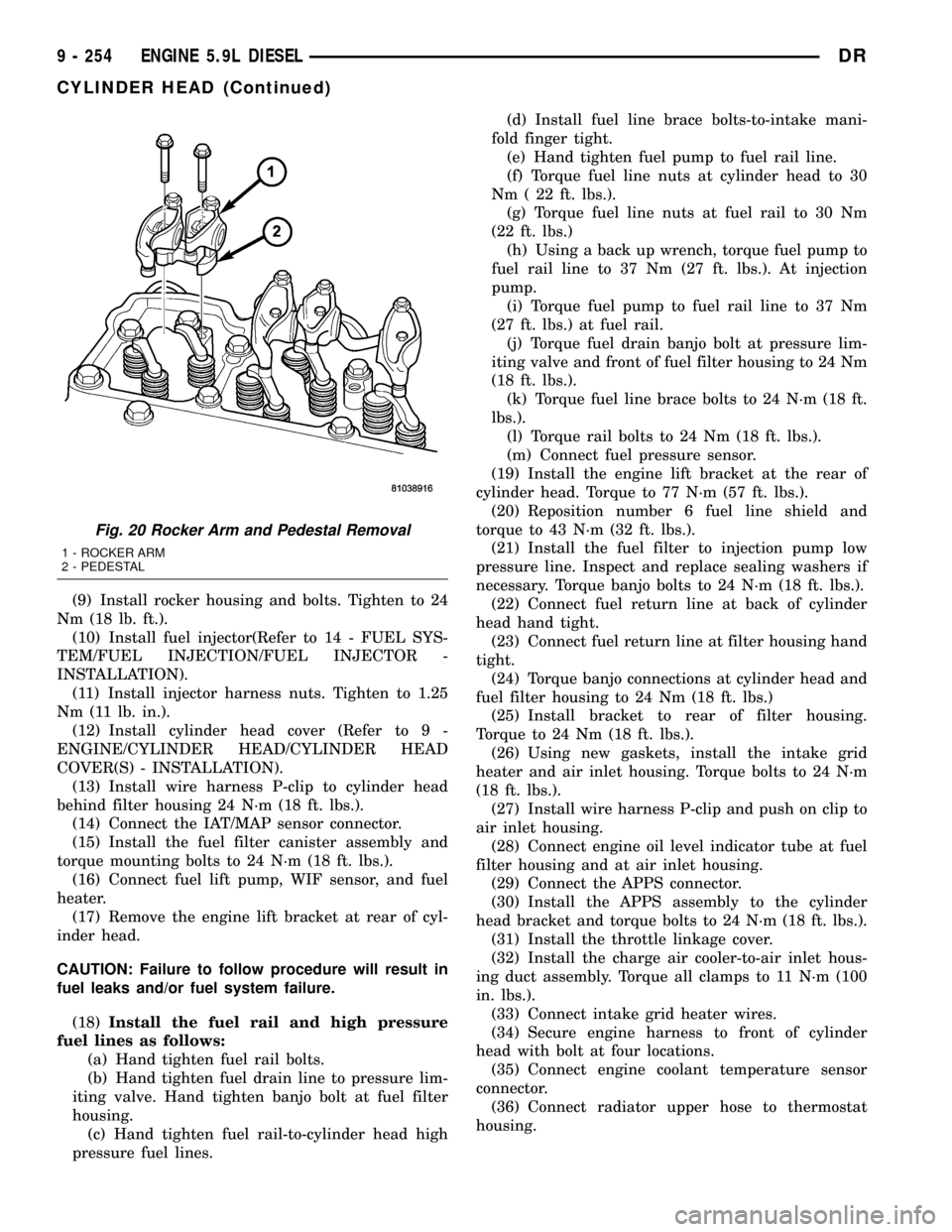
Fig. 20 Rocker Arm and Pedestal Removal
1 - ROCKER ARM
2 - PEDESTAL
9 - 254 ENGINE 5.9L DIESELDR
CYLINDER HEAD (Continued)
Page 1500 of 2627
(7) Install the flywheel or converter drive plate.
Tighten the bolts to 137 N´m (101 ft. lbs.) torque.
(8) Install the clutch cover and disc (if equipped)
(Refer to 6 - CLUTCH/CLUTCH DISC - INSTALLA-
TION).
(9) Install the transmission and transfer case (if
equipped).
(10) Lower vehicle.
(11) Connect battery negative cables.
(12) Check engine oil level and adjust, if necessary.
(13) Start engine and check for oil leaks.
CRANKSHAFT REAR OIL SEAL
RETAINER
REMOVAL
(1) Disconnect the battery negative cables.
(2) Raise vehicle on hoist.
(3) Remove the oil pan drain plug and drain the
engine oil. Re-install plug and torque to 50 N´m (44
ft. lbs.) torque.
(4) Remove transmission and transfer case (if
equipped) from vehicle.
(5)
Remove flywheel or torque converter drive plate.
(6) Disconnect starter cables from starter motor.
(7) Remove starter motor (Refer to 8 - ELECTRI-
CAL/STARTING/STARTER MOTOR - REMOVAL)
and transmission adapter plate assembly.
(8) Remove four (4) oil pan rear bolts. Slide a
feeler gauge between the seal retainer and oil pan
gasket to break the seal.(9) Remove the six (6) retainer-to-block bolts (Fig.
73).
(10) Remove the rear seal retainer and gasket
(Fig. 73).
(11) Support the seal retainer and drive out the
crankshaft seal with a hammer and suitable punch.
INSTALLATION
(1) If using the old seal retainer, the crankshaft
seal must be replaced.
(2) Inspect oil pan gasket for nickes or cuts. If gas-
ket is damaged, the oil pan must be removed and
gasket must be replaced. Wipe oil pan gasket dry and
apply light coating of RTV.
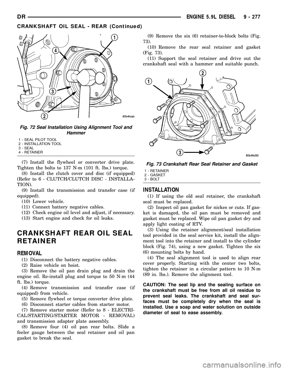
(3) Using the retainer alignment/seal installation
tool provided in the seal service kit, install the align-
ment tool into the retainer and install to the cylinder
block (Fig. 74), using a new gasket. Tighten the six
(6) mounting bolts by hand.
(4) The seal alignment tool is used to align rear
cover properly. Starting with the center two bolts,
tighten the retainer in a circular pattern to 10 N´m
(89 in. lbs.). Remove the alignment tool.
CAUTION: The seal lip and the sealing surface on
the crankshaft must be free from all oil residue to
prevent seal leaks. The crankshaft and seal sur-
faces must be completely dry when the seal is
installed. Use a soap and water solution on outside
diameter of seal to ease assembly.
Fig. 72 Seal Installation Using Alignment Tool and
Hammer
1 - SEAL PILOT TOOL
2 - INSTALLATION TOOL
3 - SEAL
4 - RETAINER
Fig. 73 Crankshaft Rear Seal Retainer and Gasket
1 - RETAINER
2 - GASKET
3 - BOLT
DRENGINE 5.9L DIESEL 9 - 277
CRANKSHAFT OIL SEAL - REAR (Continued)
Page 1515 of 2627
OIL
STANDARD PROCEDURE
STANDARD PROCEDURE - ENGINE OIL LEVEL
CAUTION: Do not overfill crankcase with engine oil,
oil foaming and oil pressure loss can result.
To ensure proper lubrication of an engine, the
engine oil must be maintained at an acceptable level.
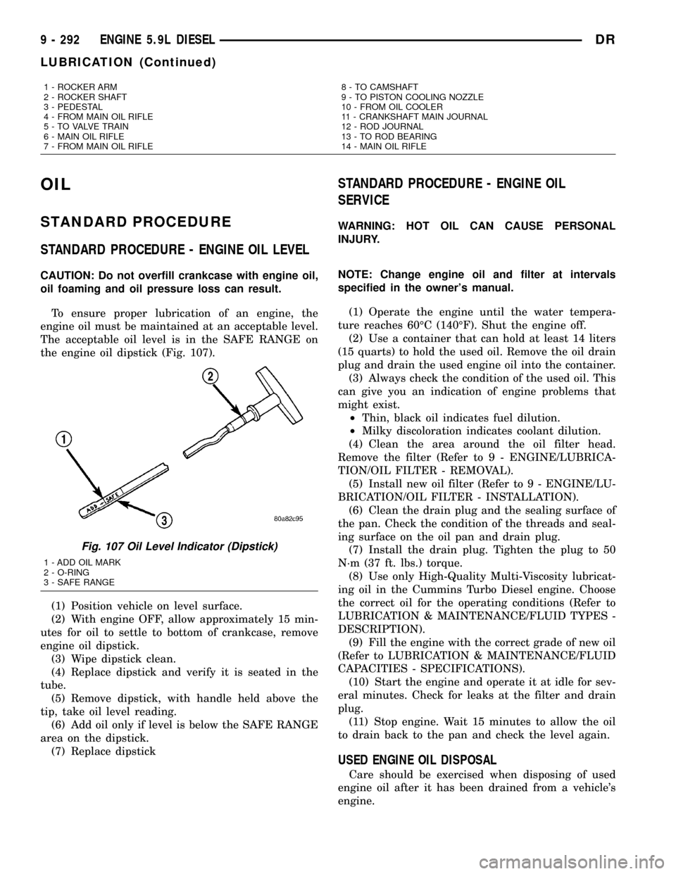
The acceptable oil level is in the SAFE RANGE on
the engine oil dipstick (Fig. 107).
(1) Position vehicle on level surface.
(2) With engine OFF, allow approximately 15 min-
utes for oil to settle to bottom of crankcase, remove
engine oil dipstick.
(3) Wipe dipstick clean.
(4) Replace dipstick and verify it is seated in the
tube.
(5) Remove dipstick, with handle held above the
tip, take oil level reading.
(6) Add oil only if level is below the SAFE RANGE
area on the dipstick.
(7) Replace dipstick
STANDARD PROCEDURE - ENGINE OIL
SERVICE
WARNING: HOT OIL CAN CAUSE PERSONAL
INJURY.
NOTE: Change engine oil and filter at intervals
specified in the owner's manual.
(1) Operate the engine until the water tempera-
ture reaches 60ÉC (140ÉF). Shut the engine off.
(2) Use a container that can hold at least 14 liters
(15 quarts) to hold the used oil. Remove the oil drain
plug and drain the used engine oil into the container.
(3) Always check the condition of the used oil. This
can give you an indication of engine problems that
might exist.
²Thin, black oil indicates fuel dilution.
²Milky discoloration indicates coolant dilution.
(4) Clean the area around the oil filter head.
Remove the filter (Refer to 9 - ENGINE/LUBRICA-
TION/OIL FILTER - REMOVAL).
(5) Install new oil filter (Refer to 9 - ENGINE/LU-
BRICATION/OIL FILTER - INSTALLATION).
(6) Clean the drain plug and the sealing surface of
the pan. Check the condition of the threads and seal-
ing surface on the oil pan and drain plug.
(7) Install the drain plug. Tighten the plug to 50
N´m (37 ft. lbs.) torque.
(8) Use only High-Quality Multi-Viscosity lubricat-
ing oil in the Cummins Turbo Diesel engine. Choose
the correct oil for the operating conditions (Refer to
LUBRICATION & MAINTENANCE/FLUID TYPES -
DESCRIPTION).
(9) Fill the engine with the correct grade of new oil
(Refer to LUBRICATION & MAINTENANCE/FLUID
CAPACITIES - SPECIFICATIONS).
(10) Start the engine and operate it at idle for sev-
eral minutes. Check for leaks at the filter and drain
plug.
(11) Stop engine. Wait 15 minutes to allow the oil
to drain back to the pan and check the level again.
USED ENGINE OIL DISPOSAL
Care should be exercised when disposing of used
engine oil after it has been drained from a vehicle's
engine.
1 - ROCKER ARM
2 - ROCKER SHAFT
3 - PEDESTAL
4 - FROM MAIN OIL RIFLE
5 - TO VALVE TRAIN
6 - MAIN OIL RIFLE
7 - FROM MAIN OIL RIFLE8 - TO CAMSHAFT
9 - TO PISTON COOLING NOZZLE
10 - FROM OIL COOLER
11 - CRANKSHAFT MAIN JOURNAL
12 - ROD JOURNAL
13 - TO ROD BEARING
14 - MAIN OIL RIFLE
Fig. 107 Oil Level Indicator (Dipstick)
1 - ADD OIL MARK
2 - O-RING
3 - SAFE RANGE
9 - 292 ENGINE 5.9L DIESELDR
LUBRICATION (Continued)