1998 DODGE RAM 1500 oil level
[x] Cancel search: oil levelPage 569 of 2627

(1) Position the front fog lamp relay to the proper
receptacle in the Power Distribution Center (PDC).
(2) Align the front fog lamp relay terminals with
the terminal cavities in the PDC.
(3) Press firmly and evenly on the top of the front
fog lamp relay until the terminals are fully seated in
the PDC.
(4) Reconnect the battery negative cable.
HAZARD SWITCH
DESCRIPTION
The hazard switch is activated by a push button
located in the multifunction switch on the top of the
steering column between the steering wheel and
instrument cluster.
The hazard warning system allows the vehicle
operator to provide other vehicle operators in the
near proximity an optical indication that the vehicle
is disabled or an obstacle to traffic flow. The hazard
warning system has battery voltage at all times,
regardless of ignition position.
OPERATION
The instrument cluster monitors the multiplexed
multifunction switch operation. When the hazard
warning switch is activated, the instrument cluster
will send a J1850 bus message to the Front Control
Module (FCM), then activate the two turn signal
indicators and audible click in the instrument clus-
ter.
The FCM will then activate the necessary relays in
the Power Distribution Center (PDC) to begin flash-
ing both the front and rear turn signal indicator
lamps.
HEADLAMP
REMOVAL
(1) Disconnect and isolate the negitive battery
cable.
(2) Remove the headlamp unit (Refer to 8 - ELEC-
TRICAL/LAMPS/LIGHTING - EXTERIOR/HEAD-
LAMP UNIT - REMOVAL).
(3) Seperate the socket from the headlamp unit.
INSTALLATION
CAUTION: Do Not Touch the bulb glass with fingers
or other oily surfaces. Reduced bulb life will result.
(1) Install the socket into the headlamp unit.
(2) Install the headlamp unit (Refer to 8 - ELEC-
TRICAL/LAMPS/LIGHTING - EXTERIOR/HEAD-
LAMP UNIT - INSTALLATION).(3) Connect the negitive battery cable.
HEADLAMP SWITCH
DESCRIPTION
The multiplexed headlamp switch is located on the
instrument panel. The headlamp switch controls the
parking lamps, fog lamps and the headlamps. A sep-
arate switch in the module controls the interior
lamps and instrument cluster illumination. This
switch also contains a rheostat for controlling the
illumination level of the cluster lamps.
OPERATION
The multiplexed headlamp switch has an off, park-
ing lamp, fog lamp and a headlamp on position. High
beams are controlled by the multiplexed multifunc-
tion switch on the steering column. The fog lamps
are illuminated by pulling back on the headlamp
switch knob when in the parking lamp or headlamp
ON position.The headlamp switch cannot be
repaired. It must be replaced.
The Instrument Cluster monitors the headlamp
and multifunction switch operation. When the head-
lamp switch is rotated to the parking lamp or On
position the Instrument Cluster sends a J1850 mes-
sage to the Front Control Module, which is mated to
the power distribution center to become the Inte-
grated Control Module, to illuminate the appropriate
bulbs. When the multifunction switch is activated to
the optical horn or high beam position the Instru-
ment Cluster illuminates the high beam indicator
and sends a J1850 message to the Front Control
Module to illuminate the appropriate bulbs.
REMOVAL
WARNING: ON VEHICLES EQUIPPED WITH AIR-
BAGS, DISABLE THE AIRBAG SYSTEM BEFORE
ATTEMPTING ANY STEERING WHEEL, STEERING
COLUMN, OR INSTRUMENT PANEL COMPONENT
DIAGNOSIS OR SERVICE. DISCONNECT AND ISO-
LATE THE BATTERY NEGATIVE (GROUND) CABLE,
THEN WAIT TWO MINUTES FOR THE AIRBAG SYS-
TEM CAPACITOR TO DISCHARGE BEFORE PER-
FORMING FURTHER DIAGNOSIS OR SERVICE. THIS
IS THE ONLY SURE WAY TO DISABLE THE AIRBAG
SYSTEM. FAILURE TO TAKE THE PROPER PRE-
CAUTIONS COULD RESULT IN ACCIDENTAL AIR-
BAG DEPLOYMENT AND POSSIBLE PERSONAL
INJURY.
(1) Disconnect and isolate the battery negative
cable.
8L - 14 LAMPS/LIGHTING - EXTERIORDR
FOG LAMP RELAY (Continued)
Page 744 of 2627

8W-02 COMPONENT INDEX
Component Page
A/C Compressor Clutch................. 8W-42
A/C Compressor Clutch Relay............ 8W-42
A/C Pressure Transducer................ 8W-42
A/C-Heater Control.................... 8W-42
Accelerator Pedal Position Sensor......... 8W-30
Adjustable Pedal Motor................. 8W-30
Adjustable Pedal Relay................. 8W-30
Adjustable Pedal Switch................ 8W-30
Airbag Control Module................. 8W-43
Airbag-Squibs........................ 8W-43
Airbag-Curtains....................... 8W-43
Airbag-Passenger On/Off Switch.......... 8W-43
Ambient Temperature Sensor............ 8W-49
Amplifier Audio....................... 8W-47
Ashtray Lamp........................ 8W-44
Auto Shut Down Relay................. 8W-30
Automatic Day/Night Mirror.......... 8W-49, 55
Auxiliary Battery..................... 8W-20
Backup Lamp Switch.................. 8W-51
Battery............................. 8W-20
Battery Temperature Sensor............. 8W-30
Blend Door Actuators.................. 8W-42
Blower Motor......................... 8W-42
Blower Motor Resistor Block............. 8W-42
Brake Fluid Level Switch............ 8W-34, 35
Brake Lamp Switch.................... 8W-33
Brake Transmission Shift Interlock
Solenoid........................... 8W-40
Camshaft Position Sensor............... 8W-30
Capacitor............................ 8W-30
Center High Mounted Stop Lamp-
Aftermarket........................ 8W-51
Center High Mounted Stop Lamp/Cargo
Lamp.......................... 8W-44, 51
Cigar Lighter Outlet................... 8W-41
Circuit Breaker....................... 8W-10
Clearance Lamps...................... 8W-50
Clockspring................. 8W-33, 41, 43, 47
Clutch Interlock Brake Switch........... 8W-21
Coil On Plugs........................ 8W-30
Compass/Mini-Trip Computer............ 8W-49
Condenser Fan....................... 8W-42
Condenser Fan Relay.................. 8W-42
Controller Antilock Brake............ 8W-34, 35
Crankshaft Position Sensor.............. 8W-30
Cylinder Lock Switch-Driver............. 8W-61
Data Link Connector................... 8W-18
Data Link Connector-Engine............. 8W-18
Dome Lamp....................... 8W-44, 49
Door Ajar Switches.................... 8W-40
Door Lock Motor/Ajar Switches........ 8W-40, 61
Door Lock Switch-Passenger............. 8W-61Component Page
Door Module................... 8W-60, 61, 62
EGR Solenoid........................ 8W-30
Electric Backlight..................... 8W-48
Electric Brake Provision................ 8W-54
Electronic Throttle Control Module........ 8W-30
Engine Control Module................. 8W-30
Engine Coolant Temperature Sensor....... 8W-30
Engine Oil Pressure Switch.............. 8W-30
EVAP/Purge Solenoid.................. 8W-30
Evaporator Temperature Sensor.......... 8W-42
Fender Lamps........................ 8W-51
Fog Lamp Relay...................... 8W-50
Fog Lamps.......................... 8W-50
Front Control Module.................. 8W-10
Fuel Control Actuator.................. 8W-30
Fuel Heater.......................... 8W-30
Fuel Heater Relay..................... 8W-30
Fuel Injector Packs.................... 8W-30
Fuel Injectors........................ 8W-30
Fuel Pump Module.................... 8W-30
Fuel Pump Motor..................... 8W-30
Fuel Pump Relay...................... 8W-30
Fuses............................ 8W-10, 33
Fusible Link......................... 8W-10
Generator........................... 8W-20
Glove Box Lamp And Switch............. 8W-44
Grounds............................ 8W-15
Hands Free Module.................... 8W-55
Headlamp Switch.................. 8W-40, 50
Headlamps.......................... 8W-50
Heated Mirror Relay................... 8W-62
Heated Seat Cushions.................. 8W-63
Horn Relay.......................... 8W-41
Horn Switch......................... 8W-41
Horn-High Note....................... 8W-41
Horn-Low Note....................... 8W-41
Idle Air Control Motor.................. 8W-30
Ignition Switch....................... 8W-10
Inlet Air Temperature Sensor............ 8W-30
Input Speed Sensor.................... 8W-31
Instrument Cluster.................... 8W-40
Intake Air Heater Relays............... 8W-30
Intake Air Temperature Sensor........... 8W-30
Intake Air Temperature/Manifold Absolute
Pressure Sensor..................... 8W-30
Integrated Power Module............... 8W-10
Knock Sensosr........................ 8W-30
License Lamps....................... 8W-51
Lift Pump Motor...................... 8W-30
Line Pressure Sensor................ 8W-30, 31
Lumbar Motors....................... 8W-63
Lumbar Switch....................... 8W-63
DR8W-02 COMPONENT INDEX 8W - 02 - 1
Page 746 of 2627

8W-10 POWER DISTRIBUTION
Component Page
A/C Compressor Clutch....................8W-10-17, 40
A/C Compressor Clutch Relay.................8W-10-17, 40
A/C-Heater Control....................8W-10-42, 43, 49
Adjustable Pedal Relay....................8W-10-15, 32
Adjustable Pedal Switch..................8W-10-15, 32, 42
Airbag Control Module.....................8W-10-42, 44
Airbag-Passenger On/Off Switch.................8W-10-42
Ambient Temperature Sensor.................8W-10-48, 50
Amplifier Audio..........................8W-10-31
Ashtray Lamp...........................8W-10-35
Auto Shut Down Relay....................8W-10-12, 19
Automatic Day/Night Mirror.................8W-10-41, 48
Auxiliary Battery.........................8W-10-12
Backup Lamp Switch.....................8W-10-44, 49
Battery.............................8W-10-12, 19
Blower Motor............................8W-10-52
Brake Lamp Switch....................8W-10-14, 30, 40
Capacitor..............................8W-10-22
Cigar Lighter Outlet........................8W-10-46
Circuit Breaker...........................8W-10-52
Clearance Lamp No. 1.......................8W-10-35
Clearance Lamp No. 2.......................8W-10-35
Clearance Lamp No. 3.......................8W-10-35
Clearance Lamp No. 4.......................8W-10-35
Clearance Lamp No. 5.......................8W-10-35
Clutch Interlock Brake Switch..................8W-10-37
Coil On Plug No. 1.......................8W-10-20, 23
Coil On Plug No. 2.......................8W-10-21, 22
Coil On Plug No. 3.......................8W-10-20, 23
Coil On Plug No. 4.......................8W-10-21, 22
Coil On Plug No. 5.......................8W-10-20, 23
Coil On Plug No. 6.......................8W-10-21, 22
Coil On Plug No. 7.......................8W-10-20, 23
Coil On Plug No. 8.......................8W-10-21, 22
Compass/Mini-Trip Computer...............8W-10-31, 39, 41
Condenser Fan.........................8W-10-18, 45
Condenser Fan Relay.....................8W-10-18, 45
Controller Antilock Brake.................8W-10-14, 28, 44
Data Link Connector......................8W-10-30, 50
Door Lock Switch-Passenger....................8W-10-41
Driver Door Module....................8W-10-15, 32, 52
Electric Backlight.........................8W-10-49
Electric Brake Provision....................8W-10-12, 19
Engine Control Module................8W-10-12, 26, 38, 40
Fender Lamp-Front Left......................8W-10-35
Fender Lamp-Front Right.....................8W-10-35
Fender Lamp-Rear Left......................8W-10-35
Fender Lamp-Rear Right.....................8W-10-35
Fog Lamp Relay........................8W-10-16, 36
Fog Lamp-Left...........................8W-10-36
Fog Lamp-Right..........................8W-10-36
Front Control Module . 8W-10-13, 26, 29, 30, 32, 33, 34, 36, 47, 48, 50, 51
Fuel Heater............................8W-10-53
Fuel Heater Relay.....................8W-10-18, 40, 53
Fuel Injector No. 1.......................8W-10-23, 24
Fuel Injector No. 2.......................8W-10-21, 22
Fuel Injector No. 3.......................8W-10-23, 24
Fuel Injector No. 4.......................8W-10-21, 22
Fuel Injector No. 5.......................8W-10-23, 24
Fuel Injector No. 6.......................8W-10-21, 22
Fuel Injector No. 7.......................8W-10-23, 24
Fuel Injector No. 8.......................8W-10-21, 22
Fuel Pump Module.......................8W-10-17, 39
Fuel Pump Relay......................8W-10-17, 39, 40
Fuse 1.............................8W-10-12, 19
Fuse 2...........................8W-10-12, 13, 19
Fuse 3.............................8W-10-13, 25
Fuse 4.............................8W-10-13, 25
Fuse 5.......................8W-10-12, 13, 14, 26, 27
Fuse 6...........................8W-10-13, 14, 28
Fuse 7.............................8W-10-14, 28
Fuse 8.............................8W-10-15, 29
Fuse 9.............................8W-10-13, 25
Fuse 10.............................8W-10-13, 25
Fuse 11...........................8W-10-13, 14, 30
Fuse 12...........................8W-10-18, 45, 53
Fuse 13.............................8W-10-13, 30
Fuse 14.............................8W-10-15, 37
Fuse 15...........................8W-10-16, 17, 34
Fuse 16.............................8W-10-17, 40
Fuse 17...........................8W-10-17, 18, 39
Fuse 18.............................8W-10-14, 30
Fuse 19.............................8W-10-14, 31
Fuse 20.............................8W-10-13, 25
Fuse 21.............................8W-10-14, 31
Fuse 22.............................8W-10-14, 31
Fuse 23.............................8W-10-14, 31
Fuse 24.............................8W-10-14, 30Component Page
Fuse 25.............................8W-10-14, 31
Fuse 26...............................8W-10-49
Fuse 27...........................8W-10-17, 18, 43
Fuse 28.............................8W-10-40, 41
Fuse 29...............................8W-10-46
Fuse 32.............................8W-10-17, 34
Fuse 33.............................8W-10-17, 34
Fuse 34.............................8W-10-17, 34
Fuse 35...............................8W-10-44
Fuse 36...............................8W-10-43
Fuse 37...............................8W-10-44
Fuse 38.............................8W-10-43, 44
Fuse 40...........................8W-10-15, 16, 32
Fuse 41.............................8W-10-16, 36
Fuse 42.............................8W-10-14, 32
Fuse 43.............................8W-10-14, 32
Fuse 45...........................8W-10-16, 17, 36
Fuse 46...........................8W-10-15, 16, 33
Fuse 47.............................8W-10-16, 33
Fuse 48.............................8W-10-15, 32
Fuse 49.............................8W-10-12, 19
Fuse 50.............................8W-10-26, 40
Fuse 51...........................8W-10-14, 15, 30
Fuse 52.............................8W-10-43, 44
Fuse 53...............................8W-10-41
Fusible Link............................8W-10-12
G104........................8W-10-27, 29, 47, 48, 53
G201................................8W-10-25
Generator..............................8W-10-12
Headlamp Switch.........................8W-10-36
Headlamp-Left...........................8W-10-51
Headlamp-Right..........................8W-10-51
Heated Mirror Relay......................8W-10-18, 43
Horn Relay...........................8W-10-16, 36
Horn-High Note..........................8W-10-36
Horn-Low Note...........................8W-10-36
Ignition Switch...............8W-10-13, 25, 37, 41, 44, 46, 52
Instrument Cluster............8W-10-14, 25, 30, 31, 41, 46, 52
Integrated Power Module . . 8W-10-3, 4, 12, 13, 14, 15, 16, 17, 18, 19, 25,
26, 27, 28, 29, 30, 31, 32, 33, 34, 36, 37, 39, 40, 41, 42, 43, 44, 45, 46,
47, 48, 49, 50, 51, 53
License Lamp-Left.........................8W-10-34
License Lamp-Right........................8W-10-34
Oxygen Sensor Downstream Relay..............8W-10-12, 19
Park Lamp Relay.......................8W-10-17, 34
Park/Turn Signal Lamp-Left Front..............8W-10-34, 47
Park/Turn Signal Lamp-Right Front.............8W-10-34, 47
Passenger Lumbar Switch.....................8W-10-28
Power Mirror-Left.........................8W-10-43
Power Mirror-Right........................8W-10-43
Power Outlet..........................8W-10-14, 31
Power Outlet-Console.....................8W-10-14, 32
Power Seat Switch-Driver.....................8W-10-28
Power Seat Switch-Passenger...................8W-10-28
Power Window Circuit Breaker..................8W-10-52
Powertrain Control Module . . 8W-10-18, 19, 22, 27, 31, 37, 39, 40, 45, 52
PTCNo.1 .........................8W-10-39, 40, 41
PTCNo.2 .............................8W-10-46
PTCNo.5 .............................8W-10-33
Radio..............................8W-10-30, 46
Rear Window Defogger Relay...................8W-10-49
Seat Belt Tensioner Reducer....................8W-10-46
Seat Heater Interface Module...................8W-10-32
Sentry Key Immobilizer Module..............8W-10-31, 39, 40
Starter Motor..........................8W-10-15, 37
Starter Motor Relay......................8W-10-15, 37
Tail/Stop/Turn Signal Lamp-Left...........8W-10-34, 47, 48, 50
Tail/Stop/Turn Signal Lamp-Right..........8W-10-35, 47, 48, 50
Tailgate Lamp...........................8W-10-34
Trailer Tow Connector.................8W-10-16, 17, 33, 34
Trailer Tow Connector-Add On..........8W-10-14, 31, 33, 34, 48
Trailer Tow Left Turn Relay..................8W-10-16, 33
Trailer Tow Right Turn Relay.................8W-10-16, 33
Transfer Case Control Module...............8W-10-14, 32, 37
Transfer Case Selector Switch...................8W-10-41
Transmission Control Relay................8W-10-13, 26, 27
Transmission Range Sensor................8W-10-38, 44, 49
Transmission Solenoid Assembly.................8W-10-26
Transmission Solenoid/TRS Assembly...........8W-10-27, 44, 49
Underhood Lamp..........................8W-10-30
Vistronic Fan Drive........................8W-10-43
Washer Fluid Level Switch....................8W-10-48
Washer Pump Motor-Front....................8W-10-48
Wiper High/Low Relay.....................8W-10-15, 29
Wiper Motor-Front.......................8W-10-29, 48
Wiper On/Off Relay......................8W-10-15, 29
DR8W-10 POWER DISTRIBUTION 8W - 10 - 1
Page 1109 of 2627

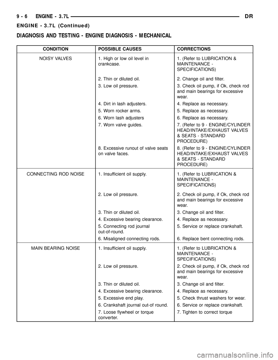
ENGINE CONTROL MODULE C2 (DIESEL) - 50 WAY
CAV CIRCUIT FUNCTION
1- -
2- -
3 K615 18VT/WT INLET AIR TEMPERATURE SENSE
3 K615 18BR/WT (M/T) INLET AIR TEMPERATURE SENSE
4 V35 18VT/OR (A/T) S/C VENT CONTROL
5 K176 18BR/OR INTAKE AIR HEATER RELAY NO 2 CONTROL
6 K174 18BR/YL INTAKE AIR HEATER RELAY NO 1 CONTROL
7 V32 18VT/YL (A/T) SPEED CONTROL SUPPLY
8- -
9 T41 18YL/DB (A/T) PARK/NEUTRAL POSITION SWITCH SENSE (T41)
10 K161 18BR/LB FAN SPEED SENSOR
11 B22 18DG/YL VEHICLE SPEED SENSOR SIGNAL NO. 1
12 G6 18VT/GY OIL PRESSURE SIGNAL
13 T6 18DG (A/T) TOW/HAUL OVERDRIVE OFF SWITCH SENSE
14 T118 18DG (A/T) GOVERNOR PRESSURE SOLENOID CONTROL
15 T9 18DG/TN (A/T) 3-4 SOLENIOD CONTROL
16 D21 18WT/BR SCI TRANSMIT (PCM)
16 D21 18PK (M/T) SCI TRANSMIT
17 - -
18 T38 18YL/BR (A/T) GOVERNOR PRESSURE SENSOR SIGNAL
19 D20 18WT/LG SCI RECEIVE (PCM)
20 A209 16RD FUSED B(+)
21 Z902 16BK GROUND
22 - -
23 F856 18YL/PK 5 VOLT SUPPLY
24 K900 18DB/DG SENSOR GROUND
25 T75 18YL/LB (A/T) TORQUE CONVERTER CLUTCH SOLENOID CONTROL
26 N4 18DB/WT FUEL LEVEL SENSOR SIGNAL
27 - -
28 D25 18WT/VT PCI BUS
29 T54 18DG/OR (A/T) TRANSMISSION TEMPERATURE SENSOR SIGNAL
30 A209 16RD FUSED B(+)
31 T515 18YL/DB (A/T) TRANSMISSION CONTROL RELAY CONTROL
32 F202 18PK/GY FUSED IGNITION SWITCH OUTPUT (RUN-START)
33 K854 18VT/BR (M/T) 5 VOLT SUPPLY
34 V36 18VT/YL (A/T) S/C VACUUM CONTROL
35 K616 18BR/YL INLET AIR PRESSURE SENSE
36 V32 18VT/YL (M/T) SPEED CONTROL SUPPLY
37 B29 18DG/WT BRAKE SWITCH SIGNAL
38 - -
39 - -
40 A209 16RD FUSED B(+)
41 C13 18LB/OR A/C CLUTCH RELAY CONTROL
42 - -
43 K160 18BR/OR PARK LOCKOUT SOLENOID CONTROL
44 T14 18DG/BR (A/T) OUTPUT SPEED SENSOR SIGNAL
45 T13 18DG/VT (A/T) SENSOR GROUND
46 V37 18VT S/C SWITCH NO. 1 SIGNAL
47 K25 18DB/VT BATT TEMP SIGNAL
48 K400 18BR/VT (M/T) APPS NO.2 RETURN
49 Z902 16BK GROUND
50 Z902 16BK GROUND
8W - 80 - 60 8W-80 CONNECTOR PIN-OUTSDR
Page 1229 of 2627

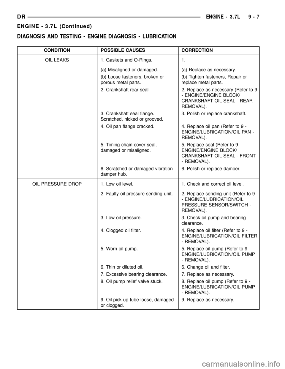
DIAGNOSIS AND TESTING - ENGINE DIAGNOSIS - MECHANICAL
CONDITION POSSIBLE CAUSES CORRECTIONS
NOISY VALVES 1. High or low oil level in
crankcase.1. (Refer to LUBRICATION &
MAINTENANCE -
SPECIFICATIONS)
2. Thin or diluted oil. 2. Change oil and filter.
3. Low oil pressure. 3. Check oil pump, if Ok, check rod
and main bearings for excessive
wear.
4. Dirt in lash adjusters. 4. Replace as necessary.
5. Worn rocker arms. 5. Replace as necessary.
6. Worn lash adjusters 6. Replace as necessary.
7. Worn valve guides. 7. (Refer to 9 - ENGINE/CYLINDER
HEAD/INTAKE/EXHAUST VALVES
& SEATS - STANDARD
PROCEDURE)
8. Excessive runout of valve seats
on valve faces.8. (Refer to 9 - ENGINE/CYLINDER
HEAD/INTAKE/EXHAUST VALVES
& SEATS - STANDARD
PROCEDURE)
CONNECTING ROD NOISE 1. Insufficient oil supply. 1. (Refer to LUBRICATION &
MAINTENANCE -
SPECIFICATIONS)
2. Low oil pressure. 2. Check oil pump, if Ok, check rod
and main bearings for excessive
wear.
3. Thin or diluted oil. 3. Change oil and filter.
4. Excessive bearing clearance. 4. Replace as necessary.
5. Connecting rod journal
out-of-round.5. Service or replace crankshaft.
6. Misaligned connecting rods. 6. Replace bent connecting rods.
MAIN BEARING NOISE 1. Insufficient oil supply. 1. (Refer to LUBRICATION &
MAINTENANCE -
SPECIFICATIONS)
2. Low oil pressure. 2. Check oil pump, if Ok, check rod
and main bearings for excessive
wear.
3. Thin or diluted oil. 3. Change oil and filter.
4. Excessive bearing clearance. 4. Replace as necessary.
5. Excessive end play. 5. Check thrust washers for wear.
6. Crankshaft journal out-of round. 6. Service or replace crankshaft.
7. Loose flywheel or torque
converter.7. Tighten to correct torque
9 - 6 ENGINE - 3.7LDR
ENGINE - 3.7L (Continued)
Page 1230 of 2627

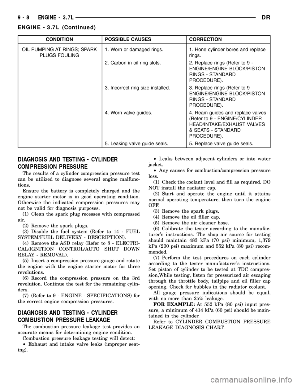
DIAGNOSIS AND TESTING - ENGINE DIAGNOSIS - LUBRICATION
CONDITION POSSIBLE CAUSES CORRECTION
OIL LEAKS 1. Gaskets and O-Rings. 1.
(a) Misaligned or damaged. (a) Replace as necessary.
(b) Loose fasteners, broken or
porous metal parts.(b) Tighten fasteners, Repair or
replace metal parts.
2. Crankshaft rear seal 2. Replace as necessary (Refer to 9
- ENGINE/ENGINE BLOCK/
CRANKSHAFT OIL SEAL - REAR -
REMOVAL).
3. Crankshaft seal flange.
Scratched, nicked or grooved.3. Polish or replace crankshaft.
4. Oil pan flange cracked. 4. Replace oil pan (Refer to 9 -
ENGINE/LUBRICATION/OIL PAN -
REMOVAL).
5. Timing chain cover seal,
damaged or misaligned.5. Replace seal (Refer to 9 -
ENGINE/ENGINE BLOCK/
CRANKSHAFT OIL SEAL - FRONT
- REMOVAL).
6. Scratched or damaged vibration
damper hub.6. Polish or replace damper.
OIL PRESSURE DROP 1. Low oil level. 1. Check and correct oil level.
2. Faulty oil pressure sending unit. 2. Replace sending unit (Refer to 9
- ENGINE/LUBRICATION/OIL
PRESSURE SENSOR/SWITCH -
REMOVAL).
3. Low oil pressure. 3. Check oil pump and bearing
clearance.
4. Clogged oil filter. 4. Replace oil filter (Refer to 9 -
ENGINE/LUBRICATION/OIL FILTER
- REMOVAL).
5. Worn oil pump. 5. Replace oil pump (Refer to 9 -
ENGINE/LUBRICATION/OIL PUMP
- REMOVAL).
6. Thin or diluted oil. 6. Change oil and filter.
7. Excessive bearing clearance. 7. Replace as necessary.
8. Oil pump relief valve stuck. 8. Replace oil pump (Refer to 9 -
ENGINE/LUBRICATION/OIL PUMP
- REMOVAL).
9. Oil pick up tube loose, damaged
or clogged.9. Replace as necessary.
DRENGINE - 3.7L 9 - 7
ENGINE - 3.7L (Continued)
Page 1231 of 2627

CONDITION POSSIBLE CAUSES CORRECTION
OIL PUMPING AT RINGS; SPARK
PLUGS FOULING1. Worn or damaged rings. 1. Hone cylinder bores and replace
rings.
2. Carbon in oil ring slots. 2. Replace rings (Refer to 9 -
ENGINE/ENGINE BLOCK/PISTON
RINGS - STANDARD
PROCEDURE).
3. Incorrect ring size installed. 3. Replace rings (Refer to 9 -
ENGINE/ENGINE BLOCK/PISTON
RINGS - STANDARD
PROCEDURE).
4. Worn valve guides. 4. Ream guides and replace valves
(Refer to 9 - ENGINE/CYLINDER
HEAD/INTAKE/EXHAUST VALVES
& SEATS - STANDARD
PROCEDURE).
5. Leaking valve guide seals. 5. Replace valve guide seals.
DIAGNOSIS AND TESTING - CYLINDER
COMPRESSION PRESSURE
The results of a cylinder compression pressure test
can be utilized to diagnose several engine malfunc-
tions.
Ensure the battery is completely charged and the
engine starter motor is in good operating condition.
Otherwise the indicated compression pressures may
not be valid for diagnosis purposes.
(1) Clean the spark plug recesses with compressed
air.
(2) Remove the spark plugs.
(3) Disable the fuel system (Refer to 14 - FUEL
SYSTEM/FUEL DELIVERY - DESCRIPTION).
(4) Remove the ASD relay (Refer to 8 - ELECTRI-
CAL/IGNITION CONTROL/AUTO SHUT DOWN
RELAY - REMOVAL).
(5) Insert a compression pressure gauge and rotate
the engine with the engine starter motor for three
revolutions.
(6) Record the compression pressure on the 3rd
revolution. Continue the test for the remaining cylin-
ders.
(7) (Refer to 9 - ENGINE - SPECIFICATIONS) for
the correct engine compression pressures.
DIAGNOSIS AND TESTING - CYLINDER
COMBUSTION PRESSURE LEAKAGE
The combustion pressure leakage test provides an
accurate means for determining engine condition.
Combustion pressure leakage testing will detect:
²Exhaust and intake valve leaks (improper seat-
ing).²Leaks between adjacent cylinders or into water
jacket.
²Any causes for combustion/compression pressure
loss.
(1) Check the coolant level and fill as required. DO
NOT install the radiator cap.
(2) Start and operate the engine until it attains
normal operating temperature, then turn the engine
OFF.
(3) Remove the spark plugs.
(4) Remove the oil filler cap.
(5) Remove the air cleaner hose.
(6) Calibrate the tester according to the manufac-
turer's instructions. The shop air source for testing
should maintain 483 kPa (70 psi) minimum, 1,379
kPa (200 psi) maximum and 552 kPa (80 psi) recom-
mended.
(7) Perform the test procedures on each cylinder
according to the tester manufacturer's instructions.
Set piston of cylinder to be tested at TDC compres-
sion,While testing, listen for pressurized air escaping
through the throttle body, tailpipe and oil filler cap
opening. Check for bubbles in the radiator coolant.
All gauge pressure indications should be equal,
with no more than 25% leakage.
FOR EXAMPLE:At 552 kPa (80 psi) input pres-
sure, a minimum of 414 kPa (60 psi) should be main-
tained in the cylinder.
Refer to CYLINDER COMBUSTION PRESSURE
LEAKAGE DIAGNOSIS CHART.
9 - 8 ENGINE - 3.7LDR
ENGINE - 3.7L (Continued)
Page 1255 of 2627

VALVE GUIDE SEALS
DESCRIPTION
The valve guide seals are made of rubber and
incorporate an integral steel valve spring seat. The
integral garter spring maintains consistent lubrica-
tion control to the valve stems.
VALVE SPRINGS
DESCRIPTION
The valve springs are made from high strength
chrome silicon steel. The springs are NOT common
for intake and exhaust applications. The exhaust
spring has an external damper. The valve spring seat
is integral with the valve stem seal, which is a posi-
tive type seal to control lubrication.
REMOVAL
(1) Remove the cylinder head cover(Refer to 9 -
ENGINE/CYLINDER HEAD/CYLINDER HEAD
COVER(S) - REMOVAL).
(2) Using Special Tool 8516 Valve Spring Compres-
sor, remove the rocker arms and the hydraulic lash
adjusters.
(3) Remove the spark plug for the cylinder the
valve spring and seal are to be removed from.
(4) Apply shop air to the cylinder to hold the
valves in place when the spring is removed.
NOTE: All six valve springs and seals are removed
in the same manner; this procedure only covers
one valve seal and valve spring.
(5) Using Special Tool 8387 Valve Spring Compres-
sor, compress the valve spring.
NOTE: It may be necessary to tap the top of the
valve spring to loosen the spring retainers locks
enough to be removed.
(6) Remove the two spring retainer lock halves.
NOTE: the valve spring is under tension use care
when releasing the valve spring compressor.
(7) Remove the valve spring compressor.
NOTE: The valve springs are NOT common between
intake and exhaust.
(8) Remove the spring retainer, and the spring.
(9) Remove the valve stem seal.
NOTE: The valve stem seals are common between
intake and exhaust.
INSTALLATION
NOTE: All six valve springs and seals are removed
in the same manner; this procedure only covers
one valve seal and valve spring.
(1) Apply shop air to the cylinder to hold the
valves in place while the spring is installed.
NOTE: The valve stem seals are common between
intake and exhaust.
(2) Install the valve stem seal.
NOTE: The valve springs are NOT common between
intake and exhaust.
(3) Install the spring retainer, and the spring.
(4) Using Special Tool 8387 Valve Spring Compres-
sor, compress the valve spring.
(5) Install the two spring retainer lock halves.
NOTE: the valve spring is under tension use care
when releasing the valve spring compressor.
(6) Remove the valve spring compressor.
(7) Disconnect the shop air to the cylinder.
(8) Install the spark plug for the cylinder the valve
spring and seal was installed on.
(9) Using Special Tool 8516 Valve Spring Compres-
sor, install the rocker arms and the hydraulic lash
adjusters.
(10) Install the cylinder head cover(Refer to 9 -
ENGINE/CYLINDER HEAD/CYLINDER HEAD
COVER(S) - INSTALLATION).
CYLINDER HEAD - RIGHT
DIAGNOSIS AND TESTING - HYDRAULIC LASH
ADJUSTER
A tappet-like noise may be produced from several
items. Check the following items.
(1) Engine oil level too high or too low. This may
cause aerated oil to enter the adjusters and cause
them to be spongy.
(2) Insufficient running time after rebuilding cylin-
der head. Low speed running up to 1 hour may be
required.
(3) Turn engine off and let set for a few minutes
before restarting. Repeat this several times after
engine has reached normal operating temperature.
(4) Low oil pressure.
(5) The oil restrictor in cylinder head gasket or the
oil passage to the cylinder head is plugged with
debris.
9 - 32 ENGINE - 3.7LDR