1998 DODGE RAM 1500 Driver door
[x] Cancel search: Driver doorPage 1158 of 2627

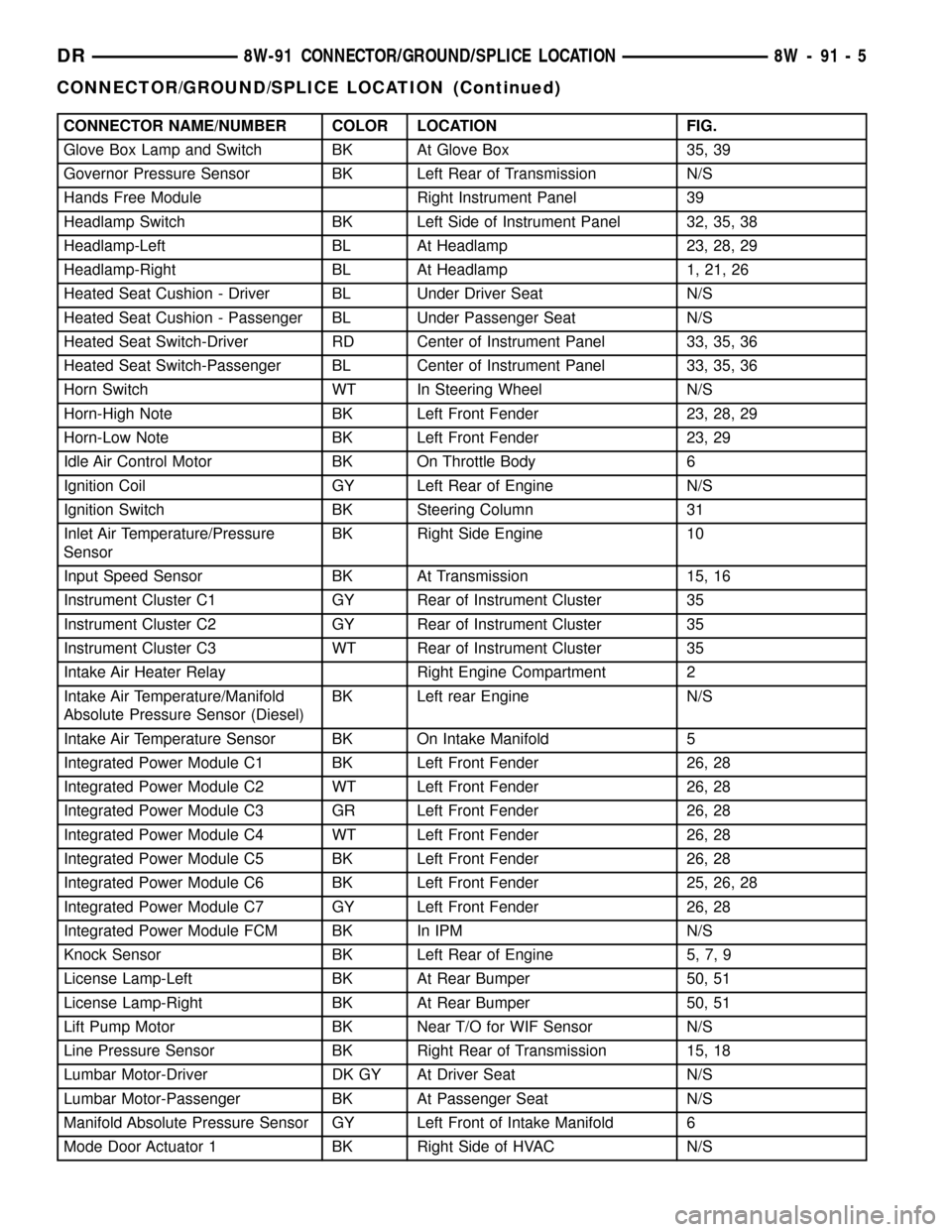
CONNECTOR NAME/NUMBER COLOR LOCATION FIG.
Glove Box Lamp and Switch BK At Glove Box 35, 39
Governor Pressure Sensor BK Left Rear of Transmission N/S
Hands Free Module Right Instrument Panel 39
Headlamp Switch BK Left Side of Instrument Panel 32, 35, 38
Headlamp-Left BL At Headlamp 23, 28, 29
Headlamp-Right BL At Headlamp 1, 21, 26
Heated Seat Cushion - Driver BL Under Driver Seat N/S
Heated Seat Cushion - Passenger BL Under Passenger Seat N/S
Heated Seat Switch-Driver RD Center of Instrument Panel 33, 35, 36
Heated Seat Switch-Passenger BL Center of Instrument Panel 33, 35, 36
Horn Switch WT In Steering Wheel N/S
Horn-High Note BK Left Front Fender 23, 28, 29
Horn-Low Note BK Left Front Fender 23, 29
Idle Air Control Motor BK On Throttle Body 6
Ignition Coil GY Left Rear of Engine N/S
Ignition Switch BK Steering Column 31
Inlet Air Temperature/Pressure
SensorBK Right Side Engine 10
Input Speed Sensor BK At Transmission 15, 16
Instrument Cluster C1 GY Rear of Instrument Cluster 35
Instrument Cluster C2 GY Rear of Instrument Cluster 35
Instrument Cluster C3 WT Rear of Instrument Cluster 35
Intake Air Heater Relay Right Engine Compartment 2
Intake Air Temperature/Manifold
Absolute Pressure Sensor (Diesel)BK Left rear Engine N/S
Intake Air Temperature Sensor BK On Intake Manifold 5
Integrated Power Module C1 BK Left Front Fender 26, 28
Integrated Power Module C2 WT Left Front Fender 26, 28
Integrated Power Module C3 GR Left Front Fender 26, 28
Integrated Power Module C4 WT Left Front Fender 26, 28
Integrated Power Module C5 BK Left Front Fender 26, 28
Integrated Power Module C6 BK Left Front Fender 25, 26, 28
Integrated Power Module C7 GY Left Front Fender 26, 28
Integrated Power Module FCM BK In IPM N/S
Knock Sensor BK Left Rear of Engine 5, 7, 9
License Lamp-Left BK At Rear Bumper 50, 51
License Lamp-Right BK At Rear Bumper 50, 51
Lift Pump Motor BK Near T/O for WIF Sensor N/S
Line Pressure Sensor BK Right Rear of Transmission 15, 18
Lumbar Motor-Driver DK GY At Driver Seat N/S
Lumbar Motor-Passenger BK At Passenger Seat N/S
Manifold Absolute Pressure Sensor GY Left Front of Intake Manifold 6
Mode Door Actuator 1 BK Right Side of HVAC N/S
DR8W-91 CONNECTOR/GROUND/SPLICE LOCATION 8W - 91 - 5
CONNECTOR/GROUND/SPLICE LOCATION (Continued)
Page 1159 of 2627

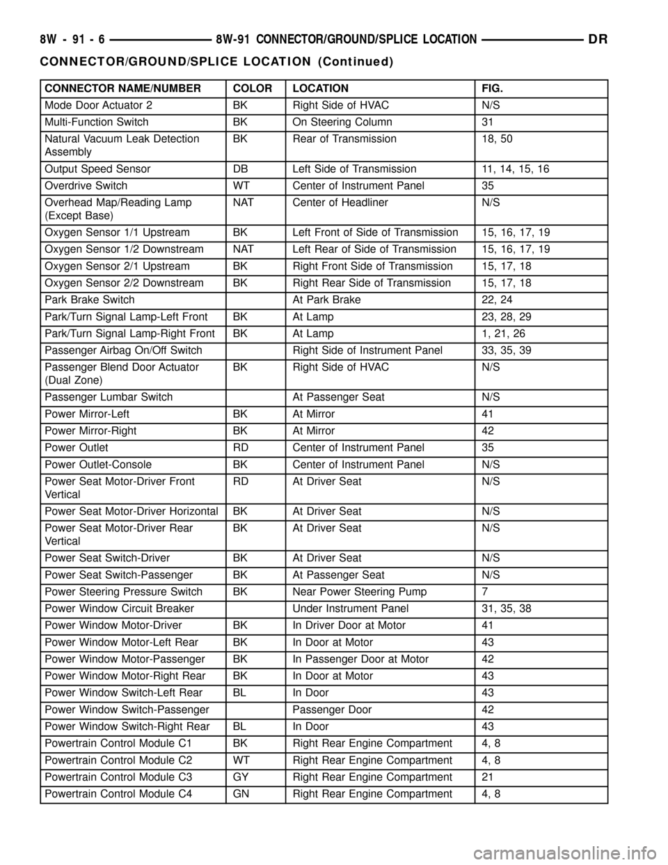
CONNECTOR NAME/NUMBER COLOR LOCATION FIG.
Mode Door Actuator 2 BK Right Side of HVAC N/S
Multi-Function Switch BK On Steering Column 31
Natural Vacuum Leak Detection
AssemblyBK Rear of Transmission 18, 50
Output Speed Sensor DB Left Side of Transmission 11, 14, 15, 16
Overdrive Switch WT Center of Instrument Panel 35
Overhead Map/Reading Lamp
(Except Base)NAT Center of Headliner N/S
Oxygen Sensor 1/1 Upstream BK Left Front of Side of Transmission 15, 16, 17, 19
Oxygen Sensor 1/2 Downstream NAT Left Rear of Side of Transmission 15, 16, 17, 19
Oxygen Sensor 2/1 Upstream BK Right Front Side of Transmission 15, 17, 18
Oxygen Sensor 2/2 Downstream BK Right Rear Side of Transmission 15, 17, 18
Park Brake Switch At Park Brake 22, 24
Park/Turn Signal Lamp-Left Front BK At Lamp 23, 28, 29
Park/Turn Signal Lamp-Right Front BK At Lamp 1, 21, 26
Passenger Airbag On/Off Switch Right Side of Instrument Panel 33, 35, 39
Passenger Blend Door Actuator
(Dual Zone)BK Right Side of HVAC N/S
Passenger Lumbar Switch At Passenger Seat N/S
Power Mirror-Left BK At Mirror 41
Power Mirror-Right BK At Mirror 42
Power Outlet RD Center of Instrument Panel 35
Power Outlet-Console BK Center of Instrument Panel N/S
Power Seat Motor-Driver Front
VerticalRD At Driver Seat N/S
Power Seat Motor-Driver Horizontal BK At Driver Seat N/S
Power Seat Motor-Driver Rear
VerticalBK At Driver Seat N/S
Power Seat Switch-Driver BK At Driver Seat N/S
Power Seat Switch-Passenger BK At Passenger Seat N/S
Power Steering Pressure Switch BK Near Power Steering Pump 7
Power Window Circuit Breaker Under Instrument Panel 31, 35, 38
Power Window Motor-Driver BK In Driver Door at Motor 41
Power Window Motor-Left Rear BK In Door at Motor 43
Power Window Motor-Passenger BK In Passenger Door at Motor 42
Power Window Motor-Right Rear BK In Door at Motor 43
Power Window Switch-Left Rear BL In Door 43
Power Window Switch-Passenger Passenger Door 42
Power Window Switch-Right Rear BL In Door 43
Powertrain Control Module C1 BK Right Rear Engine Compartment 4, 8
Powertrain Control Module C2 WT Right Rear Engine Compartment 4, 8
Powertrain Control Module C3 GY Right Rear Engine Compartment 21
Powertrain Control Module C4 GN Right Rear Engine Compartment 4, 8
8W - 91 - 6 8W-91 CONNECTOR/GROUND/SPLICE LOCATIONDR
CONNECTOR/GROUND/SPLICE LOCATION (Continued)
Page 1160 of 2627

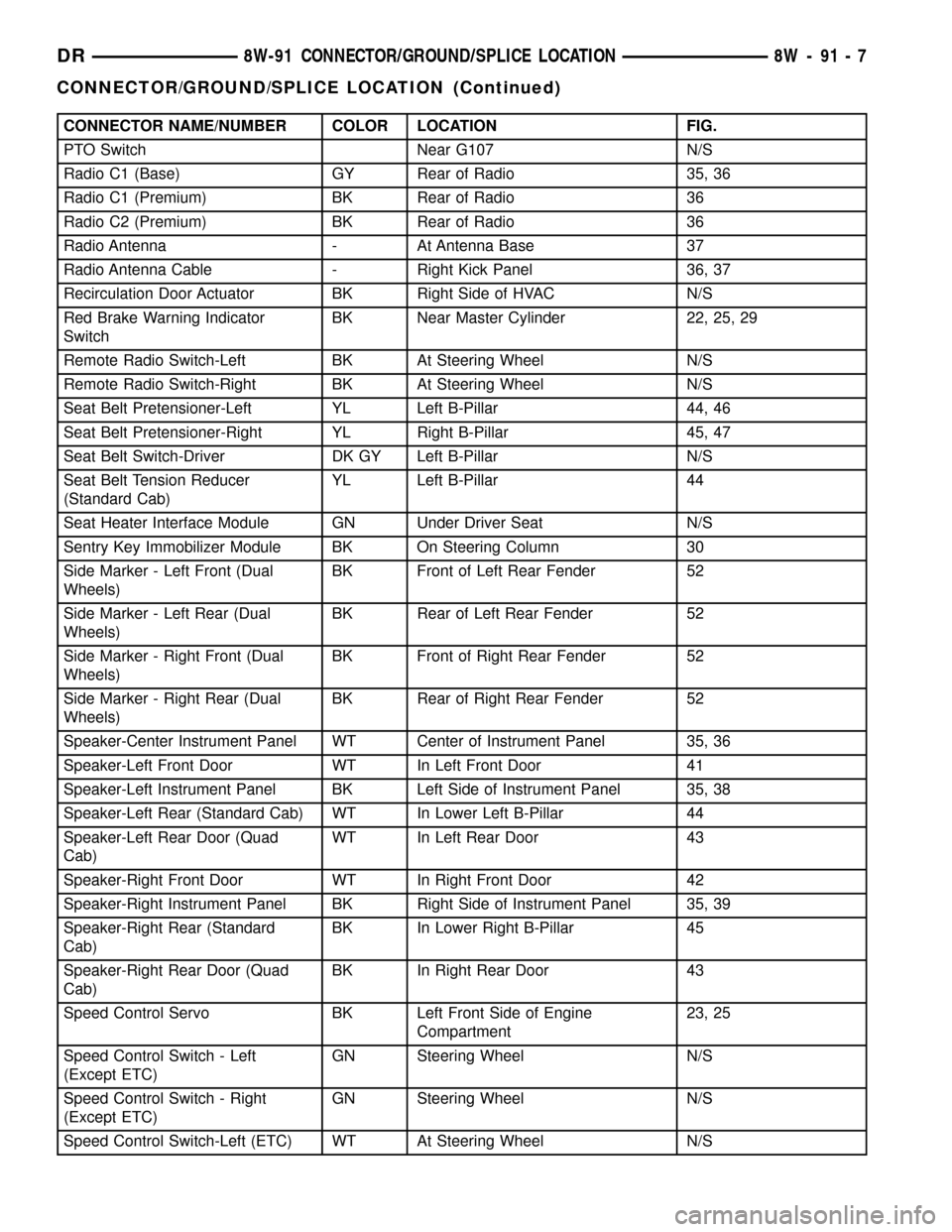
CONNECTOR NAME/NUMBER COLOR LOCATION FIG.
PTO Switch Near G107 N/S
Radio C1 (Base) GY Rear of Radio 35, 36
Radio C1 (Premium) BK Rear of Radio 36
Radio C2 (Premium) BK Rear of Radio 36
Radio Antenna - At Antenna Base 37
Radio Antenna Cable - Right Kick Panel 36, 37
Recirculation Door Actuator BK Right Side of HVAC N/S
Red Brake Warning Indicator
SwitchBK Near Master Cylinder 22, 25, 29
Remote Radio Switch-Left BK At Steering Wheel N/S
Remote Radio Switch-Right BK At Steering Wheel N/S
Seat Belt Pretensioner-Left YL Left B-Pillar 44, 46
Seat Belt Pretensioner-Right YL Right B-Pillar 45, 47
Seat Belt Switch-Driver DK GY Left B-Pillar N/S
Seat Belt Tension Reducer
(Standard Cab)YL Left B-Pillar 44
Seat Heater Interface Module GN Under Driver Seat N/S
Sentry Key Immobilizer Module BK On Steering Column 30
Side Marker - Left Front (Dual
Wheels)BK Front of Left Rear Fender 52
Side Marker - Left Rear (Dual
Wheels)BK Rear of Left Rear Fender 52
Side Marker - Right Front (Dual
Wheels)BK Front of Right Rear Fender 52
Side Marker - Right Rear (Dual
Wheels)BK Rear of Right Rear Fender 52
Speaker-Center Instrument Panel WT Center of Instrument Panel 35, 36
Speaker-Left Front Door WT In Left Front Door 41
Speaker-Left Instrument Panel BK Left Side of Instrument Panel 35, 38
Speaker-Left Rear (Standard Cab) WT In Lower Left B-Pillar 44
Speaker-Left Rear Door (Quad
Cab)WT In Left Rear Door 43
Speaker-Right Front Door WT In Right Front Door 42
Speaker-Right Instrument Panel BK Right Side of Instrument Panel 35, 39
Speaker-Right Rear (Standard
Cab)BK In Lower Right B-Pillar 45
Speaker-Right Rear Door (Quad
Cab)BK In Right Rear Door 43
Speed Control Servo BK Left Front Side of Engine
Compartment23, 25
Speed Control Switch - Left
(Except ETC)GN Steering Wheel N/S
Speed Control Switch - Right
(Except ETC)GN Steering Wheel N/S
Speed Control Switch-Left (ETC) WT At Steering Wheel N/S
DR8W-91 CONNECTOR/GROUND/SPLICE LOCATION 8W - 91 - 7
CONNECTOR/GROUND/SPLICE LOCATION (Continued)
Page 1165 of 2627

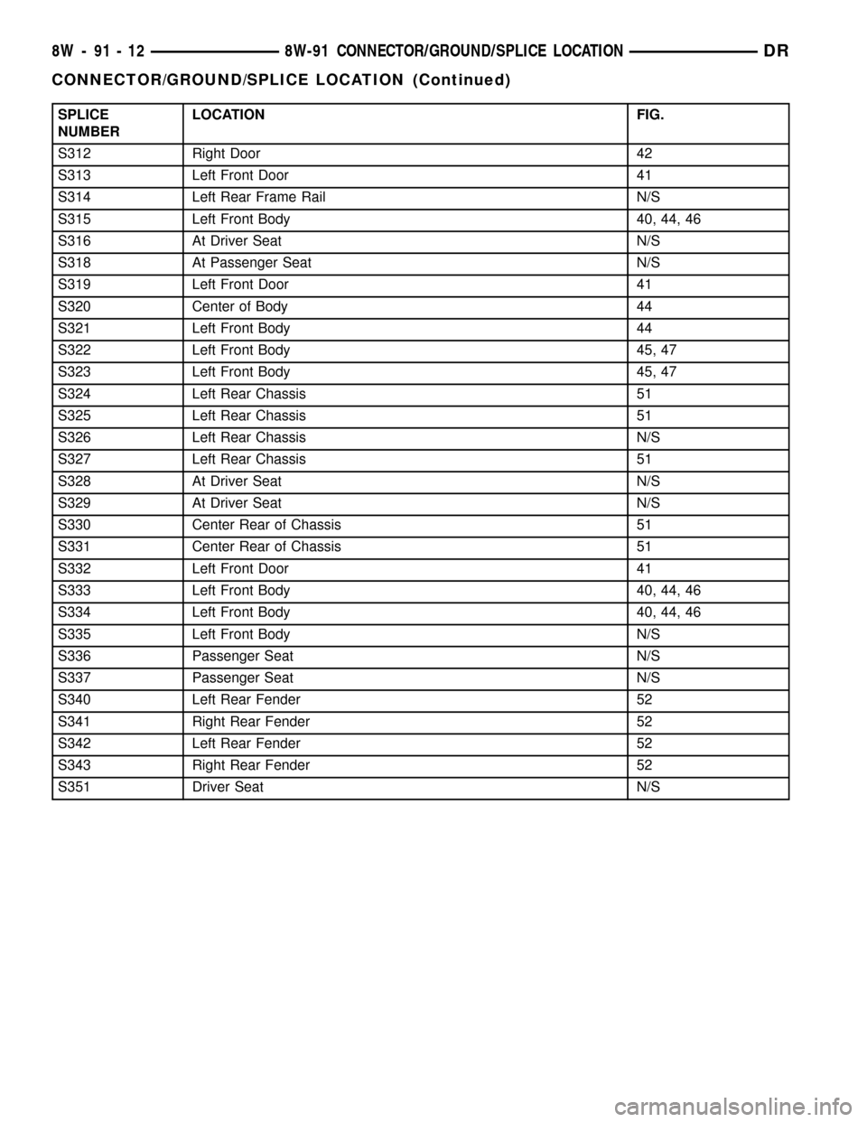
SPLICE
NUMBERLOCATION FIG.
S312 Right Door 42
S313 Left Front Door 41
S314 Left Rear Frame Rail N/S
S315 Left Front Body 40, 44, 46
S316 At Driver Seat N/S
S318 At Passenger Seat N/S
S319 Left Front Door 41
S320 Center of Body 44
S321 Left Front Body 44
S322 Left Front Body 45, 47
S323 Left Front Body 45, 47
S324 Left Rear Chassis 51
S325 Left Rear Chassis 51
S326 Left Rear Chassis N/S
S327 Left Rear Chassis 51
S328 At Driver Seat N/S
S329 At Driver Seat N/S
S330 Center Rear of Chassis 51
S331 Center Rear of Chassis 51
S332 Left Front Door 41
S333 Left Front Body 40, 44, 46
S334 Left Front Body 40, 44, 46
S335 Left Front Body N/S
S336 Passenger Seat N/S
S337 Passenger Seat N/S
S340 Left Rear Fender 52
S341 Right Rear Fender 52
S342 Left Rear Fender 52
S343 Right Rear Fender 52
S351 Driver Seat N/S
8W - 91 - 12 8W-91 CONNECTOR/GROUND/SPLICE LOCATIONDR
CONNECTOR/GROUND/SPLICE LOCATION (Continued)
Page 1638 of 2627

CAUTION: Do not attempt to remove sensor from
its mounting bracket as electronic calibration will
be destroyed (sensor-to-bracket mounting screws
are permanently attached). Two accelerator lever
set screws (Fig. 3) are used to position lever. Do
not attempt to alter positions of these set screws as
electronic calibration will be destroyed.
(1) Disconnect both negative battery cables at both
batteries.
(2) Remove cable cover (Fig. 1). Cable cover is
attached with 2 Phillips screws, 2 plastic retention
clips and 2 push tabs (Fig. 1). Remove 2 Phillips
screws and carefully pry out 2 retention clips. After
clip removal, push rearward on front tab, and
upward on lower tab for cover removal.
(3) Using finger pressure only, disconnect end of
speed control servo cable from throttle lever pin by
pulling forward on connector while holding lever
rearward (Fig. 2).DO NOT try to pull connector
off perpendicular to lever pin. Connector will
be broken.
(4) Using two small screwdrivers, pry throttle
cable connector socket from throttle lever ball (Fig.
2).Be very careful not to bend throttle lever
arm.
(5) Disconnect transmission control cable at lever
arm (if equipped). Refer to 21, Transmission.
(6) Squeeze pinch tabs on speed control cable (Fig.
2) and pull cable rearward to remove from cable
mounting bracket.
(7) Squeeze pinch tabs on throttle cable (Fig. 2)
and pull cable rearward to remove from cable mount-
ing bracket.
(8) Refer to 21, Transmission for transmission con-
trol cable removal procedures.
(9) Disconnect wiring harness clip (Fig. 3) at bot-
tom of bracket.
(10) Remove 6 mounting bolts (Fig. 3) and par-
tially remove APPS assembly from engine. After
assembly is partially removed, disconnect electrical
connector from bottom of sensor by pushing on con-
nector tab (Fig. 4).
(11) Remove APPS assembly from engine.
Battery Tray Mounted Sensor :
The APPS is serviced (replaced) as one assembly
including the sensor, plastic housing and cable. The
APPS assembly is located under the left (drivers
side) vehicle battery tray (Fig. 5). Access to APPS is
gained from over top of left / front tire.
(1) Disconnect negative battery cable at battery.
(2) Disconnect APPS cable at accelerator pedal.
Refer to Accelerator Pedal Removal / Installation.
(3) Remove wheel house liner at left / front wheel.
Refer to Body.(4) Gain access to APPS electrical connector by
opening swing-down door (Fig. 6). Disconnect electri-
cal connector.
(5) Remove 3 mounting bolts (Fig. 6).
(6) Remove APPS assembly from battery tray.
Fig. 1 CABLE/LEVER/THROTTLE LINKAGE COVER
1 - CABLE/LEVER/LINKAGE COVER
2 - PUSH UP LOWER TAB
3 - SCREWS/CLIPS (2)
4 - TAB PUSH HERE
Fig. 2 SERVO CABLE AT THROTTLE LEVER
1 - PINCH (2) TABS
2 - CABLE MOUNTING BRACKET
3 - PINCH TABS (2)
4 - OFF
5 - THROTTLE CABLE
6 - THROTTLE LEVER
7 - THROTTLE LEVER PIN
8 - OFF
9 - CONNECTOR
10 - SPEED CONTROL CABLE
DRFUEL INJECTION - DIESEL 14 - 69
ACCELERATOR PEDAL POSITION SENSOR (Continued)
Page 1666 of 2627

(8) For columns without tilt remove the bracket to
gain access to the ignition switch mounting screws.
(Fig. 10)
(9) Disconnect the electrical connector at rear of
ignition switch (Fig. 11).
(10) Remove ignition switch mounting screw.
(11) Using a small screwdriver, push on locking
tab and remove switch from steering column.
INSTALLATION
The ignition key must be in the key cylinder for
cylinder removal. The key cylinder must be removed
first before installing ignition switch.
(1) Before installing ignition switch, rotate the slot
in the switch to the ON position.(2) Connect the electrical connector to rear of the
ignition switch. Make sure that locking tabs are fully
seated into wiring connector.
(3) Position switch to column and install the
mounting screw. Tighten screw to 3 N´m (26 in. lbs.).
(4) Install the tilt lever bracket mounting screws.
Tighten screws to 4.5 N´m (40 in. lbs.).
(5) If the column is non-tilt install the bracket.
Tighten screws to 4.5 N´m (40 in. lbs.) (Fig. 10)
(6) Position the wire retainer into the tilt lever
bracket.
(7) Reconnect the lower clockspring connectors.
(8) Install the key cylinder.
(9) Install steering column upper and lower
shrouds.
(10) Enable the airbag system. (Refer to 8 - ELEC-
TRICAL/RESTRAINTS/DRIVER AIRBAG - INSTAL-
LATION).
KEY-IN IGNITION SWITCH
DESCRIPTION
The key-in ignition switch is integral to the igni-
tion switch, which is mounted on the left side of the
steering column. It closes a path to ground for the
Central Timer Module (CTM) when the ignition key
is inserted in the ignition key cylinder and the driver
door ajar switch is closed (driver door is open). The
key-in ignition switch opens the ground path when
the key is removed from the ignition key cylinder.
The ground path is also opened when the driver door
ajar switch is open (driver door is closed).
The key-in ignition switch cannot be repaired and,
if faulty or damaged, the entire ignition switch must
be replaced, (Refer to 19 - STEERING/COLUMN/IG-
NITION SWITCH - REMOVAL).
DIAGNOSIS AND TESTING - IGNITION SWITCH
AND KEY LOCK CYLINDER
ELECTRICAL DIAGNOSIS
For ignition switch electrical schematics, refer to
Ignition Switch in the appropriate section of Electri-
cal Wiring Diagrams.
MECHANICAL DIAGNOSIS (KEY DIFFICULT TO
ROTATE)
(Refer to 19 - STEERING/COLUMN/IGNITION
SWITCH - DIAGNOSIS AND TESTING).
Fig. 10 IGNITION SWITCH WITHOUT TILT
1 - Ignition Switch Mounting Screws
2 - Non-Tilt Mounitng Bracket Screws
Fig. 11 IGNITION SWITCH
1 - Ignition Switch
2 - Ignition Switch Mounting Screws
DRCOLUMN 19 - 11
IGNITION SWITCH (Continued)
Page 2352 of 2627

(2) Position the switch bezel and seat the attach-
ment clips fully.
(3) Seat the clips on the steering column opening
cover and the lower drivers side bezel fully.
INSTRUMENT PANEL CENTER
BEZEL
REMOVAL
WARNING: ON VEHICLES EQUIPPED WITH AIR-
BAGS, DISABLE THE AIRBAG SYSTEM BEFORE
ATTEMPTING ANY STEERING WHEEL, STEERING
COLUMN, SEAT BELT TENSIONER, OR INSTRU-
MENT PANEL COMPONENT DIAGNOSIS OR SER-
VICE. DISCONNECT AND ISOLATE THE BATTERY
NEGATIVE (GROUND) CABLE, THEN WAIT TWO
MINUTES FOR THE AIRBAG SYSTEM CAPACITOR
TO DISCHARGE BEFORE PERFORMING FURTHER
DIAGNOSIS OR SERVICE. THIS IS THE ONLY SURE
WAY TO DISABLE THE AIRBAG SYSTEM. FAILURE
TO TAKE THE PROPER PRECAUTIONS COULD
RESULT IN ACCIDENTAL AIRBAG DEPLOYMENT
AND POSSIBLE PERSONAL INJURY.
CAUTION: When removing and installing the center
bezel, use tape or other suitable material to protect
the cupholder and ash receiver from damage.
(1) Disconnect and isolate the negative battery
cable.
(2) Remove the steering column opening cover.
(Refer to 23 - BODY/INSTRUMENT PANEL/STEER-
ING COLUMN OPENING COVER - REMOVAL)
(3) Open the ashtray and cup holder.
(4) Remove the one center bezel retaining screw
(Fig. 18).
CAUTION: Extreme care must be taken not to
scratch the ashtray door while removing the instru-
ment panel center bezel. Apply masking tape to the
ashtray door if the center bezel is not being com-
pletely removed from the instrument panel.
(5) Using a trim stick C-4755 or equivalent, gently
pry the center bezel free from the instrument panel.
(6) Working behind the center bezel, disconnect all
electrical connectors and remove the bezel.
INSTALLATION
WARNING: ON VEHICLES EQUIPPED WITH AIR-
BAGS, DISABLE THE AIRBAG SYSTEM BEFORE
ATTEMPTING ANY STEERING WHEEL, STEERING
COLUMN, SEAT BELT TENSIONER, OR INSTRU-
MENT PANEL COMPONENT DIAGNOSIS OR SER-
VICE. DISCONNECT AND ISOLATE THE BATTERY
NEGATIVE (GROUND) CABLE, THEN WAIT TWO
MINUTES FOR THE AIRBAG SYSTEM CAPACITOR
TO DISCHARGE BEFORE PERFORMING FURTHER
DIAGNOSIS OR SERVICE. THIS IS THE ONLY SURE
WAY TO DISABLE THE AIRBAG SYSTEM. FAILURE
TO TAKE THE PROPER PRECAUTIONS COULD
RESULT IN ACCIDENTAL AIRBAG DEPLOYMENT
AND POSSIBLE PERSONAL INJURY.
CAUTION: When removing and installing the center
bezel, use tape or other suitable material to protect
the cupholder and ash receiver from damage.
(1) Working behind the center bezel, connect all
electrical connectors.
(2) Gently install the center bezel on the instru-
ment panel by pushing straight in and seat the
attachment clips fully.
(3) Install the one center bezel screw.
(4) Install the steering column opening cover.
(Refer to 23 - BODY/INSTRUMENT PANEL/STEER-
ING COLUMN OPENING COVER - INSTALLA-
TION)
(5) Connect the negative battery cable.
Fig. 18 CENTER BEZEL
1 - INSTRUMENT PANEL
2 - CENTER BEZEL
3 - SCREW
DRINSTRUMENT PANEL 23 - 57
INSTRUMENT PANEL HEADLAMP SWITCH BEZEL (Continued)
Page 2489 of 2627

ber above the heating, ventilation and air condition-
ing (HVAC) housing. On models equipped with air
conditioning, the air passes through the evaporator
coil. Air flow can be directed either through or
around the heater core. This is done by adjusting the
blend door with the temperature control knob on the
A/C-heater control located the instrument panel. The
air flow can then be directed from the panel, floor
and defrost outlets in various combinations using the
mode control knob located on the A/C-heater control.
Air flow velocity can be adjusted with the blower
speed selector located on the A/C-heater control.
NOTE: It is important to keep the air intake opening
clear of debris. Leaf particles and other debris that
is small enough to pass through the cowl opening
screen can accumulate within the HVAC housing.
The closed, warm, damp and dark environment cre-
ated within the housing is ideal for the growth of
certain molds, mildews and other fungi. Any accu-mulation of decaying plant matter provides an addi-
tional food source for fungal spores, which enter
the housing with the fresh intake-air. Excess debris,
as well as objectionable odors created by decaying
plant matter and growing fungi can be discharged
into the passenger compartment during heater-A/C
operation if the air intake opening is not kept clear
of debris.
The heater and air conditioning systems are blend-
air type systems. In a blend-air system, a blend door
controls the amount of unconditioned air (or cooled
air from the evaporator on models with air condition-
ing) that is allowed to flow through, or around, the
heater core. A temperature control knob determines
the discharge air temperature by actuating an elec-
tric motor, which operates the blend door. This allows
an almost immediate control of the output air tem-
perature of the system.
On all models, the outside air intake can be shut
off by selecting the Recirculation Mode with the
mode control knob. This will operate a electric actu-
ated recirculation air door that closes off the outside
fresh air intake and recirculates the air that is
already inside the vehicle.
The air conditioning compressor can be engaged in
any mode by pressing the snowflake, A/C on/off but-
ton. It can also be engaged by placing the mode con-
trol in the mix to defrost positions. This will remove
heat and humidity from the air before it is directed
through or around the heater core. The mode control
knob on the A/C-heater control is used to also direct
the conditioned air to the selected system outlets.
The mode control switch uses an electric motor to
control the mode doors.
The defroster outlet receives airflow from the
HVAC housing through the molded plastic defroster
duct, which connects to the HVAC housing defroster
outlet. The airflow from the defroster outlets is
directed by fixed vanes in the defroster outlet grilles
and cannot be adjusted. The defroster outlet grilles
are integral to the instrument panel top cover.
The side window demister outlets receive airflow
from the HVAC housing through the molded plastic
defroster duct and two molded plastic demister ducts.
The airflow from the side window demister outlets is
directed by fixed vanes in the demister outlet grilles
and cannot be adjusted. The side window demister
outlet grilles are integral to the instrument panel.
The demisters direct air from the HVAC housing
through the outlets located on the top corners of the
instrument panel. The demisters operate when the
mode control knob is positioned in the floor-defrost
and defrost-only settings. Some air may be noticeable
from the demister outlets when the mode control is
in the bi-level to floor positions.
Fig. 1 HVAC Housing - Dual Zone Shown, Single
Zone Typical
1 - NUT
2 - PASSENGER BLEND DOOR ACTUATOR
3 - NUT
4 - INLET BAFFLE
5 - RECIRCULATION DOOR ACTUATOR
6 - RECIRCULATION DOOR
7 - DRIVER SIDE BLEND DOOR ACTUATOR
8 - HVAC HOUSING
9 - BOLT
10 - DEFROSTER DOOR ACTUATOR
11 - MODE DOOR ACTUATOR
24 - 2 HEATING & AIR CONDITIONINGDR
HEATING & AIR CONDITIONING (Continued)