1998 DODGE RAM 1500 seats
[x] Cancel search: seatsPage 1423 of 2627
þ Loss of engine power
þ Engine misfiring
þ Poor fuel economy
²Possible indications of the cylinder head gasket
leaking between a cylinder and an adjacent water
jacket are:
þ Engine overheating
þ Loss of coolant
þ Excessive steam (white smoke) emitting from
exhaust
þ Coolant foaming
CYLINDER-TO-CYLINDER LEAKAGE TEST
To determine if an engine cylinder head gasket is
leaking between adjacent cylinders, follow the proce-
dures in Cylinder Compression Pressure Test in this
section. An engine cylinder head gasket leaking
between adjacent cylinders will result in approxi-
mately a 50±70% reduction in compression pressure.
CYLINDER-TO-WATER JACKET LEAKAGE TEST
WARNING: USE EXTREME CAUTION WHEN THE
ENGINE IS OPERATING WITH COOLANT PRES-
SURE CAP REMOVED.
VISUAL TEST METHOD
With the engine cool, remove the coolant pressure
cap. Start the engine and allow it to warm up until
thermostat opens.
If a large combustion/compression pressure leak
exists, bubbles will be visible in the coolant.
COOLING SYSTEM TESTER METHOD
WARNING: WITH COOLING SYSTEM TESTER IN
PLACE, PRESSURE WILL BUILD UP FAST. EXCES-
SIVE PRESSURE BUILT UP, BY CONTINUOUS
ENGINE OPERATION, MUST BE RELEASED TO A
SAFE PRESSURE POINT. NEVER PERMIT PRES-
SURE TO EXCEED 138 kPa (20 psi).
Install Cooling System Tester 7700 or equivalent to
pressure cap neck. Start the engine and observe the
tester's pressure gauge. If gauge pulsates with every
power stroke of a cylinder a combustion pressure
leak is evident.
CHEMICAL TEST METHOD
Combustion leaks into the cooling system can also
be checked by using Bloc-Chek Kit C-3685-A or
equivalent. Perform test following the procedures
supplied with the tool kit.
REMOVAL
(1) Disconnect the battery negative cable.
(2) Drain cooling system.
(3) Remove the air cleaner resonator and duct
work.
(4) Remove the generator.
(5) Remove closed crankcase ventilation system.
(6) Disconnect the evaporation control system.
(7) Perform the Fuel System Pressure Release pro-
cedure (Refer to 14 - FUEL SYSTEM/FUEL DELIV-
ERY - STANDARD PROCEDURE). Disconnect the
fuel supply line (Refer to 14 - FUEL SYSTEM/FUEL
DELIVERY/QUICK CONNECT FITTING - STAN-
DARD PROCEDURE).
(8) Disconnect heater hoses.
(9) Remove cylinder head covers and gaskets.
(10) Remove intake manifold and throttle body as
an assembly.
(11) Remove rocker arm assemblies and push rods.
Identify to ensure installation in original locations.
(12) Remove the head bolts from each cylinder
head and remove cylinder heads. Discard the cylin-
der head gasket.
CLEANING
Clean all surfaces of cylinder block and cylinder
heads.
Clean cylinder block front and rear gasket surfaces
using a suitable solvent.
INSPECTION
(1) Inspect the cylinder head for out-of-flatness,
using a straightedge and a feeler gauge. If tolerances
exceed 0.0508 mm (0.002 in.) replace the cylinder
head.
(2) Inspect the valve seats for damage. Service the
valve seats as necessary.
(3) Inspect the valve guides for wear, cracks or
looseness. If either condition exist, replace the cylin-
der head.
(4) Inspect pushrods. Replace worn or bent push-
rods.
INSTALLATION
(1) Clean all surfaces of cylinder block and cylin-
der heads.
(2) Clean cylinder block front and rear gasket sur-
faces using a suitable solvent.
CAUTION: The head gaskets are not interchange-
able between left and right sides. They are marked
ªLº and ªRº to indicate left and right sides.
(3) Position new cylinder head gaskets onto the
cylinder block.
9 - 200 ENGINE - 5.7LDR
CYLINDER HEAD (Continued)
Page 1425 of 2627
INTAKE/EXHAUST VALVES &
SEATS
DESCRIPTION
DESCRIPTION - VALVE GUIDES
The valve guides are made of powered metal and
are pressed into the cylinder head. The guides are
not replaceable or serviceable, and valve guide ream-
ing is not recommended. If the guides are worn
beyond acceptable limits, replace the cylinder heads.
DESCRIPTION
Both the intake and exhaust valves are made of
steel. The intake valve is 50.93 mm (2.00 inches) in
diameter and the exhaust valve is 39.53 mm (1.55
inches) in diameter. All valves use three bead lock
keepers to retain the springs and promote valve rota-
tion.
STANDARD PROCEDURE - REFACING
NOTE: Valve seats that are worn or burned can be
reworked, provided that correct angle and seat
width are maintained. Otherwise the cylinder head
must be replaced.
NOTE: When refacing valves and valve seats, it is
important that the correct size valve guide pilot be
used for reseating stones. A true and complete sur-
face must be obtained.
(1) Using a suitable dial indicator measure the
center of the valve seat Total run out must not
exceed 0.051 mm (0.002 in).
(2) Apply a small amount of Prussian blue to the
valve seat, insert the valve into the cylinder head,
while applying light pressure on the valve rotate the
valve. Remove the valve and examine the valve face.
If the blue is transferred below the top edge of the
valve face, lower the valve seat using a 15 degree
stone. If the blue is transferred to the bottom edge of
the valve face, raise the valve seat using a 65 degree
stone.
(3) When the seat is properly positioned the width
of the intake seat must be 1.018 - 1.62 mm (0.0464 -
0.0637 in.) and the exhaust seat must be 1.48 - 1.92
mm (0.058 - 0.075 in.).
(4) Check the valve spring installed height after
refacing the valve and seat. The installed height for
both intake and exhaust valve springs must not
exceed 46.0 mm (1.81 in.).
VALVE FACE AND VALVE SEAT ANGLE CHART
DESCRIPTION SPECIFICATION
SEAT WIDTH
INTAKE 1.018 - 1.62 mm
(0.0464 - 0.0637 in.)
EXHAUST 1.48 - 1.92 mm
(0.058 - 0.075 in.)
FACE ANGLE
(INT. AND EXT.) 45É - 45
1¤2É
SEAT ANGLE
(INT. AND EXT.) 44
1¤2É - 45É
(5)
The valve seat must maintain an angle of 44.5 ±
45.0 degrees angle.
(6) The valve face must maintain a face angle of
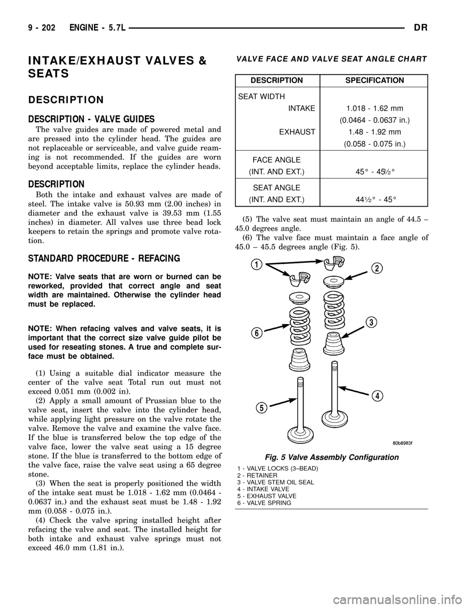
45.0 ± 45.5 degrees angle (Fig. 5).
Fig. 5 Valve Assembly Configuration
1 - VALVE LOCKS (3±BEAD)
2 - RETAINER
3 - VALVE STEM OIL SEAL
4 - INTAKE VALVE
5 - EXHAUST VALVE
6 - VALVE SPRING
9 - 202 ENGINE - 5.7LDR
Page 1426 of 2627
REMOVAL
(1) Remove the cylinder head (Refer to 9 -
ENGINE/CYLINDER HEAD - REMOVAL).
(2) Compress valve springs using Valve Spring
Compressor Tool special tool # C-3422and adapter
8464.
(3) Remove valve retaining locks, valve spring
retainers, valve stem seals and valve springs.
(4) Before removing valves, remove any burrs from
valve stem lock grooves to prevent damage to the
valve guides. Identify valves to ensure installation in
original location.
INSTALLATION
(1) Clean valves thoroughly. Discard burned,
warped and cracked valves.
(2) Remove carbon and varnish deposits from
inside of valve guides with a reliable guide cleaner.
(3) Measure valve stems for wear. If wear exceeds
0.051 mm (0.002 inch), replace the valve.
(4) Coat valve stems with lubrication oil and insert
them in cylinder head.
(5) If valves or seats are reground, check valve
stem height. If valve is too long, replace cylinder
head.
(6) Install new seals on all valve guides. Install
valve springs and valve retainers.
(7) Compress valve springs with Valve Spring
Compressor Tool special tool # C- 3422and adapter
8464, install locks and release tool. If valves and/or
seats are ground, measure the installed height of
springs. Make sure the measurement is taken from
bottom of spring seat in cylinder head to the bottom
surface of spring retainer.
(8) Install cylinder head (Refer to 9 - ENGINE/
CYLINDER HEAD - INSTALLATION).
ROCKER ARM / ADJUSTER
ASSY
REMOVAL
(1) Remove cylinder head cover.(Refer to 9 -
ENGINE/CYLINDER HEAD/CYLINDER HEAD
COVER(S) - REMOVAL)
(2) Loosen the rocker shafts using the following
sequence:Center, center-left, center-right, left,
right,.
CAUTION: The rocker shaft assemblies are not
interchangeable between intake and exhaust. The
intake rocker arms are marked with an ªIº.
(3) Remove the rocker shafts. Note location for
reassembly.CAUTION: The longer push rods are for the exhaust
side, and the shorter push rods are for intake side.
(4) Remove the pushrods. Note pushrod location
for reassembly.
INSTALLATION
CAUTION: The longer push rods are for the exhaust
side, and the shorter push rods are for intake side.
(1) Install the push rods in the same order as
removed.
CAUTION: Verify that pushrod is installed into
rocker arm and lifter correctly while installing
rocker shaft assembly. Recheck after rocker shaft
has been torqued to specification.
CAUTION: The rocker shaft assemblies are not
interchangeable between intake and exhaust. The
intake rocker arms are marked with the letter ªIº.
(2) Install rocker shaft assemblies in the same
order as removed.
CAUTION: Ensure that hold downs and rocker arms
are not overlapped when torquing bolts.
(3) Tighten the rocker shaft bolts to 22 N´m (195
in. lbs.) torque,using the following sequence:Center,
center-right, center-left, right, left.
CAUTION: DO NOT rotate or crank the engine dur-
ing or immediately after rocker arm installation.
Allow the hydraulic roller tappets adequate time to
bleed down (about 5 minutes).
(4) Install cylinder head cover (Refer to 9 -
ENGINE/CYLINDER HEAD/CYLINDER HEAD
COVER(S) - INSTALLATION).
VALVE STEM SEALS
DESCRIPTION
The valve guide seals are made of rubber and
incorporate an integral steel valve spring seat. The
integral garter spring maintains consistent lubrica-
tion control to the valve stems.
DRENGINE - 5.7L 9 - 203
INTAKE/EXHAUST VALVES & SEATS (Continued)
Page 1432 of 2627
CRANKSHAFT OIL SEAL -
REAR
DIAGNOSIS AND TESTING - REAR SEAL AREA
LEAKS
Since it is sometimes difficult to determine the
source of an oil leak in the rear seal area of the
engine, a more involved inspection is necessary. The
following steps should be followed to help pinpoint
the source of the leak.
If the leakage occurs at the crankshaft rear oil seal
area:
(1) Disconnect the battery.
(2) Raise the vehicle.
(3) Remove torque converter or clutch housing
cover and inspect rear of block for evidence of oil.
Use a black light to check for the oil leak:
(a) Circular spray pattern generally indicates
seal leakage or crankshaft damage.
(b) Where leakage tends to run straight down,
possible causes are a porous block, camshaft bore
cup plugs, oil galley pipe plugs, oil filter runoff,
and main bearing cap to cylinder block mating sur-
faces. See Engine, for proper repair procedures of
these items.
(4) If no leaks are detected, pressurized the crank-
case as outlined in the section, Inspection (Engine oil
Leaks in general)
CAUTION: Do not exceed 20.6 kPa (3 psi).
(5) If the leak is not detected, very slowly turn the
crankshaft and watch for leakage. If a leak is
detected between the crankshaft and seal while
slowly turning the crankshaft, it is possible the
crankshaft seal surface is damaged. The seal area on
the crankshaft could have minor nicks or scratches
that can be polished out with emery cloth.
CAUTION: Use extreme caution when crankshaft
polishing is necessary to remove minor nicks or
scratches. The crankshaft seal flange is specially
machined to complement the function of the rear oil
seal.
(6) For bubbles that remain steady with shaft
rotation, no further inspection can be done until dis-
assembled. (Refer to 9 - ENGINE - DIAGNOSIS AND
TESTING), under the Oil Leak row, for components
inspections on possible causes and corrections.
(7) After the oil leak root cause and appropriate
corrective action have been identified, (Refer to 9 -
ENGINE/ENGINE BLOCK/CRANKSHAFT OIL
SEAL - REAR - REMOVAL).
REMOVAL
NOTE: This procedure can be performed in vehicle.
(1) If being preformed in vehicle, remove the
transmission.
(2) Remove the flexplate (Refer to 9 - ENGINE/
ENGINE BLOCK/FLEX PLATE - REMOVAL).
NOTE: The crankshaft oil seal CAN NOT be reused
after removal.
NOTE: The crankshaft rear oil seal remover Special
Tool 8506 must be installed deeply into the seal.
Continue to tighten the removal tool into the seal
until the tool can not be turned farther. Failure to
install tool correctly the first time will cause tool to
pull free of seal without removing seal from engine.
(3) Using Special Tool 8506, remove the crankshaft
rear oil seal.
INSTALLATION
CAUTION: The rear seal must be installed dry for
proper operation. Do not lubricate the seal lip or
outer edge.
(1) Position the plastic seal guide onto the crank-
shaft rear face. Then position the crankshaft rear oil
seal onto the guide.
(2) Using Special Tools 8349 Crankshaft Rear Oil
Seal Installer and C-4171 Driver Handle, with a
hammer, tap the seal into place. Continue to tap on
the driver handle until the seal installer seats
against the cylinder block crankshaft bore.
(3) Install the flexplate.
(4) Install the transmission.
CRANKSHAFT REAR OIL SEAL
RETAINER
REMOVAL
(1) Disconnect negative cable from battery.
(2) Remove the transmission.
(3) Remove the drive plate / flywheel.
(4) Remove the oil pan (Refer to 9 - ENGINE/LU-
BRICATION/OIL PAN - REMOVAL).
(5) Remove the rear oil seal retainer mounting
bolts.
(6) Carefully remove the retainer from the engine
block.
DRENGINE - 5.7L 9 - 209
Page 1453 of 2627
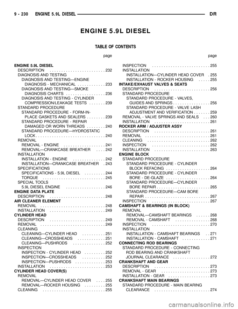
ENGINE 5.9L DIESEL
TABLE OF CONTENTS
page page
ENGINE 5.9L DIESEL
DESCRIPTION........................232
DIAGNOSIS AND TESTING
DIAGNOSIS AND TESTINGÐENGINE
DIAGNOSIS - MECHANICAL............233
DIAGNOSIS AND TESTINGÐSMOKE
DIAGNOSIS CHARTS.................236
DIAGNOSIS AND TESTING - CYLINDER
COMPRESSION/LEAKAGE TESTS.......239
STANDARD PROCEDURE
STANDARD PROCEDURE - FORM-IN-
PLACE GASKETS AND SEALERS........239
STANDARD PROCEDURE - REPAIR
DAMAGED OR WORN THREADS........240
STANDARD PROCEDUREÐHYDROSTATIC
LOCK..............................240
REMOVAL
REMOVAL - ENGINE..................241
REMOVALÐCRANKCASE BREATHER....242
INSTALLATION
INSTALLATION - ENGINE..............242
INSTALLATIONÐCRANKCASE BREATHER . 243
SPECIFICATIONS
SPECIFICATIONS - 5.9L DIESEL.........244
TORQUE...........................245
SPECIAL TOOLS
5.9L DIESEL ENGINE.................246
ENGINE DATA PLATE
DESCRIPTION........................248
AIR CLEANER ELEMENT
REMOVAL............................248
INSTALLATION........................249
CYLINDER HEAD
DESCRIPTION........................249
REMOVAL............................249
CLEANING
CLEANINGÐCYLINDER HEAD..........251
CLEANINGÐCROSSHEADS............251
CLEANINGÐPUSHRODS..............252
INSPECTION
INSPECTION - CYLINDER HEAD.........252
INSPECTIONÐCROSSHEADS..........252
INSPECTIONÐPUSHRODS.............253
INSTALLATION........................253
CYLINDER HEAD COVER(S)
REMOVAL
REMOVALÐCYLINDER HEAD COVER....255
REMOVALÐROCKER HOUSING.........255
CLEANING...........................255INSPECTION.........................255
INSTALLATION
INSTALLATIONÐCYLINDER HEAD COVER . 255
INSTALLATION - ROCKER HOUSING.....255
INTAKE/EXHAUST VALVES & SEATS
DESCRIPTION........................256
STANDARD PROCEDURE
STANDARD PROCEDURE - VALVES,
GUIDES AND SPRINGS................256
STANDARD PROCEDURE - VALVE LASH
ADJUSTMENT AND VERIFICATION.......259
REMOVAL - VALVE SPRINGS AND SEALS . . . 260
INSTALLATION........................261
ROCKER ARM / ADJUSTER ASSY
DESCRIPTION........................261
REMOVAL............................261
CLEANING...........................262
INSPECTION.........................262
INSTALLATION........................263
ENGINE BLOCK
STANDARD PROCEDURE
STANDARD PROCEDURE - CYLINDER
BLOCK REFACING...................264
STANDARD PROCEDURE - CYLINDER
BORE - DE-GLAZE...................264
STANDARD PROCEDUREÐCYLINDER
BORE REPAIR.......................265
STANDARD PROCEDUREÐCAM BORE
REPAIR ............................267
INSPECTION.........................267
CAMSHAFT & BEARINGS (IN BLOCK)
REMOVAL
REMOVALÐCAMSHAFT BEARINGS......268
REMOVAL - CAMSHAFT...............268
INSPECTION.........................270
INSTALLATION
INSTALLATION - CAMSHAFT BEARINGS . . 271
INSTALLATION - CAMSHAFT............271
CONNECTING ROD BEARINGS
STANDARD PROCEDURE - CONNECTING
ROD BEARING AND CRANKSHAFT
JOURNAL CLEARANCE................272
CRANKSHAFT AND GEAR
DESCRIPTION........................273
REMOVAL - GEAR.....................273
INSTALLATION - GEAR..................273
CRANKSHAFT MAIN BEARINGS
STANDARD PROCEDURE - MAIN BEARING
CLEARANCE........................274
9 - 230 ENGINE 5.9L DIESELDR
Page 1460 of 2627
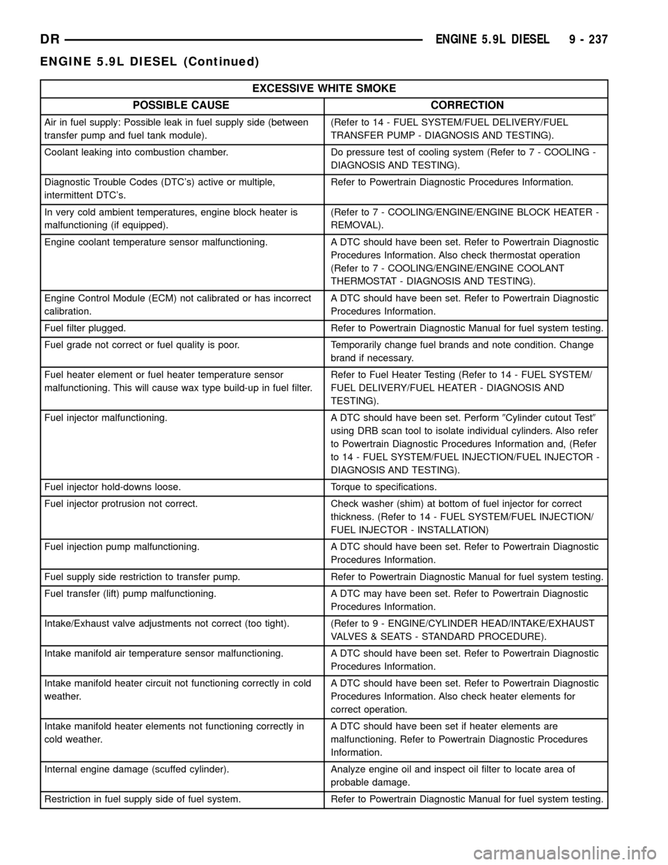
EXCESSIVE WHITE SMOKE
POSSIBLE CAUSE CORRECTION
Air in fuel supply: Possible leak in fuel supply side (between
transfer pump and fuel tank module).(Refer to 14 - FUEL SYSTEM/FUEL DELIVERY/FUEL
TRANSFER PUMP - DIAGNOSIS AND TESTING).
Coolant leaking into combustion chamber. Do pressure test of cooling system (Refer to 7 - COOLING -
DIAGNOSIS AND TESTING).
Diagnostic Trouble Codes (DTC's) active or multiple,
intermittent DTC's.Refer to Powertrain Diagnostic Procedures Information.
In very cold ambient temperatures, engine block heater is
malfunctioning (if equipped).(Refer to 7 - COOLING/ENGINE/ENGINE BLOCK HEATER -
REMOVAL).
Engine coolant temperature sensor malfunctioning. A DTC should have been set. Refer to Powertrain Diagnostic
Procedures Information. Also check thermostat operation
(Refer to 7 - COOLING/ENGINE/ENGINE COOLANT
THERMOSTAT - DIAGNOSIS AND TESTING).
Engine Control Module (ECM) not calibrated or has incorrect
calibration.A DTC should have been set. Refer to Powertrain Diagnostic
Procedures Information.
Fuel filter plugged. Refer to Powertrain Diagnostic Manual for fuel system testing.
Fuel grade not correct or fuel quality is poor. Temporarily change fuel brands and note condition. Change
brand if necessary.
Fuel heater element or fuel heater temperature sensor
malfunctioning. This will cause wax type build-up in fuel filter.Refer to Fuel Heater Testing (Refer to 14 - FUEL SYSTEM/
FUEL DELIVERY/FUEL HEATER - DIAGNOSIS AND
TESTING).
Fuel injector malfunctioning. A DTC should have been set. Perform9Cylinder cutout Test9
using DRB scan tool to isolate individual cylinders. Also refer
to Powertrain Diagnostic Procedures Information and, (Refer
to 14 - FUEL SYSTEM/FUEL INJECTION/FUEL INJECTOR -
DIAGNOSIS AND TESTING).
Fuel injector hold-downs loose. Torque to specifications.
Fuel injector protrusion not correct. Check washer (shim) at bottom of fuel injector for correct
thickness. (Refer to 14 - FUEL SYSTEM/FUEL INJECTION/
FUEL INJECTOR - INSTALLATION)
Fuel injection pump malfunctioning. A DTC should have been set. Refer to Powertrain Diagnostic
Procedures Information.
Fuel supply side restriction to transfer pump. Refer to Powertrain Diagnostic Manual for fuel system testing.
Fuel transfer (lift) pump malfunctioning. A DTC may have been set. Refer to Powertrain Diagnostic
Procedures Information.
Intake/Exhaust valve adjustments not correct (too tight). (Refer to 9 - ENGINE/CYLINDER HEAD/INTAKE/EXHAUST
VALVES & SEATS - STANDARD PROCEDURE).
Intake manifold air temperature sensor malfunctioning. A DTC should have been set. Refer to Powertrain Diagnostic
Procedures Information.
Intake manifold heater circuit not functioning correctly in cold
weather.A DTC should have been set. Refer to Powertrain Diagnostic
Procedures Information. Also check heater elements for
correct operation.
Intake manifold heater elements not functioning correctly in
cold weather.A DTC should have been set if heater elements are
malfunctioning. Refer to Powertrain Diagnostic Procedures
Information.
Internal engine damage (scuffed cylinder). Analyze engine oil and inspect oil filter to locate area of
probable damage.
Restriction in fuel supply side of fuel system. Refer to Powertrain Diagnostic Manual for fuel system testing.
DRENGINE 5.9L DIESEL 9 - 237
ENGINE 5.9L DIESEL (Continued)
Page 1461 of 2627
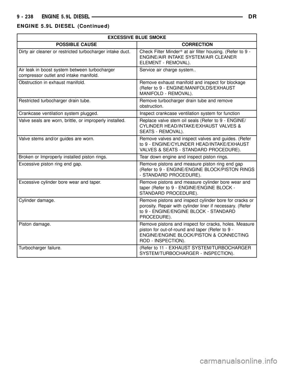
EXCESSIVE BLUE SMOKE
POSSIBLE CAUSE CORRECTION
Dirty air cleaner or restricted turbocharger intake duct. Check Filter MinderTat air filter housing. (Refer to 9 -
ENGINE/AIR INTAKE SYSTEM/AIR CLEANER
ELEMENT - REMOVAL).
Air leak in boost system between turbocharger
compressor outlet and intake manifold.Service air charge system..
Obstruction in exhaust manifold. Remove exhaust manifold and inspect for blockage
(Refer to 9 - ENGINE/MANIFOLDS/EXHAUST
MANIFOLD - REMOVAL).
Restricted turbocharger drain tube. Remove turbocharger drain tube and remove
obstruction.
Crankcase ventilation system plugged. Inspect crankcase ventilation system for function
Valve seals are worn, brittle, or improperly installed. Replace valve stem oil seals (Refer to 9 - ENGINE/
CYLINDER HEAD/INTAKE/EXHAUST VALVES &
SEATS - REMOVAL).
Valve stems and/or guides are worn. Remove valves and inspect valves and guides. (Refer
to 9 - ENGINE/CYLINDER HEAD/INTAKE/EXHAUST
VALVES & SEATS - STANDARD PROCEDURE).
Broken or Improperly installed piston rings. Tear down engine and inspect piston rings.
Excessive piston ring end gap. Remove pistons and measure piston ring end gap
(Refer to 9 - ENGINE/ENGINE BLOCK/PISTON RINGS
- STANDARD PROCEDURE).
Excessive cylinder bore wear and taper. Remove pistons and measure cylinder bore wear and
taper (Refer to 9 - ENGINE/ENGINE BLOCK -
STANDARD PROCEDURE).
Cylinder damage. Remove pistons and inspect cylinder bore for cracks or
porosity. Repair with cylinder liner if necessary. (Refer
to 9 - ENGINE/ENGINE BLOCK - STANDARD
PROCEDURE).
Piston damage. Remove pistons and inspect for cracks, holes. Measure
piston for out-of-round and taper (Refer to 9 -
ENGINE/ENGINE BLOCK/PISTON & CONNECTING
ROD - INSPECTION).
Turbocharger failure. (Refer to 11 - EXHAUST SYSTEM/TURBOCHARGER
SYSTEM/TURBOCHARGER - INSPECTION).
9 - 238 ENGINE 5.9L DIESELDR
ENGINE 5.9L DIESEL (Continued)
Page 1476 of 2627
INSPECTIONÐPUSHRODS
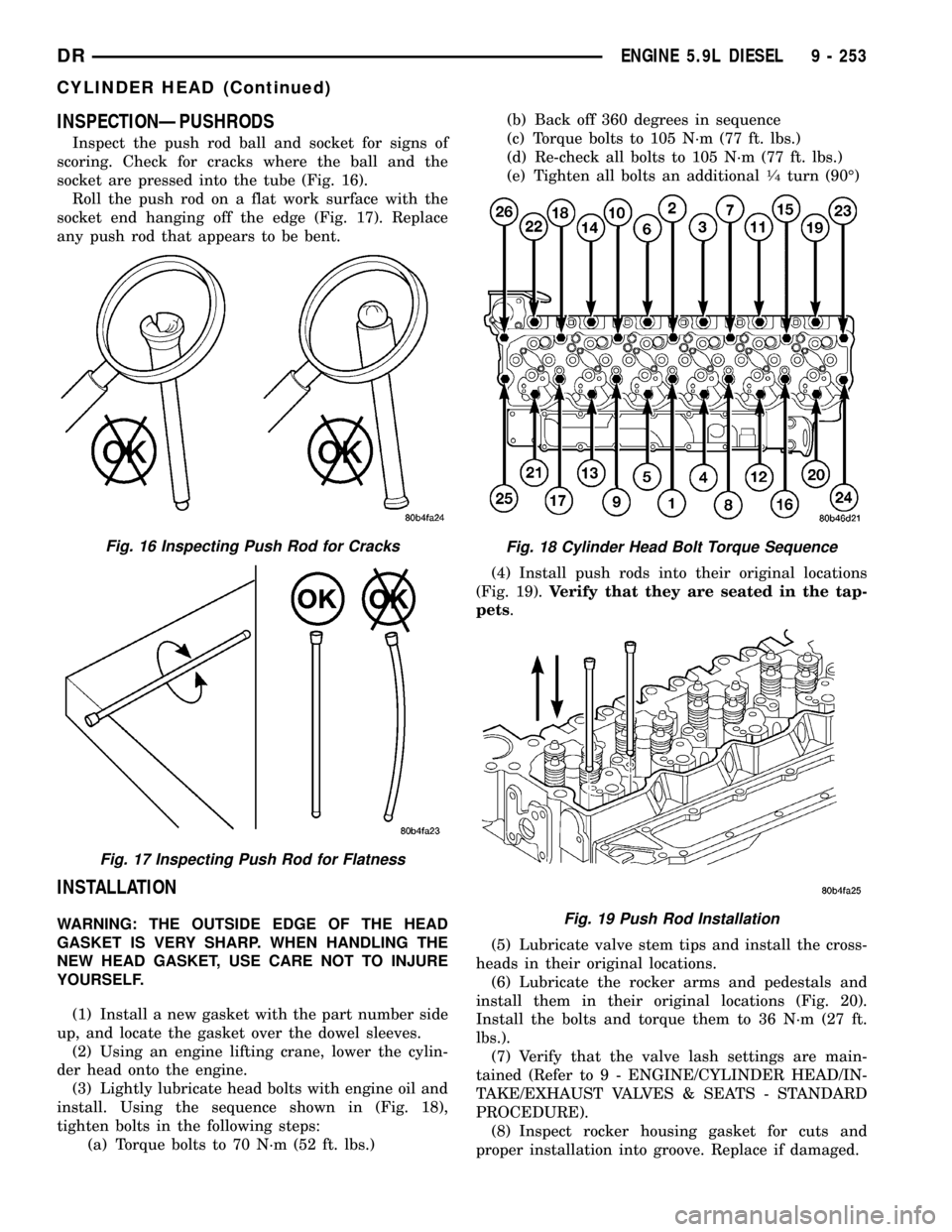
Inspect the push rod ball and socket for signs of
scoring. Check for cracks where the ball and the
socket are pressed into the tube (Fig. 16).
Roll the push rod on a flat work surface with the
socket end hanging off the edge (Fig. 17). Replace
any push rod that appears to be bent.
INSTALLATION
WARNING: THE OUTSIDE EDGE OF THE HEAD
GASKET IS VERY SHARP. WHEN HANDLING THE
NEW HEAD GASKET, USE CARE NOT TO INJURE
YOURSELF.
(1) Install a new gasket with the part number side
up, and locate the gasket over the dowel sleeves.
(2) Using an engine lifting crane, lower the cylin-
der head onto the engine.
(3) Lightly lubricate head bolts with engine oil and
install. Using the sequence shown in (Fig. 18),
tighten bolts in the following steps:
(a) Torque bolts to 70 N´m (52 ft. lbs.)(b) Back off 360 degrees in sequence
(c) Torque bolts to 105 N´m (77 ft. lbs.)
(d) Re-check all bolts to 105 N´m (77 ft. lbs.)
(e) Tighten all bolts an additional
1¤4turn (90É)
(4) Install push rods into their original locations
(Fig. 19).Verify that they are seated in the tap-
pets.
(5) Lubricate valve stem tips and install the cross-
heads in their original locations.
(6) Lubricate the rocker arms and pedestals and
install them in their original locations (Fig. 20).
Install the bolts and torque them to 36 N´m (27 ft.
lbs.).
(7) Verify that the valve lash settings are main-
tained (Refer to 9 - ENGINE/CYLINDER HEAD/IN-
TAKE/EXHAUST VALVES & SEATS - STANDARD
PROCEDURE).
(8) Inspect rocker housing gasket for cuts and
proper installation into groove. Replace if damaged.
Fig. 16 Inspecting Push Rod for Cracks
Fig. 17 Inspecting Push Rod for Flatness
Fig. 18 Cylinder Head Bolt Torque Sequence
Fig. 19 Push Rod Installation
DRENGINE 5.9L DIESEL 9 - 253
CYLINDER HEAD (Continued)