1998 DODGE RAM 1500 seats
[x] Cancel search: seatsPage 1252 of 2627
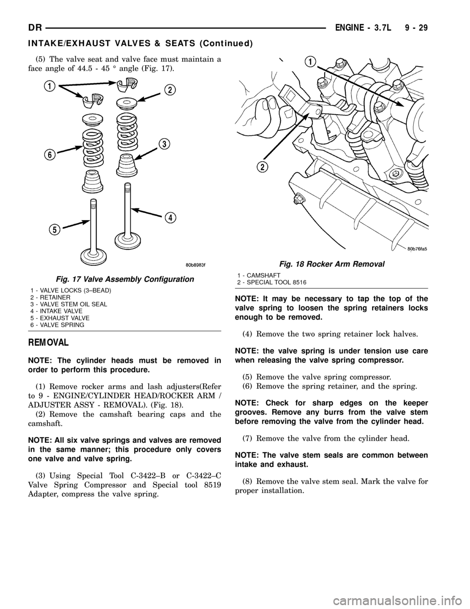
(5) The valve seat and valve face must maintain a
face angle of 44.5 - 45 É angle (Fig. 17).
REMOVAL
NOTE: The cylinder heads must be removed in
order to perform this procedure.
(1) Remove rocker arms and lash adjusters(Refer
to 9 - ENGINE/CYLINDER HEAD/ROCKER ARM /
ADJUSTER ASSY - REMOVAL). (Fig. 18).
(2) Remove the camshaft bearing caps and the
camshaft.
NOTE: All six valve springs and valves are removed
in the same manner; this procedure only covers
one valve and valve spring.
(3) Using Special Tool C-3422±B or C-3422±C
Valve Spring Compressor and Special tool 8519
Adapter, compress the valve spring.NOTE: It may be necessary to tap the top of the
valve spring to loosen the spring retainers locks
enough to be removed.
(4) Remove the two spring retainer lock halves.
NOTE: the valve spring is under tension use care
when releasing the valve spring compressor.
(5) Remove the valve spring compressor.
(6) Remove the spring retainer, and the spring.
NOTE: Check for sharp edges on the keeper
grooves. Remove any burrs from the valve stem
before removing the valve from the cylinder head.
(7) Remove the valve from the cylinder head.
NOTE: The valve stem seals are common between
intake and exhaust.
(8) Remove the valve stem seal. Mark the valve for
proper installation.
Fig. 17 Valve Assembly Configuration
1 - VALVE LOCKS (3±BEAD)
2 - RETAINER
3 - VALVE STEM OIL SEAL
4 - INTAKE VALVE
5 - EXHAUST VALVE
6 - VALVE SPRING
Fig. 18 Rocker Arm Removal
1 - CAMSHAFT
2 - SPECIAL TOOL 8516
DRENGINE - 3.7L 9 - 29
INTAKE/EXHAUST VALVES & SEATS (Continued)
Page 1253 of 2627
TESTING VALVE SPRINGS
NOTE: Whenever the valves are removed from the
cylinder head it is recommended that the valve
springs be inspected and tested for reuse.
Inspect the valve springs for physical signs of wear or
damage. Turn table of tool C-647 until surface is in line
with the 40.12 mm (1.579 in.) mark on the threaded
stud and the zero mark on the front. Place spring over
the stud on the table and lift compressing lever to set
tone device. Pull on torque wrench until a Ping is
heard. Take reading on torque wrench at this instant.
Multiply this reading by two. This will give the spring
load at test length. Fractional measurements are indi-
cated on the table for finer adjustments. Refer to Spec-
ifications Section to obtain specified height and
allowable tensions. Replace any springs that do not
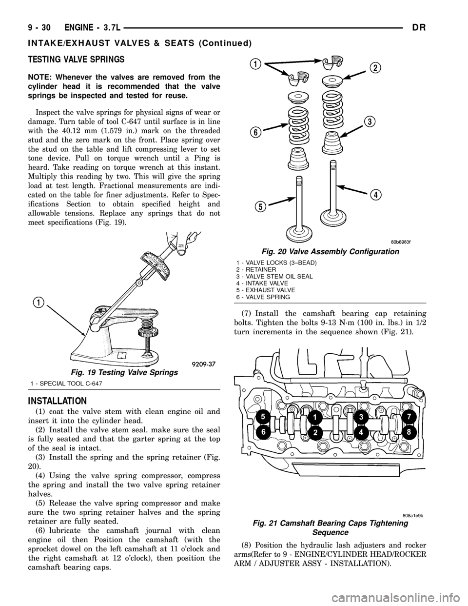
meet specifications (Fig. 19).
INSTALLATION
(1) coat the valve stem with clean engine oil and
insert it into the cylinder head.
(2) Install the valve stem seal. make sure the seal
is fully seated and that the garter spring at the top
of the seal is intact.
(3) Install the spring and the spring retainer (Fig.
20).
(4) Using the valve spring compressor, compress
the spring and install the two valve spring retainer
halves.
(5) Release the valve spring compressor and make
sure the two spring retainer halves and the spring
retainer are fully seated.
(6) lubricate the camshaft journal with clean
engine oil then Position the camshaft (with the
sprocket dowel on the left camshaft at 11 o'clock and
the right camshaft at 12 o'clock), then position the
camshaft bearing caps.(7) Install the camshaft bearing cap retaining
bolts. Tighten the bolts 9-13 N´m (100 in. lbs.) in 1/2
turn increments in the sequence shown (Fig. 21).
(8)
Position the hydraulic lash adjusters and rocker
arms(Refer to 9 - ENGINE/CYLINDER HEAD/ROCKER
ARM / ADJUSTER ASSY - INSTALLATION).
Fig. 19 Testing Valve Springs
1 - SPECIAL TOOL C-647
Fig. 20 Valve Assembly Configuration
1 - VALVE LOCKS (3±BEAD)
2 - RETAINER
3 - VALVE STEM OIL SEAL
4 - INTAKE VALVE
5 - EXHAUST VALVE
6 - VALVE SPRING
Fig. 21 Camshaft Bearing Caps Tightening
Sequence
9 - 30 ENGINE - 3.7LDR
INTAKE/EXHAUST VALVES & SEATS (Continued)
Page 1257 of 2627
INSTALLATION
NOTE: The cylinder head bolts are tightened using
a torque plus angle procedure. The bolts must be
examined BEFORE reuse. If the threads are necked
down the bolts should be replaced.
Necking can be checked by holding a straight edge
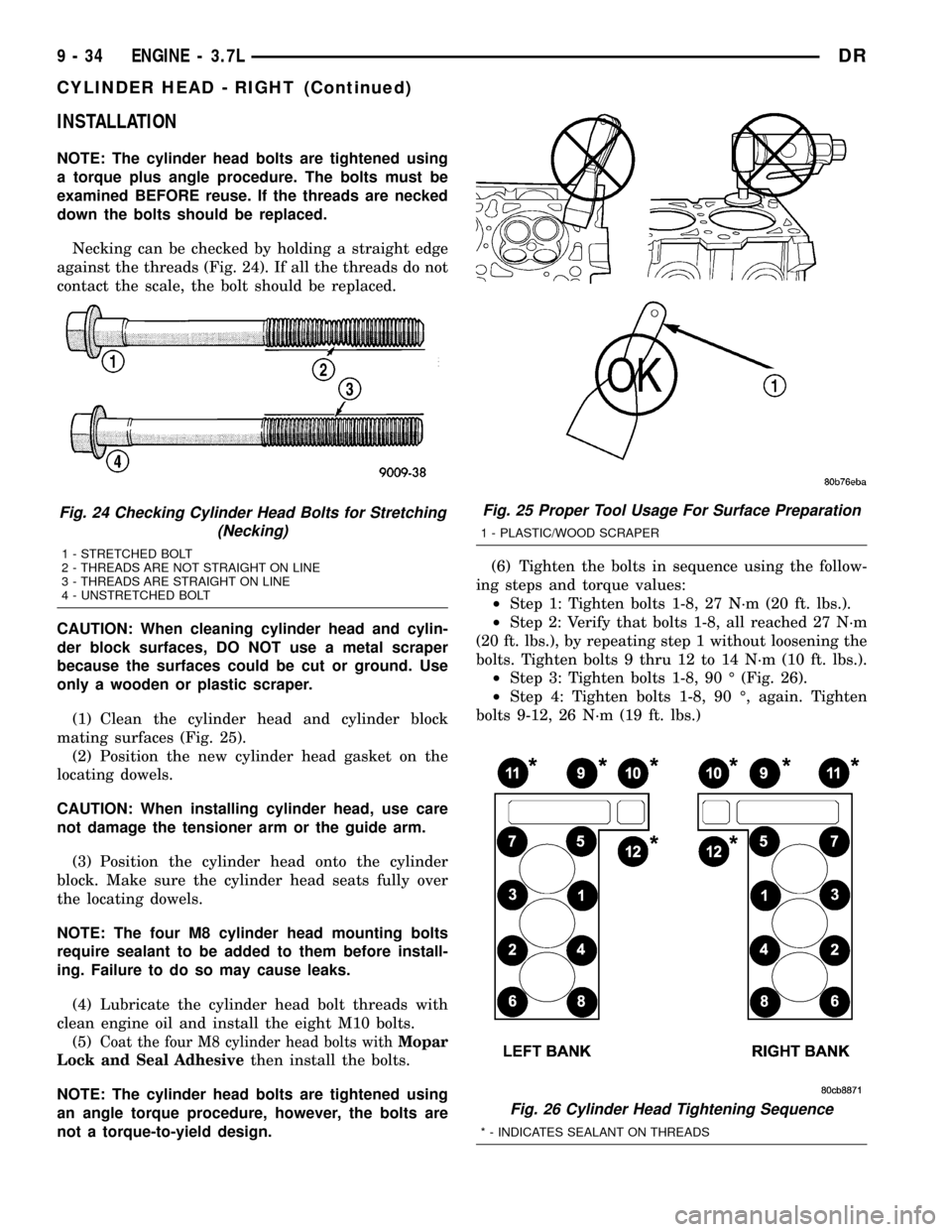
against the threads (Fig. 24). If all the threads do not
contact the scale, the bolt should be replaced.
CAUTION: When cleaning cylinder head and cylin-
der block surfaces, DO NOT use a metal scraper
because the surfaces could be cut or ground. Use
only a wooden or plastic scraper.
(1) Clean the cylinder head and cylinder block
mating surfaces (Fig. 25).
(2) Position the new cylinder head gasket on the
locating dowels.
CAUTION: When installing cylinder head, use care
not damage the tensioner arm or the guide arm.
(3) Position the cylinder head onto the cylinder
block. Make sure the cylinder head seats fully over
the locating dowels.
NOTE: The four M8 cylinder head mounting bolts
require sealant to be added to them before install-
ing. Failure to do so may cause leaks.
(4) Lubricate the cylinder head bolt threads with
clean engine oil and install the eight M10 bolts.
(5)
Coat the four M8 cylinder head bolts withMopar
Lock and Seal Adhesive
then install the bolts.
NOTE: The cylinder head bolts are tightened using
an angle torque procedure, however, the bolts are
not a torque-to-yield design.(6) Tighten the bolts in sequence using the follow-
ing steps and torque values:
²Step 1: Tighten bolts 1-8, 27 N´m (20 ft. lbs.).
²Step 2: Verify that bolts 1-8, all reached 27 N´m
(20 ft. lbs.), by repeating step 1 without loosening the
bolts. Tighten bolts 9 thru 12 to 14 N´m (10 ft. lbs.).
²Step 3: Tighten bolts 1-8, 90 É (Fig. 26).
²Step 4: Tighten bolts 1-8, 90 É, again. Tighten
bolts 9-12, 26 N´m (19 ft. lbs.)
Fig. 24 Checking Cylinder Head Bolts for Stretching
(Necking)
1 - STRETCHED BOLT
2 - THREADS ARE NOT STRAIGHT ON LINE
3 - THREADS ARE STRAIGHT ON LINE
4 - UNSTRETCHED BOLT
Fig. 25 Proper Tool Usage For Surface Preparation
1 - PLASTIC/WOOD SCRAPER
Fig. 26 Cylinder Head Tightening Sequence
* - INDICATES SEALANT ON THREADS
9 - 34 ENGINE - 3.7LDR
CYLINDER HEAD - RIGHT (Continued)
Page 1271 of 2627
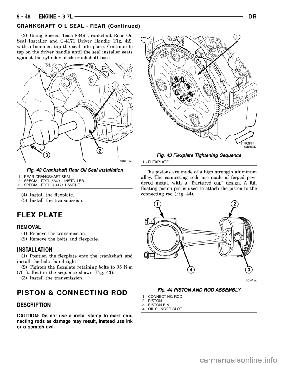
(3) Using Special Tools 8349 Crankshaft Rear Oil
Seal Installer and C-4171 Driver Handle (Fig. 42),
with a hammer, tap the seal into place. Continue to
tap on the driver handle until the seal installer seats
against the cylinder block crankshaft bore.
(4) Install the flexplate.
(5) Install the transmission.
FLEX PLATE
REMOVAL
(1) Remove the transmission.
(2) Remove the bolts and flexplate.
INSTALLATION
(1) Position the flexplate onto the crankshaft and
install the bolts hand tight.
(2) Tighten the flexplate retaining bolts to 95 N´m
(70 ft. lbs.) in the sequence shown (Fig. 43).
(3) Install the transmission.
PISTON & CONNECTING ROD
DESCRIPTION
CAUTION: Do not use a metal stamp to mark con-
necting rods as damage may result, instead use ink
or a scratch awl.The pistons are made of a high strength aluminum
alloy. The connecting rods are made of forged pow-
dered metal, with a ªfractured capº design. A full
floating piston pin is used to attach the piston to the
connecting rod (Fig. 44).
Fig. 42 Crankshaft Rear Oil Seal Installation
1 - REAR CRANKSHAFT SEAL
2 - SPECIAL TOOL 8349-1 INSTALLER
3 - SPECIAL TOOL C-4171 HANDLE
Fig. 43 Flexplate Tightening Sequence
1 - FLEXPLATE
Fig. 44 PISTON AND ROD ASSEMBLY
1 - CONNECTING ROD
2 - PISTON
3 - PISTON PIN
4 - OIL SLINGER SLOT
9 - 48 ENGINE - 3.7LDR
CRANKSHAFT OIL SEAL - REAR (Continued)
Page 1311 of 2627
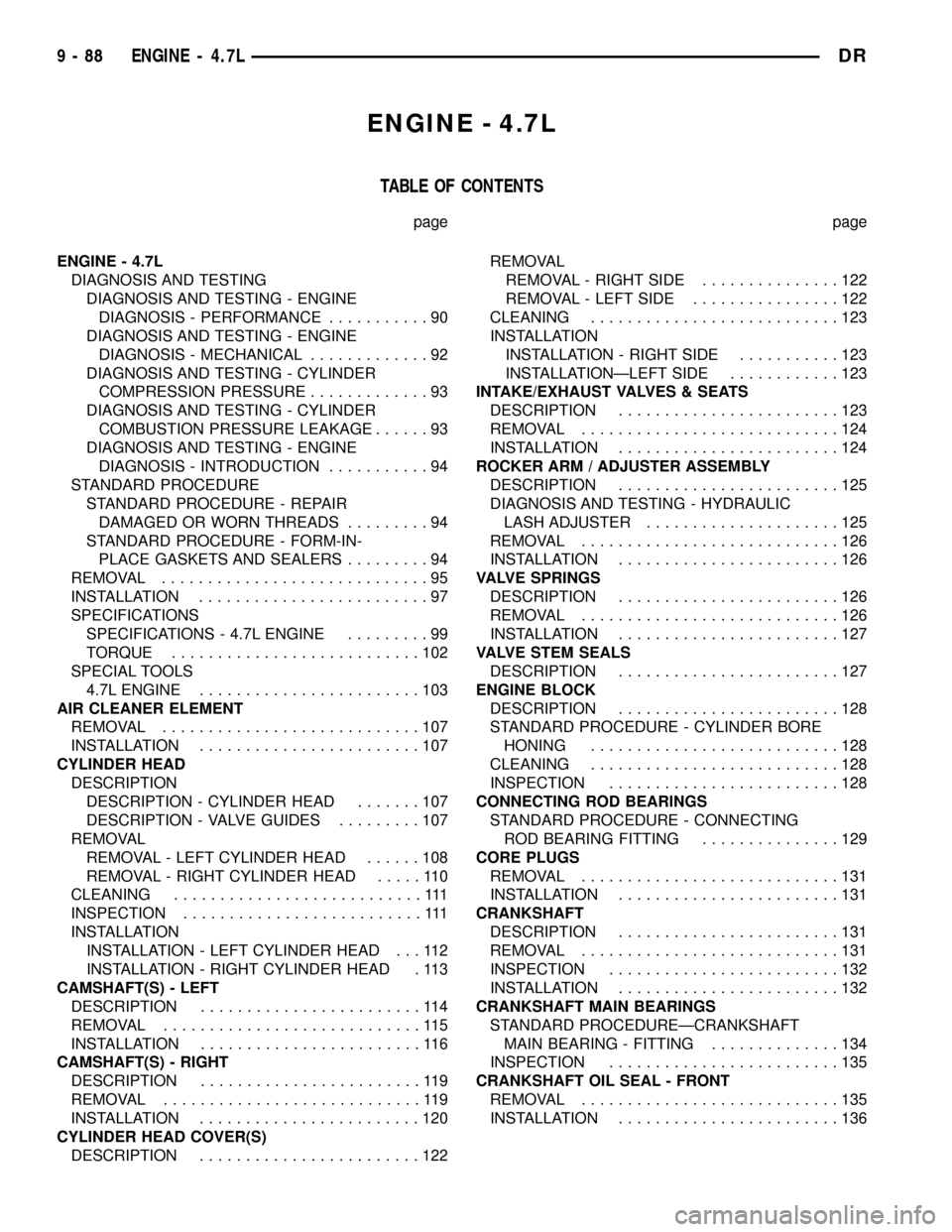
ENGINE - 4.7L
TABLE OF CONTENTS
page page
ENGINE - 4.7L
DIAGNOSIS AND TESTING
DIAGNOSIS AND TESTING - ENGINE
DIAGNOSIS - PERFORMANCE...........90
DIAGNOSIS AND TESTING - ENGINE
DIAGNOSIS - MECHANICAL.............92
DIAGNOSIS AND TESTING - CYLINDER
COMPRESSION PRESSURE.............93
DIAGNOSIS AND TESTING - CYLINDER
COMBUSTION PRESSURE LEAKAGE......93
DIAGNOSIS AND TESTING - ENGINE
DIAGNOSIS - INTRODUCTION...........94
STANDARD PROCEDURE
STANDARD PROCEDURE - REPAIR
DAMAGED OR WORN THREADS.........94
STANDARD PROCEDURE - FORM-IN-
PLACE GASKETS AND SEALERS.........94
REMOVAL.............................95
INSTALLATION.........................97
SPECIFICATIONS
SPECIFICATIONS - 4.7L ENGINE.........99
TORQUE...........................102
SPECIAL TOOLS
4.7L ENGINE........................103
AIR CLEANER ELEMENT
REMOVAL............................107
INSTALLATION........................107
CYLINDER HEAD
DESCRIPTION
DESCRIPTION - CYLINDER HEAD.......107
DESCRIPTION - VALVE GUIDES.........107
REMOVAL
REMOVAL - LEFT CYLINDER HEAD......108
REMOVAL - RIGHT CYLINDER HEAD.....110
CLEANING...........................111
INSPECTION..........................111
INSTALLATION
INSTALLATION - LEFT CYLINDER HEAD . . . 112
INSTALLATION - RIGHT CYLINDER HEAD . 113
CAMSHAFT(S) - LEFT
DESCRIPTION........................114
REMOVAL............................115
INSTALLATION........................116
CAMSHAFT(S) - RIGHT
DESCRIPTION........................119
REMOVAL............................119
INSTALLATION........................120
CYLINDER HEAD COVER(S)
DESCRIPTION........................122REMOVAL
REMOVAL - RIGHT SIDE...............122
REMOVAL - LEFT SIDE................122
CLEANING...........................123
INSTALLATION
INSTALLATION - RIGHT SIDE...........123
INSTALLATIONÐLEFT SIDE............123
INTAKE/EXHAUST VALVES & SEATS
DESCRIPTION........................123
REMOVAL............................124
INSTALLATION........................124
ROCKER ARM / ADJUSTER ASSEMBLY
DESCRIPTION........................125
DIAGNOSIS AND TESTING - HYDRAULIC
LASH ADJUSTER.....................125
REMOVAL............................126
INSTALLATION........................126
VALVE SPRINGS
DESCRIPTION........................126
REMOVAL............................126
INSTALLATION........................127
VALVE STEM SEALS
DESCRIPTION........................127
ENGINE BLOCK
DESCRIPTION........................128
STANDARD PROCEDURE - CYLINDER BORE
HONING...........................128
CLEANING...........................128
INSPECTION.........................128
CONNECTING ROD BEARINGS
STANDARD PROCEDURE - CONNECTING
ROD BEARING FITTING...............129
CORE PLUGS
REMOVAL............................131
INSTALLATION........................131
CRANKSHAFT
DESCRIPTION........................131
REMOVAL............................131
INSPECTION.........................132
INSTALLATION........................132
CRANKSHAFT MAIN BEARINGS
STANDARD PROCEDUREÐCRANKSHAFT
MAIN BEARING - FITTING..............134
INSPECTION.........................135
CRANKSHAFT OIL SEAL - FRONT
REMOVAL............................135
INSTALLATION........................136
9 - 88 ENGINE - 4.7LDR
Page 1315 of 2627
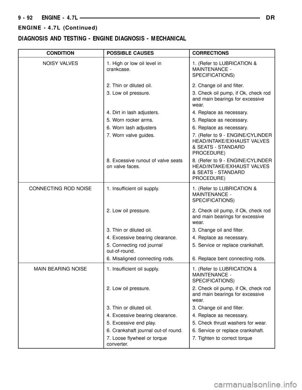
DIAGNOSIS AND TESTING - ENGINE DIAGNOSIS - MECHANICAL
CONDITION POSSIBLE CAUSES CORRECTIONS
NOISY VALVES 1. High or low oil level in
crankcase.1. (Refer to LUBRICATION &
MAINTENANCE -
SPECIFICATIONS)
2. Thin or diluted oil. 2. Change oil and filter.
3. Low oil pressure. 3. Check oil pump, if Ok, check rod
and main bearings for excessive
wear.
4. Dirt in lash adjusters. 4. Replace as necessary.
5. Worn rocker arms. 5. Replace as necessary.
6. Worn lash adjusters 6. Replace as necessary.
7. Worn valve guides. 7. (Refer to 9 - ENGINE/CYLINDER
HEAD/INTAKE/EXHAUST VALVES
& SEATS - STANDARD
PROCEDURE)
8. Excessive runout of valve seats
on valve faces.8. (Refer to 9 - ENGINE/CYLINDER
HEAD/INTAKE/EXHAUST VALVES
& SEATS - STANDARD
PROCEDURE)
CONNECTING ROD NOISE 1. Insufficient oil supply. 1. (Refer to LUBRICATION &
MAINTENANCE -
SPECIFICATIONS)
2. Low oil pressure. 2. Check oil pump, if Ok, check rod
and main bearings for excessive
wear.
3. Thin or diluted oil. 3. Change oil and filter.
4. Excessive bearing clearance. 4. Replace as necessary.
5. Connecting rod journal
out-of-round.5. Service or replace crankshaft.
6. Misaligned connecting rods. 6. Replace bent connecting rods.
MAIN BEARING NOISE 1. Insufficient oil supply. 1. (Refer to LUBRICATION &
MAINTENANCE -
SPECIFICATIONS)
2. Low oil pressure. 2. Check oil pump, if Ok, check rod
and main bearings for excessive
wear.
3. Thin or diluted oil. 3. Change oil and filter.
4. Excessive bearing clearance. 4. Replace as necessary.
5. Excessive end play. 5. Check thrust washers for wear.
6. Crankshaft journal out-of round. 6. Service or replace crankshaft.
7. Loose flywheel or torque
converter.7. Tighten to correct torque
9 - 92 ENGINE - 4.7LDR
ENGINE - 4.7L (Continued)
Page 1334 of 2627
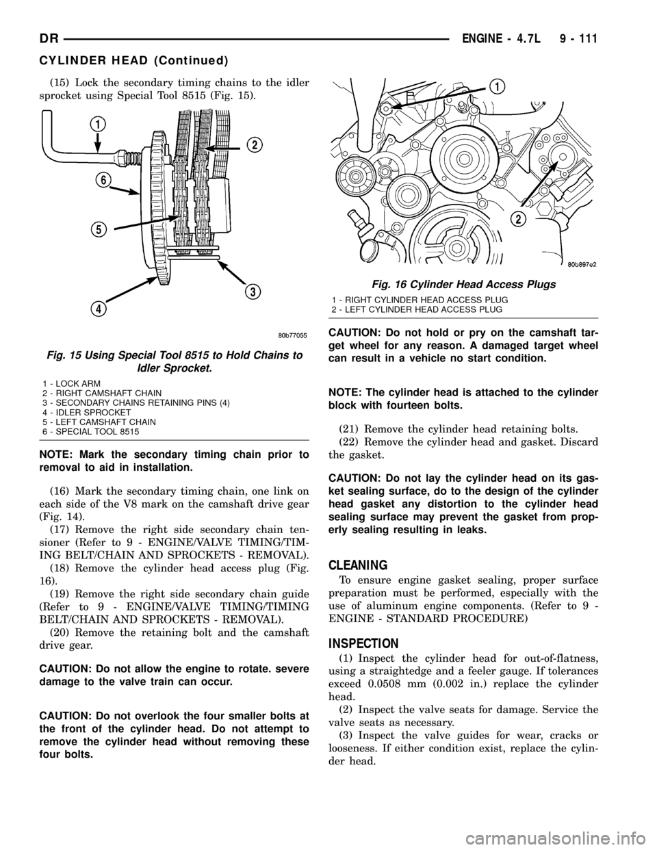
(15) Lock the secondary timing chains to the idler
sprocket using Special Tool 8515 (Fig. 15).
NOTE: Mark the secondary timing chain prior to
removal to aid in installation.
(16) Mark the secondary timing chain, one link on
each side of the V8 mark on the camshaft drive gear
(Fig. 14).
(17) Remove the right side secondary chain ten-
sioner (Refer to 9 - ENGINE/VALVE TIMING/TIM-
ING BELT/CHAIN AND SPROCKETS - REMOVAL).
(18) Remove the cylinder head access plug (Fig.
16).
(19) Remove the right side secondary chain guide
(Refer to 9 - ENGINE/VALVE TIMING/TIMING
BELT/CHAIN AND SPROCKETS - REMOVAL).
(20) Remove the retaining bolt and the camshaft
drive gear.
CAUTION: Do not allow the engine to rotate. severe
damage to the valve train can occur.
CAUTION: Do not overlook the four smaller bolts at
the front of the cylinder head. Do not attempt to
remove the cylinder head without removing these
four bolts.CAUTION: Do not hold or pry on the camshaft tar-
get wheel for any reason. A damaged target wheel
can result in a vehicle no start condition.
NOTE: The cylinder head is attached to the cylinder
block with fourteen bolts.
(21) Remove the cylinder head retaining bolts.
(22) Remove the cylinder head and gasket. Discard
the gasket.
CAUTION: Do not lay the cylinder head on its gas-
ket sealing surface, do to the design of the cylinder
head gasket any distortion to the cylinder head
sealing surface may prevent the gasket from prop-
erly sealing resulting in leaks.
CLEANING
To ensure engine gasket sealing, proper surface
preparation must be performed, especially with the
use of aluminum engine components. (Refer to 9 -
ENGINE - STANDARD PROCEDURE)
INSPECTION
(1) Inspect the cylinder head for out-of-flatness,
using a straightedge and a feeler gauge. If tolerances
exceed 0.0508 mm (0.002 in.) replace the cylinder
head.
(2) Inspect the valve seats for damage. Service the
valve seats as necessary.
(3) Inspect the valve guides for wear, cracks or
looseness. If either condition exist, replace the cylin-
der head.
Fig. 15 Using Special Tool 8515 to Hold Chains to
Idler Sprocket.
1 - LOCK ARM
2 - RIGHT CAMSHAFT CHAIN
3 - SECONDARY CHAINS RETAINING PINS (4)
4 - IDLER SPROCKET
5 - LEFT CAMSHAFT CHAIN
6 - SPECIAL TOOL 8515
Fig. 16 Cylinder Head Access Plugs
1 - RIGHT CYLINDER HEAD ACCESS PLUG
2 - LEFT CYLINDER HEAD ACCESS PLUG
DRENGINE - 4.7L 9 - 111
CYLINDER HEAD (Continued)
Page 1335 of 2627
INSTALLATION
INSTALLATION - LEFT CYLINDER HEAD
NOTE: The cylinder head bolts are tightened using
a torque plus angle procedure. The bolts must be
examined BEFORE reuse. If the threads are necked
down the bolts should be replaced.
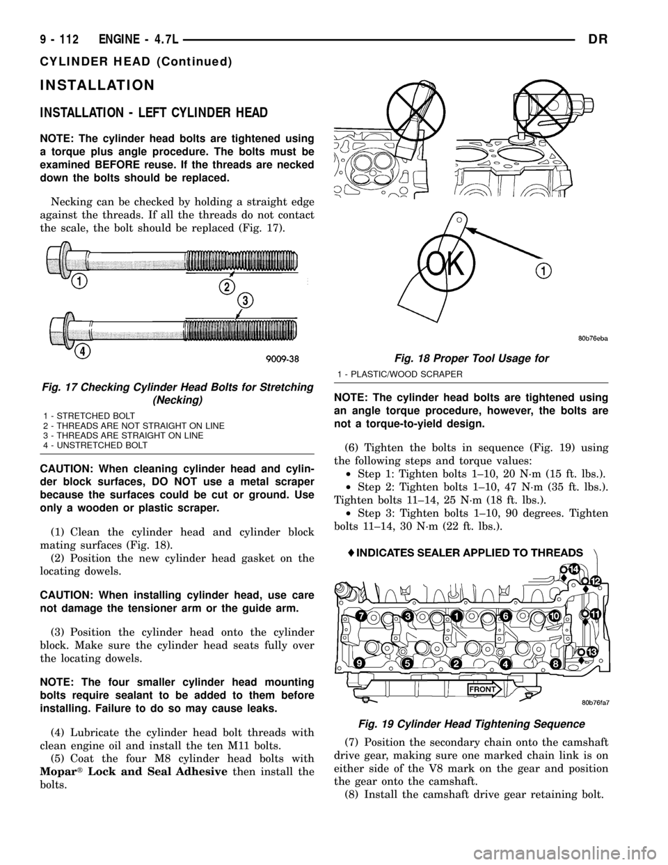
Necking can be checked by holding a straight edge
against the threads. If all the threads do not contact
the scale, the bolt should be replaced (Fig. 17).
CAUTION: When cleaning cylinder head and cylin-
der block surfaces, DO NOT use a metal scraper
because the surfaces could be cut or ground. Use
only a wooden or plastic scraper.
(1) Clean the cylinder head and cylinder block
mating surfaces (Fig. 18).
(2) Position the new cylinder head gasket on the
locating dowels.
CAUTION: When installing cylinder head, use care
not damage the tensioner arm or the guide arm.
(3) Position the cylinder head onto the cylinder
block. Make sure the cylinder head seats fully over
the locating dowels.
NOTE: The four smaller cylinder head mounting
bolts require sealant to be added to them before
installing. Failure to do so may cause leaks.
(4) Lubricate the cylinder head bolt threads with
clean engine oil and install the ten M11 bolts.
(5) Coat the four M8 cylinder head bolts with
MopartLock and Seal Adhesivethen install the
bolts.NOTE: The cylinder head bolts are tightened using
an angle torque procedure, however, the bolts are
not a torque-to-yield design.
(6) Tighten the bolts in sequence (Fig. 19) using
the following steps and torque values:
²Step 1: Tighten bolts 1±10, 20 N´m (15 ft. lbs.).
²Step 2: Tighten bolts 1±10, 47 N´m (35 ft. lbs.).
Tighten bolts 11±14, 25 N´m (18 ft. lbs.).
²Step 3: Tighten bolts 1±10, 90 degrees. Tighten
bolts 11±14, 30 N´m (22 ft. lbs.).
(7) Position the secondary chain onto the camshaft
drive gear, making sure one marked chain link is on
either side of the V8 mark on the gear and position
the gear onto the camshaft.
(8) Install the camshaft drive gear retaining bolt.
Fig. 17 Checking Cylinder Head Bolts for Stretching
(Necking)
1 - STRETCHED BOLT
2 - THREADS ARE NOT STRAIGHT ON LINE
3 - THREADS ARE STRAIGHT ON LINE
4 - UNSTRETCHED BOLT
Fig. 18 Proper Tool Usage for
1 - PLASTIC/WOOD SCRAPER
Fig. 19 Cylinder Head Tightening Sequence
9 - 112 ENGINE - 4.7LDR
CYLINDER HEAD (Continued)