1998 DODGE RAM 1500 seats
[x] Cancel search: seatsPage 2005 of 2627
UPPER AND LOWER HOUSING
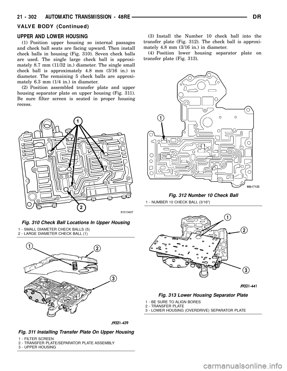
(1) Position upper housing so internal passages
and check ball seats are facing upward. Then install
check balls in housing (Fig. 310). Seven check balls
are used. The single large check ball is approxi-
mately 8.7 mm (11/32 in.) diameter. The single small
check ball is approximately 4.8 mm (3/16 in.) in
diameter. The remaining 5 check balls are approxi-
mately 6.3 mm (1/4 in.) in diameter.
(2) Position assembled transfer plate and upper
housing separator plate on upper housing (Fig. 311).
Be sure filter screen is seated in proper housing
recess.(3) Install the Number 10 check ball into the
transfer plate (Fig. 312). The check ball is approxi-
mately 4.8 mm (3/16 in.) in diameter.
(4) Position lower housing separator plate on
transfer plate (Fig. 313).
Fig. 310 Check Ball Locations In Upper Housing
1 - SMALL DIAMETER CHECK BALLS (5)
2 - LARGE DIAMETER CHECK BALL (1)
Fig. 311 Installing Transfer Plate On Upper Housing
1 - FILTER SCREEN
2 - TRANSFER PLATE/SEPARATOR PLATE ASSEMBLY
3 - UPPER HOUSING
Fig. 312 Number 10 Check Ball
1 - NUMBER 10 CHECK BALL (3/169)
Fig. 313 Lower Housing Separator Plate
1 - BE SURE TO ALIGN BORES
2 - TRANSFER PLATE
3 - LOWER HOUSING (OVERDRIVE) SEPARATOR PLATE
21 - 302 AUTOMATIC TRANSMISSION - 48REDR
VALVE BODY (Continued)
Page 2296 of 2627
BODY
TABLE OF CONTENTS
page page
BODY
WARNING
SAFETY PRECAUTIONS AND WARNINGS . . . 1
DIAGNOSIS AND TESTING
DIAGNOSIS AND TESTING - WATER LEAKS . 1
DIAGNOSIS AND TESTING - WIND NOISE . . . 2
STANDARD PROCEDURE
STANDARD PROCEDURE - BODY
LUBRICATION.........................3
STANDARD PROCEDURE - HEAT STAKING . . 3
STANDARD PROCEDURE - PLASTIC BODY
PANEL REPAIR........................3
STANDARD PROCEDURE - BUZZ, SQUEAK
& RATTLE...........................11
SPECIFICATIONS - TORQUE..............12SPECIAL TOOLS
BODY..............................14
TAILGATE..............................15
DOOR - FRONT.........................18
DOORS - REAR.........................28
EXTERIOR.............................36
HOOD.................................46
INSTRUMENT PANEL.....................49
INTERIOR..............................62
PAINT.................................73
SEATS................................75
STATIONARY GLASS.....................86
WEATHERSTRIP/SEALS...................91
BODY STRUCTURE......................95
BODY
WARNING
SAFETY PRECAUTIONS AND WARNINGS
WARNING: USE AN OSHA APPROVED BREATHING
FILTER WHEN SPRAYING PAINT OR SOLVENTS IN
A CONFINED AREA. PERSONAL INJURY CAN
RESULT.
²AVOID PROLONGED SKIN CONTACT WITH
PETROLEUM OR ALCOHOL ± BASED CLEANING
SOLVENTS. PERSONAL INJURY CAN RESULT.
²DO NOT STAND UNDER A HOISTED VEHICLE
THAT IS NOT PROPERLY SUPPORTED ON SAFETY
STANDS. PERSONAL INJURY CAN RESULT.
CAUTION: When holes must be drilled or punched
in an inner body panel, verify depth of space to the
outer body panel, electrical wiring, or other compo-
nents. Damage to vehicle can result.
²Do not weld exterior panels unless combustible
material on the interior of vehicle is removed from
the repair area. Fire or hazardous conditions, can
result.
²Always have a fire extinguisher ready for use
when welding.
²Disconnect the negative (-) cable clamp from
the battery when servicing electrical components
that are live when the ignition is OFF. Damage to
electrical system can result.²Do not use abrasive chemicals or compounds
on painted surfaces. Damage to finish can result.
²Do not use harsh alkaline based cleaning sol-
vents on painted or upholstered surfaces. Damage
to finish or color can result.
²Do not hammer or pound on plastic trim panel
when servicing interior trim. Plastic panels can
break.
DIAGNOSIS AND TESTING
DIAGNOSIS AND TESTING - WATER LEAKS
Water leaks can be caused by poor sealing,
improper body component alignment, body seam
porosity, missing plugs, or blocked drain holes. Cen-
trifugal and gravitational force can cause water to
drip from a location away from the actual leak point,
making leak detection difficult. All body sealing
points should be water tight in normal wet-driving
conditions. Water flowing downward from the front of
the vehicle should not enter the passenger or luggage
compartment. Moving sealing surfaces will not
always seal water tight under all conditions. At
times, side glass or door seals will allow water to
enter the passenger compartment during high pres-
sure washing or hard driving rain (severe) condi-
tions. Overcompensating on door or glass
adjustments to stop a water leak that occurs under
severe conditions can cause premature seal wear and
excessive closing or latching effort. After completing
a repair, water test vehicle to verify leak has stopped
before returning vehicle to use.
DRBODY 23 - 1
Page 2339 of 2627
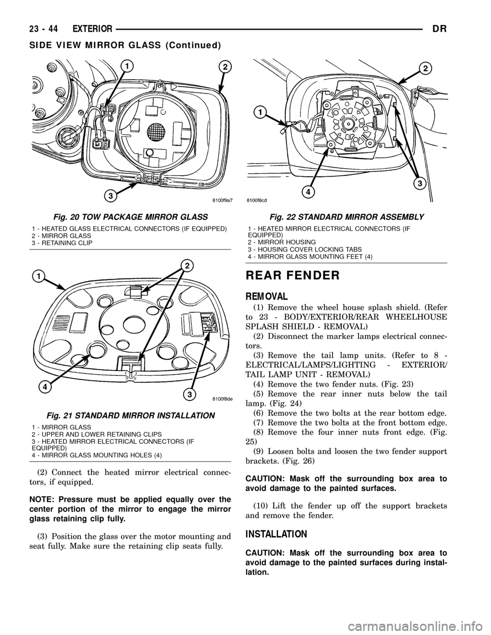
(2) Connect the heated mirror electrical connec-
tors, if equipped.
NOTE: Pressure must be applied equally over the
center portion of the mirror to engage the mirror
glass retaining clip fully.
(3) Position the glass over the motor mounting and
seat fully. Make sure the retaining clip seats fully.
REAR FENDER
REMOVAL
(1) Remove the wheel house splash shield. (Refer
to 23 - BODY/EXTERIOR/REAR WHEELHOUSE
SPLASH SHIELD - REMOVAL)
(2) Disconnect the marker lamps electrical connec-
tors.
(3) Remove the tail lamp units. (Refer to 8 -
ELECTRICAL/LAMPS/LIGHTING - EXTERIOR/
TAIL LAMP UNIT - REMOVAL)
(4) Remove the two fender nuts. (Fig. 23)
(5) Remove the rear inner nuts below the tail
lamp. (Fig. 24)
(6) Remove the two bolts at the rear bottom edge.
(7) Remove the two bolts at the front bottom edge.
(8) Remove the four inner nuts front edge. (Fig.
25)
(9) Loosen bolts and loosen the two fender support
brackets. (Fig. 26)
CAUTION: Mask off the surrounding box area to
avoid damage to the painted surfaces.
(10) Lift the fender up off the support brackets
and remove the fender.
INSTALLATION
CAUTION: Mask off the surrounding box area to
avoid damage to the painted surfaces during instal-
lation.
Fig. 20 TOW PACKAGE MIRROR GLASS
1 - HEATED GLASS ELECTRICAL CONNECTORS (IF EQUIPPED)
2 - MIRROR GLASS
3 - RETAINING CLIP
Fig. 21 STANDARD MIRROR INSTALLATION
1 - MIRROR GLASS
2 - UPPER AND LOWER RETAINING CLIPS
3 - HEATED MIRROR ELECTRICAL CONNECTORS (IF
EQUIPPED)
4 - MIRROR GLASS MOUNTING HOLES (4)
Fig. 22 STANDARD MIRROR ASSEMBLY
1 - HEATED MIRROR ELECTRICAL CONNECTORS (IF
EQUIPPED)
2 - MIRROR HOUSING
3 - HOUSING COVER LOCKING TABS
4 - MIRROR GLASS MOUNTING FEET (4)
23 - 44 EXTERIORDR
SIDE VIEW MIRROR GLASS (Continued)
Page 2360 of 2627
CARPETS AND FLOOR MATS
REMOVAL
(1) Remove the front seats. (Refer to 23 - BODY/
SEATS/SEAT - FRONT - REMOVAL)
(2) Remove the rear seats, if equipped. (Refer to 23
- BODY/SEATS/SEAT - REAR - REMOVAL)(3) Remove the floor console, if equipped. (Refer to
23 - BODY/INTERIOR/FLOOR CONSOLE -
REMOVAL)
(4) Remove the lower b-pillar trim. (Refer to 23 -
BODY/INTERIOR/B-PILLAR LOWER TRIM -
REMOVAL)
(5) On quad cab models, remove the lower seat
belt anchor next to the b-pillar.
(6) Using a trim stick C-4755 or equivalent,
remove the rear cup holder, if equipped.
(7) Remove the jack assembly.
(8) Remove the carpet.
INSTALLATION
(1) Install the carpet.
(2) Install the jack assembly.
(3) Install the rear cup holder, if equipped.
(4) Install the lower b-pillar trim. (Refer to 23 -
BODY/INTERIOR/B-PILLAR LOWER TRIM -
INSTALLATION)
(5) On quad cab models, install the lower seatbelt
anchor bolt next to the b-pillar and tighten to 40 N´m
(30 ft. lbs.).
(6) Install the floor console, if equipped. (Refer to
23 - BODY/INTERIOR/FLOOR CONSOLE - INSTAL-
LATION)
(7) Install the rear seats, if equipped. (Refer to 23
- BODY/SEATS/SEAT - REAR - INSTALLATION)
(8) Install the front seats. (Refer to 23 - BODY/
SEATS/SEAT - FRONT - INSTALLATION)
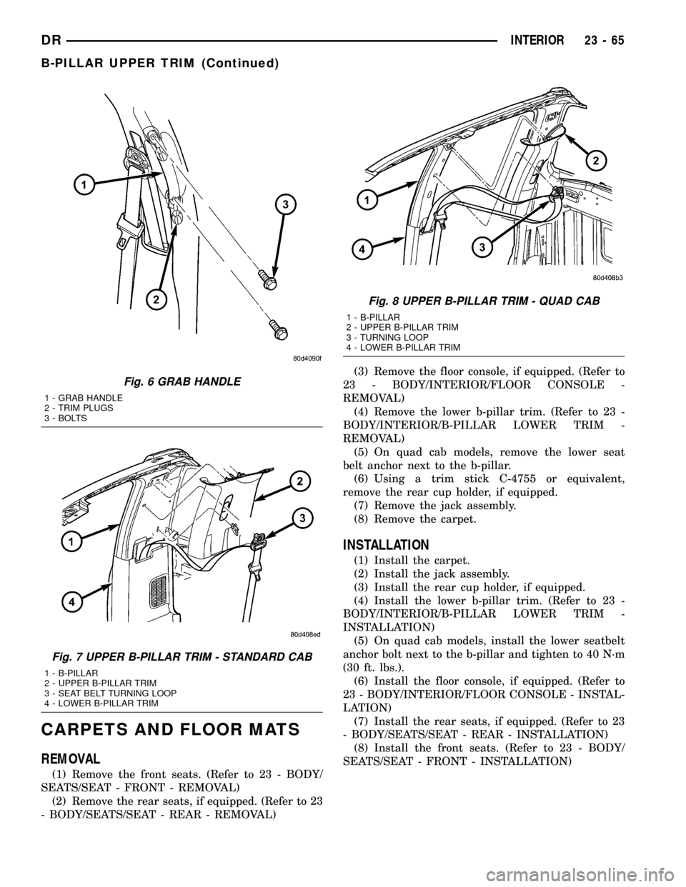
Fig. 6 GRAB HANDLE
1 - GRAB HANDLE
2 - TRIM PLUGS
3 - BOLTS
Fig. 7 UPPER B-PILLAR TRIM - STANDARD CAB
1 - B-PILLAR
2 - UPPER B-PILLAR TRIM
3 - SEAT BELT TURNING LOOP
4 - LOWER B-PILLAR TRIM
Fig. 8 UPPER B-PILLAR TRIM - QUAD CAB
1 - B-PILLAR
2 - UPPER B-PILLAR TRIM
3 - TURNING LOOP
4 - LOWER B-PILLAR TRIM
DRINTERIOR 23 - 65
B-PILLAR UPPER TRIM (Continued)
Page 2361 of 2627
COAT HOOK
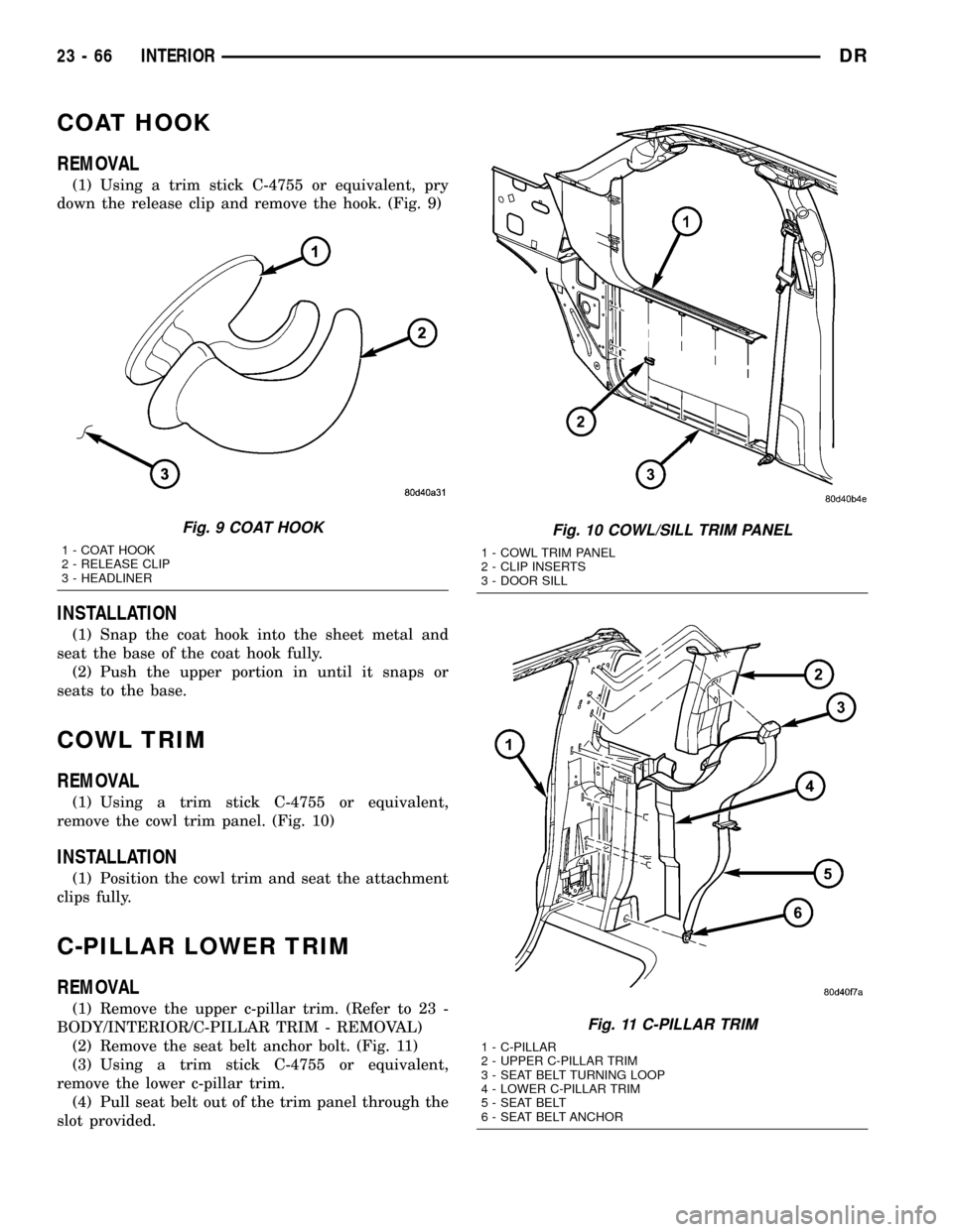
REMOVAL
(1) Using a trim stick C-4755 or equivalent, pry
down the release clip and remove the hook. (Fig. 9)
INSTALLATION
(1) Snap the coat hook into the sheet metal and
seat the base of the coat hook fully.
(2) Push the upper portion in until it snaps or
seats to the base.
COWL TRIM
REMOVAL
(1) Using a trim stick C-4755 or equivalent,
remove the cowl trim panel. (Fig. 10)
INSTALLATION
(1) Position the cowl trim and seat the attachment
clips fully.
C-PILLAR LOWER TRIM
REMOVAL
(1) Remove the upper c-pillar trim. (Refer to 23 -
BODY/INTERIOR/C-PILLAR TRIM - REMOVAL)
(2) Remove the seat belt anchor bolt. (Fig. 11)
(3) Using a trim stick C-4755 or equivalent,
remove the lower c-pillar trim.
(4) Pull seat belt out of the trim panel through the
slot provided.
Fig. 9 COAT HOOK
1 - COAT HOOK
2 - RELEASE CLIP
3 - HEADLINER
Fig. 10 COWL/SILL TRIM PANEL
1 - COWL TRIM PANEL
2 - CLIP INSERTS
3 - DOOR SILL
Fig. 11 C-PILLAR TRIM
1 - C-PILLAR
2 - UPPER C-PILLAR TRIM
3 - SEAT BELT TURNING LOOP
4 - LOWER C-PILLAR TRIM
5 - SEAT BELT
6 - SEAT BELT ANCHOR
23 - 66 INTERIORDR
Page 2370 of 2627
SEATS
TABLE OF CONTENTS
page page
CENTER SEAT
REMOVAL.............................75
INSTALLATION.........................76
CENTER ARMREST / SEAT BACK
REMOVAL.............................76
INSTALLATION.........................77
CENTER SEAT BACK INERTIA HINGE COVER
REMOVAL.............................77
INSTALLATION.........................77
CENTER SEAT BACK HINGE
REMOVAL.............................78
INSTALLATION.........................79
CENTER SEAT BACK LID
REMOVAL.............................79
INSTALLATION.........................79
CENTER SEAT CUSHION
REMOVAL.............................79
INSTALLATION.........................79
CENTER SEAT CUSHION COVER
REMOVAL.............................79
INSTALLATION.........................79
UNDER SEAT STORAGE BIN LID
REMOVAL.............................80
INSTALLATION.........................80
UNDER SEAT STORAGE BIN
REMOVAL.............................80
INSTALLATION.........................80
UNDER SEAT STORAGE BIN COVERING
REMOVAL.............................80
INSTALLATION.........................80
UNDER SEAT STORAGE BIN LATCH
REMOVAL.............................80
INSTALLATION.........................80
HEADREST
REMOVAL.............................80
INSTALLATION.........................80
HEADREST SLEEVE
REMOVAL.............................81INSTALLATION.........................81
SEAT - FRONT
REMOVAL.............................81
INSTALLATION.........................81
LUMBAR SUPPORT HANDLE/BEZEL
REMOVAL.............................82
INSTALLATION.........................82
SEAT BACK CUSHION / COVER - FRONT
REMOVAL.............................82
INSTALLATION.........................82
SEAT CUSHION / COVER - FRONT
REMOVAL.............................83
INSTALLATION.........................83
SEAT TRACK
REMOVAL.............................83
INSTALLATION.........................83
SEAT - REAR
REMOVAL.............................83
INSTALLATION.........................83
SEAT BACK - REAR
REMOVAL.............................83
INSTALLATION.........................83
SEAT BACK CUSHION / COVER - REAR
REMOVAL.............................84
INSTALLATION.........................84
SEAT CUSHION / COVER - REAR
REMOVAL.............................84
INSTALLATION.........................84
SEAT CUSHION FRAME - REAR
REMOVAL.............................85
INSTALLATION.........................85
SEAT BACK REAR - FOOTMANS LOOP
BRACKETS
REMOVAL.............................85
INSTALLATION.........................85
CENTER SEAT
REMOVAL
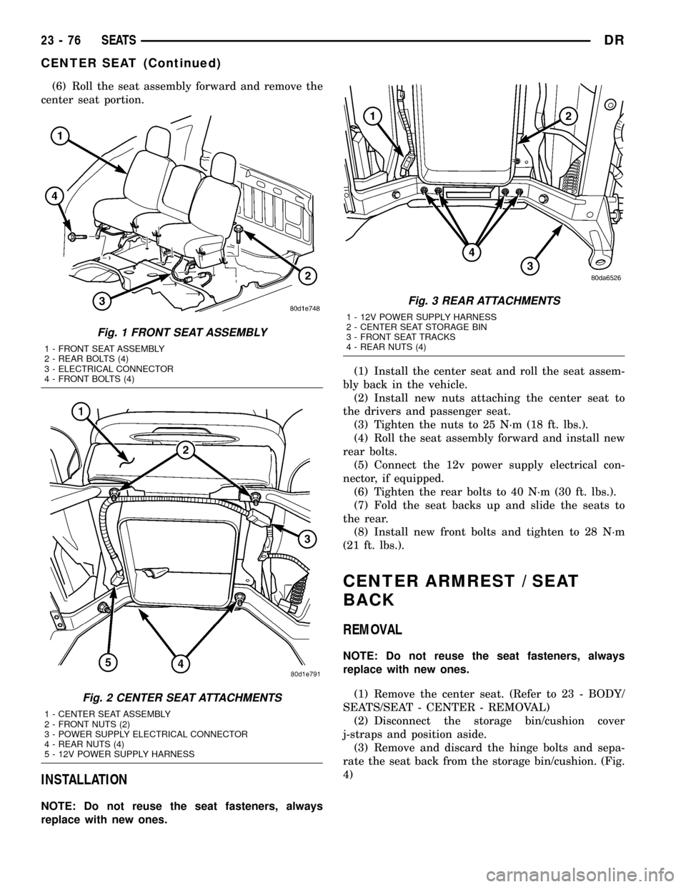
NOTE: Do not reuse the seat fasteners, always
replace with new ones.
(1) Remove and discard the front bolts. (Fig. 1)(2) Position the seats forward, remove the rear
bolts and discard.
(3) Disconnect the 12v power supply electrical con-
nector, if equipped. (Fig. 2)
(4) Fold the seat backs forward and roll the seat
assembly back in the vehicle.
(5) Remove the nuts attaching the center seat to
the drivers seat and the passenger seat and discard.
(Fig. 3)
DRSEATS 23 - 75
Page 2371 of 2627
(6) Roll the seat assembly forward and remove the
center seat portion.
INSTALLATION
NOTE: Do not reuse the seat fasteners, always
replace with new ones.(1) Install the center seat and roll the seat assem-
bly back in the vehicle.
(2) Install new nuts attaching the center seat to
the drivers and passenger seat.
(3) Tighten the nuts to 25 N´m (18 ft. lbs.).
(4) Roll the seat assembly forward and install new
rear bolts.
(5) Connect the 12v power supply electrical con-
nector, if equipped.
(6) Tighten the rear bolts to 40 N´m (30 ft. lbs.).
(7) Fold the seat backs up and slide the seats to
the rear.
(8) Install new front bolts and tighten to 28 N´m
(21 ft. lbs.).
CENTER ARMREST / SEAT
BACK
REMOVAL
NOTE: Do not reuse the seat fasteners, always
replace with new ones.
(1) Remove the center seat. (Refer to 23 - BODY/
SEATS/SEAT - CENTER - REMOVAL)
(2) Disconnect the storage bin/cushion cover
j-straps and position aside.
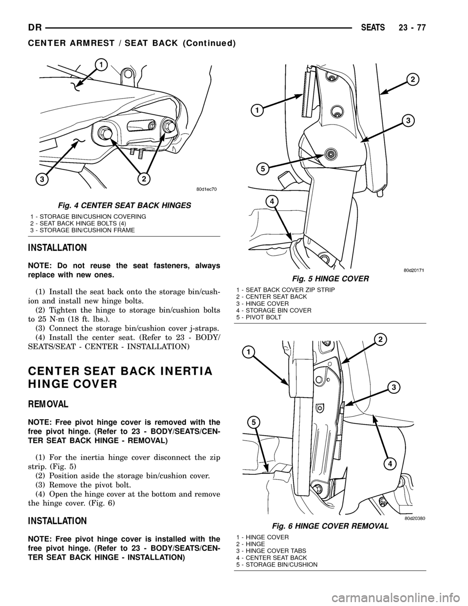
(3) Remove and discard the hinge bolts and sepa-
rate the seat back from the storage bin/cushion. (Fig.
4)
Fig. 1 FRONT SEAT ASSEMBLY
1 - FRONT SEAT ASSEMBLY
2 - REAR BOLTS (4)
3 - ELECTRICAL CONNECTOR
4 - FRONT BOLTS (4)
Fig. 2 CENTER SEAT ATTACHMENTS
1 - CENTER SEAT ASSEMBLY
2 - FRONT NUTS (2)
3 - POWER SUPPLY ELECTRICAL CONNECTOR
4 - REAR NUTS (4)
5 - 12V POWER SUPPLY HARNESS
Fig. 3 REAR ATTACHMENTS
1 - 12V POWER SUPPLY HARNESS
2 - CENTER SEAT STORAGE BIN
3 - FRONT SEAT TRACKS
4 - REAR NUTS (4)
23 - 76 SEATSDR
CENTER SEAT (Continued)
Page 2372 of 2627
INSTALLATION
NOTE: Do not reuse the seat fasteners, always
replace with new ones.
(1) Install the seat back onto the storage bin/cush-
ion and install new hinge bolts.
(2) Tighten the hinge to storage bin/cushion bolts
to 25 N´m (18 ft. lbs.).
(3) Connect the storage bin/cushion cover j-straps.
(4) Install the center seat. (Refer to 23 - BODY/
SEATS/SEAT - CENTER - INSTALLATION)
CENTER SEAT BACK INERTIA
HINGE COVER
REMOVAL
NOTE: Free pivot hinge cover is removed with the
free pivot hinge. (Refer to 23 - BODY/SEATS/CEN-
TER SEAT BACK HINGE - REMOVAL)
(1) For the inertia hinge cover disconnect the zip
strip. (Fig. 5)
(2) Position aside the storage bin/cushion cover.
(3) Remove the pivot bolt.
(4) Open the hinge cover at the bottom and remove
the hinge cover. (Fig. 6)
INSTALLATION
NOTE: Free pivot hinge cover is installed with the
free pivot hinge. (Refer to 23 - BODY/SEATS/CEN-
TER SEAT BACK HINGE - INSTALLATION)
Fig. 4 CENTER SEAT BACK HINGES
1 - STORAGE BIN/CUSHION COVERING
2 - SEAT BACK HINGE BOLTS (4)
3 - STORAGE BIN/CUSHION FRAME
Fig. 5 HINGE COVER
1 - SEAT BACK COVER ZIP STRIP
2 - CENTER SEAT BACK
3 - HINGE COVER
4 - STORAGE BIN COVER
5 - PIVOT BOLT
Fig. 6 HINGE COVER REMOVAL
1 - HINGE COVER
2 - HINGE
3 - HINGE COVER TABS
4 - CENTER SEAT BACK
5 - STORAGE BIN/CUSHION
DRSEATS 23 - 77
CENTER ARMREST / SEAT BACK (Continued)