1998 DODGE RAM 1500 Engine
[x] Cancel search: EnginePage 1483 of 2627
(7) With the engine in this position, valve lash can
be measured at the remaining rocker arms:INTAKE
3±5±6 / EXHAUST 2±4±6. Use the same method as
above for determining whether adjustment is neces-
sary, and adjust those that are found to be outside of
the limits.
(8) Install the cylinder head cover (Refer to 9 -
ENGINE/CYLINDER HEAD/CYLINDER HEAD
COVER(S) - INSTALLATION).
(9) Connect the battery negative cables.
REMOVAL - VALVE SPRINGS AND SEALS
(1) Disconnect the battery negative cables.
(2) Remove the cylinder head cover (Refer to 9 -
ENGINE/CYLINDER HEAD/CYLINDER HEAD
COVER(S) - REMOVAL).
(3) Disconnect rocker housing injector harness con-
nector. Remove all injector harness solenoid nuts.
(4) Remove injector(s) for cylinder(s) to be serviced.
Refer to Group 14 for injector removal.
(5) Remove the rocker housing.
(6) Remove the rocker arms and crossheads from
the cylinder(s) to be serviced. Mark each component
so they can be installed in their original position.
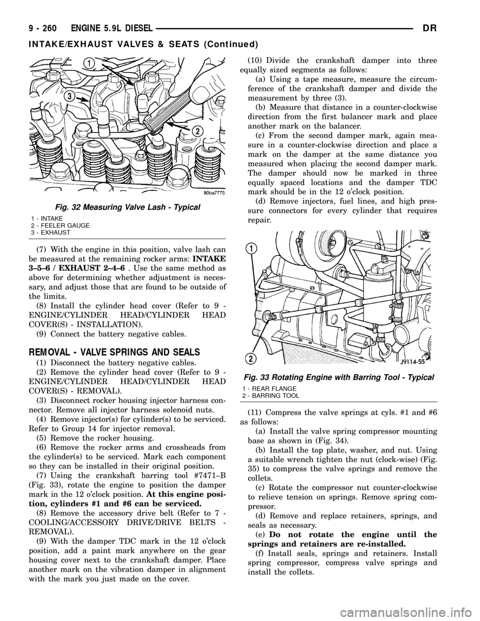
(7) Using the crankshaft barring tool #7471±B
(Fig. 33), rotate the engine to position the damper
mark in the 12 o'clock position.At this engine posi-
tion, cylinders #1 and #6 can be serviced.
(8) Remove the accessory drive belt (Refer to 7 -
COOLING/ACCESSORY DRIVE/DRIVE BELTS -
REMOVAL).
(9) With the damper TDC mark in the 12 o'clock
position, add a paint mark anywhere on the gear
housing cover next to the crankshaft damper. Place
another mark on the vibration damper in alignment
with the mark you just made on the cover.(10) Divide the crankshaft damper into three
equally sized segments as follows:
(a) Using a tape measure, measure the circum-
ference of the crankshaft damper and divide the
measurement by three (3).
(b) Measure that distance in a counter-clockwise
direction from the first balancer mark and place
another mark on the balancer.
(c) From the second damper mark, again mea-
sure in a counter-clockwise direction and place a
mark on the damper at the same distance you
measured when placing the second damper mark.
The damper should now be marked in three
equally spaced locations and the damper TDC
mark should be in the 12 o'clock position.
(d) Remove injectors, fuel lines, and high pres-
sure connectors for every cylinder that requires
repair.
(11) Compress the valve springs at cyls. #1 and #6
as follows:
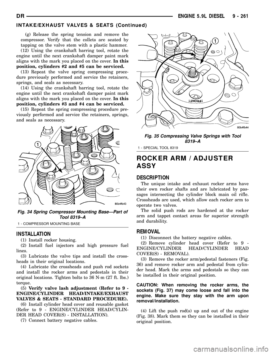
(a) Install the valve spring compressor mounting
base as shown in (Fig. 34).
(b) Install the top plate, washer, and nut. Using
a suitable wrench tighten the nut (clock-wise) (Fig.
35) to compress the valve springs and remove the
collets.
(c) Rotate the compressor nut counter-clockwise
to relieve tension on springs. Remove spring com-
pressor.
(d) Remove and replace retainers, springs, and
seals as necessary.
(e)Do not rotate the engine until the
springs and retainers are re-installed.
(f) Install seals, springs and retainers. Install
spring compressor, compress valve springs and
install the collets.
Fig. 32 Measuring Valve Lash - Typical
1 - INTAKE
2 - FEELER GAUGE
3 - EXHAUST
Fig. 33 Rotating Engine with Barring Tool - Typical
1 - REAR FLANGE
2 - BARRING TOOL
9 - 260 ENGINE 5.9L DIESELDR
INTAKE/EXHAUST VALVES & SEATS (Continued)
Page 1484 of 2627
(g) Release the spring tension and remove the
compressor. Verify that the collets are seated by
tapping on the valve stem with a plastic hammer.
(12) Using the crankshaft barring tool, rotate the
engine until the next crankshaft damper paint mark
aligns with the mark you placed on the cover.In this
position, cylinders #2 and #5 can be serviced.
(13) Repeat the valve spring compressing proce-
dure previously performed and service the retainers,
springs, and seals as necessary.
(14) Using the crankshaft barring tool, rotate the
engine until the next crankshaft damper paint mark
aligns with the mark you placed on the cover.In this
position, cylinders #3 and #4 can be serviced.
(15) Repeat the spring compressing procedure pre-
viously performed and service the retainers, springs,
and seals as necessary.
INSTALLATION
(1) Install rocker housing.
(2) Install fuel injectors and high pressure fuel
lines.
(3) Lubricate the valve tips and install the cross-
heads in their original locations.
(4) Lubricate the crossheads and push rod sockets
and install the rocker arms and pedestals in their
original locations. Tighten bolts to 36 N´m (27 ft. lbs.)
torque.
(5)Verify valve lash adjustment (Refer to 9 -
ENGINE/CYLINDER HEAD/INTAKE/EXHAUST
VALVES & SEATS - STANDARD PROCEDURE).
(6) Install cylinder head cover and reusable gasket
(Refer to 9 - ENGINE/CYLINDER HEAD/CYLIN-
DER HEAD COVER(S) - INSTALLATION).
(7) Connect battery negative cables.
ROCKER ARM / ADJUSTER
ASSY
DESCRIPTION
The unique intake and exhaust rocker arms have
their own rocker shafts and are lubricated by pas-
sages intersecting the cylinder block main oil rifle.
Crossheads are used, which allow each rocker arm to
operate two valves.
The solid push rods are hardened at the rocker
arm and tappet contact areas for superior strength
and durability.
REMOVAL
(1) Disconnect the battery negative cables.
(2) Remove cylinder head cover (Refer to 9 -
ENGINE/CYLINDER HEAD/CYLINDER HEAD
COVER(S) - REMOVAL).
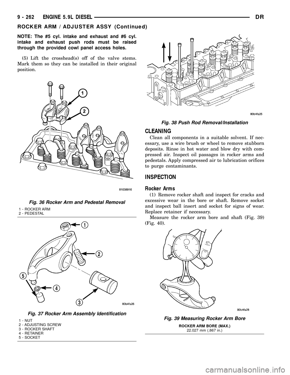
(3) Remove the rocker arm/pedestal fasteners (Fig.
36) and remove rocker arm and pedestal from cylin-
der head. Mark the arms and pedestals so they can
be installed in their original position.
CAUTION: When removing the rocker arms, the
sockets (Fig. 37) may come loose and fall into the
engine. Make sure they stay with the arm upon
removal/installation.
(4) Lift the push rod(s) up and out of the engine
(Fig. 38). Mark them so they can be installed in their
original position.
Fig. 34 Spring Compressor Mounting BaseÐPart of
Tool 8319±A
1 - COMPRESSOR MOUNTING BASE
Fig. 35 Compressing Valve Springs with Tool
8319±A
1 - SPECIAL TOOL 8319
DRENGINE 5.9L DIESEL 9 - 261
INTAKE/EXHAUST VALVES & SEATS (Continued)
Page 1485 of 2627
NOTE: The #5 cyl. intake and exhaust and #6 cyl.
intake and exhaust push rods must be raised
through the provided cowl panel access holes.
(5) Lift the crosshead(s) off of the valve stems.
Mark them so they can be installed in their original
position.
CLEANING
Clean all components in a suitable solvent. If nec-
essary, use a wire brush or wheel to remove stubborn
deposits. Rinse in hot water and blow dry with com-
pressed air. Inspect oil passages in rocker arms and
pedestals. Apply compressed air to lubrication orifices
to purge contaminants.
INSPECTION
Rocker Arms
(1) Remove rocker shaft and inspect for cracks and
excessive wear in the bore or shaft. Remove socket
and inspect ball insert and socket for signs of wear.
Replace retainer if necessary.
Measure the rocker arm bore and shaft (Fig. 39)
(Fig. 40).
Fig. 36 Rocker Arm and Pedestal Removal
1 - ROCKER ARM
2 - PEDESTAL
Fig. 37 Rocker Arm Assembly Identification
1 - NUT
2 - ADJUSTING SCREW
3 - ROCKER SHAFT
4 - RETAINER
5 - SOCKET
Fig. 38 Push Rod Removal/Installation
Fig. 39 Measuring Rocker Arm Bore
ROCKER ARM BORE (MAX.)
22.027 mm (.867 in.)
9 - 262 ENGINE 5.9L DIESELDR
ROCKER ARM / ADJUSTER ASSY (Continued)
Page 1486 of 2627
Push Rods
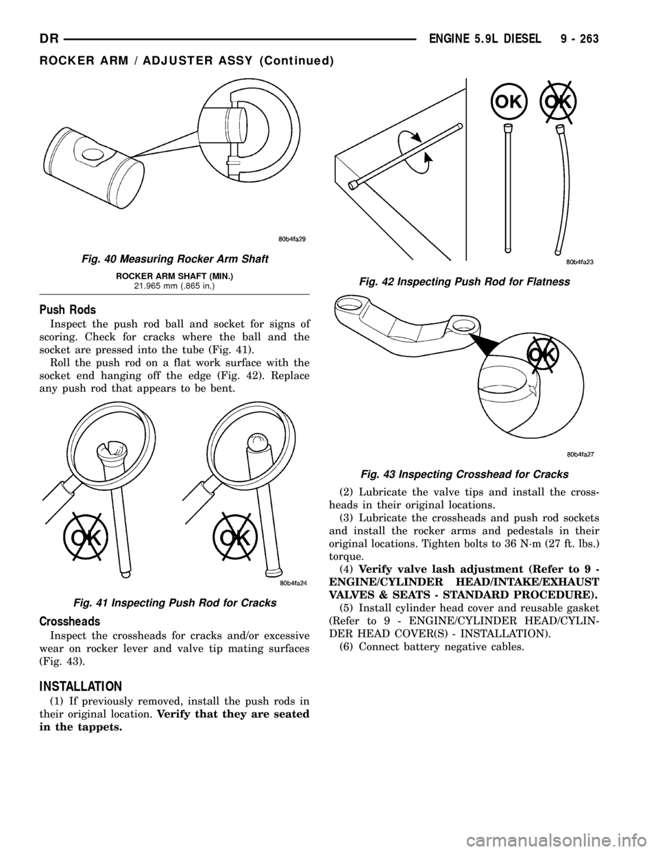
Inspect the push rod ball and socket for signs of
scoring. Check for cracks where the ball and the
socket are pressed into the tube (Fig. 41).
Roll the push rod on a flat work surface with the
socket end hanging off the edge (Fig. 42). Replace
any push rod that appears to be bent.
Crossheads
Inspect the crossheads for cracks and/or excessive
wear on rocker lever and valve tip mating surfaces
(Fig. 43).
INSTALLATION
(1) If previously removed, install the push rods in
their original location.Verify that they are seated
in the tappets.(2) Lubricate the valve tips and install the cross-
heads in their original locations.
(3) Lubricate the crossheads and push rod sockets
and install the rocker arms and pedestals in their
original locations. Tighten bolts to 36 N´m (27 ft. lbs.)
torque.
(4)Verify valve lash adjustment (Refer to 9 -
ENGINE/CYLINDER HEAD/INTAKE/EXHAUST
VALVES & SEATS - STANDARD PROCEDURE).
(5) Install cylinder head cover and reusable gasket
(Refer to 9 - ENGINE/CYLINDER HEAD/CYLIN-
DER HEAD COVER(S) - INSTALLATION).
(6) Connect battery negative cables.
Fig. 40 Measuring Rocker Arm Shaft
ROCKER ARM SHAFT (MIN.)
21.965 mm (.865 in.)
Fig. 41 Inspecting Push Rod for Cracks
Fig. 42 Inspecting Push Rod for Flatness
Fig. 43 Inspecting Crosshead for Cracks
DRENGINE 5.9L DIESEL 9 - 263
ROCKER ARM / ADJUSTER ASSY (Continued)
Page 1487 of 2627
ENGINE BLOCK
STANDARD PROCEDURE
STANDARD PROCEDURE - CYLINDER BLOCK
REFACING
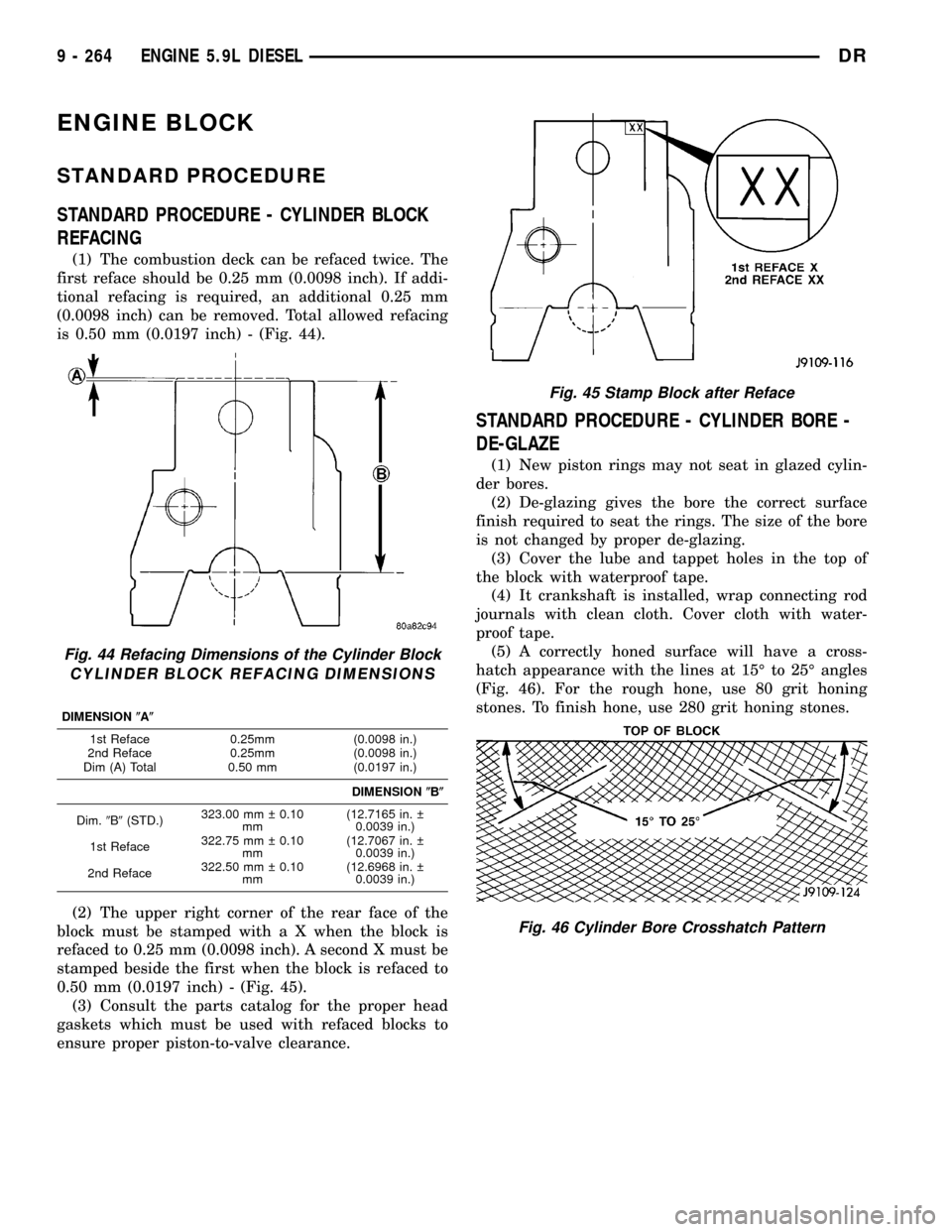
(1) The combustion deck can be refaced twice. The
first reface should be 0.25 mm (0.0098 inch). If addi-
tional refacing is required, an additional 0.25 mm
(0.0098 inch) can be removed. Total allowed refacing
is 0.50 mm (0.0197 inch) - (Fig. 44).
(2) The upper right corner of the rear face of the
block must be stamped with a X when the block is
refaced to 0.25 mm (0.0098 inch). A second X must be
stamped beside the first when the block is refaced to
0.50 mm (0.0197 inch) - (Fig. 45).
(3) Consult the parts catalog for the proper head
gaskets which must be used with refaced blocks to
ensure proper piston-to-valve clearance.
STANDARD PROCEDURE - CYLINDER BORE -
DE-GLAZE
(1) New piston rings may not seat in glazed cylin-
der bores.
(2) De-glazing gives the bore the correct surface
finish required to seat the rings. The size of the bore
is not changed by proper de-glazing.
(3) Cover the lube and tappet holes in the top of
the block with waterproof tape.
(4) It crankshaft is installed, wrap connecting rod
journals with clean cloth. Cover cloth with water-
proof tape.
(5) A correctly honed surface will have a cross-
hatch appearance with the lines at 15É to 25É angles
(Fig. 46). For the rough hone, use 80 grit honing
stones. To finish hone, use 280 grit honing stones.
Fig. 44 Refacing Dimensions of the Cylinder Block
CYLINDER BLOCK REFACING DIMENSIONS
DIMENSION(A(
1st Reface 0.25mm (0.0098 in.)
2nd Reface 0.25mm (0.0098 in.)
Dim (A) Total 0.50 mm (0.0197 in.)
DIMENSION(B(
Dim.9B9(STD.)323.00 mm 0.10
mm(12.7165 in.
0.0039 in.)
1st Reface322.75 mm 0.10
mm(12.7067 in.
0.0039 in.)
2nd Reface322.50 mm 0.10
mm(12.6968 in.
0.0039 in.)
Fig. 45 Stamp Block after Reface
Fig. 46 Cylinder Bore Crosshatch Pattern
9 - 264 ENGINE 5.9L DIESELDR
Page 1488 of 2627
(6) Use a drill, a fine grit Flex-hone and a mixture
of equal parts of mineral spirits and SAE 30W engine
oil to de-glaze the bores.
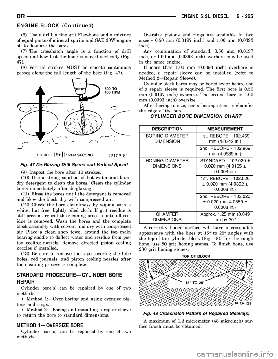
(7) The crosshatch angle is a function of drill
speed and how fast the hone is moved vertically (Fig.
47).
(8) Vertical strokes MUST be smooth continuous
passes along the full length of the bore (Fig. 47).
(9) Inspect the bore after 10 strokes.
(10) Use a strong solution of hot water and laun-
dry detergent to clean the bores. Clean the cylinder
bores immediately after de-glazing.
(11) Rinse the bores until the detergent is removed
and blow the block dry with compressed air.
(12) Check the bore cleanliness by wiping with a
white, lint free, lightly oiled cloth. If grit residue is
still present, repeat the cleaning process until all res-
idue is removed. Wash the bores and the complete
block assembly with solvent and dry with compressed
air. Place a clean shop towel around the top main
bearing saddle to deflect water and residue from pis-
ton cooling nozzels. Remove directed piston cooling
nozzles if installed.
(13) Be sure to remove the tape covering the lube
holes, rod journals, and piston cooling nozzles after
the cleaning process is complete.
STANDARD PROCEDUREÐCYLINDER BORE
REPAIR
Cylinder bore(s) can be repaired by one of two
methods:
²Method 1:ÐOver boring and using oversize pis-
tons and rings.
²Method 2:ÐBoring and installing a repair sleeve
to return the bore to standard dimensions.
METHOD 1ÐOVERSIZE BORE
Cylinder bore(s) can be repaired by one of two
methods:Oversize pistons and rings are available in two
sizes - 0.50 mm (0.0197 inch) and 1.00 mm (0.0393
inch).
Any combination of standard, 0.50 mm (0.0197
inch) or 1.00 mm (0.0393 inch) overbore may be used
in the same engine.
If more than 1.00 mm (0.0393 inch) overbore is
needed, a repair sleeve can be installed (refer to
Method 2ÐRepair Sleeve).
Cylinder block bores may be bored twice before use
of a repair sleeve is required. The first bore is 0.50
mm (0.0197 inch) oversize. The second bore is 1.00
mm (0.0393 inch) oversize.
After boring to size, use a honing stone to chamfer
the edge of the bore.
CYLINDER BORE DIMENSION CHART
DESCRIPTION MEASUREMENT
BORING DIAMETER
DIMENSION1st. REBORE - 102.469
mm (4.0342 in.)
2nd. REBORE - 102.969
mm (4.0539 in.)
HONING DIAMETER
DIMENSIONSSTANDARD - 102.020
0.020 mm (4.0165
0.0008 in.)
1st. REBORE - 102.520
0.020 mm (4.0362
0.0008 in.)
2nd. REBORE - 103.020
0.020 mm 4.0559
0.0008 in.)
CHAMFER
DIMENSIONSApprox. 1.25 mm (0.049
in.) by 30É
A correctly honed surface will have a crosshatch
appearance with the lines at 15É to 25É angles with
the top of the cylinder block (Fig. 48). For the rough
hone, use 80 grit honing stones. To finish hone, use
280 grit honing stones.
A maximum of 1.2 micrometer (48 microinch) sur-
face finish must be obtained.
Fig. 47 De-Glazing Drill Speed and Vertical Speed
Fig. 48 Crosshatch Pattern of Repaired Sleeve(s)
DRENGINE 5.9L DIESEL 9 - 265
ENGINE BLOCK (Continued)
Page 1489 of 2627
After finish honing is complete, immediately clean
the cylinder bores with a strong solution of laundry
detergent and hot water.
After rinsing, blow the block dry.
Check the bore cleanliness by wiping with a white,
lint-free, lightly- oiled cloth. There should be no grit
residue present.
If the block is not to be used right away, coat it
with a rust- preventing compound.
METHOD 2ÐREPAIR SLEEVE
If more than a 1.00 mm (0.03937 inch) diameter
oversize bore is required, the block must be bored
and a repair sleeve installed.
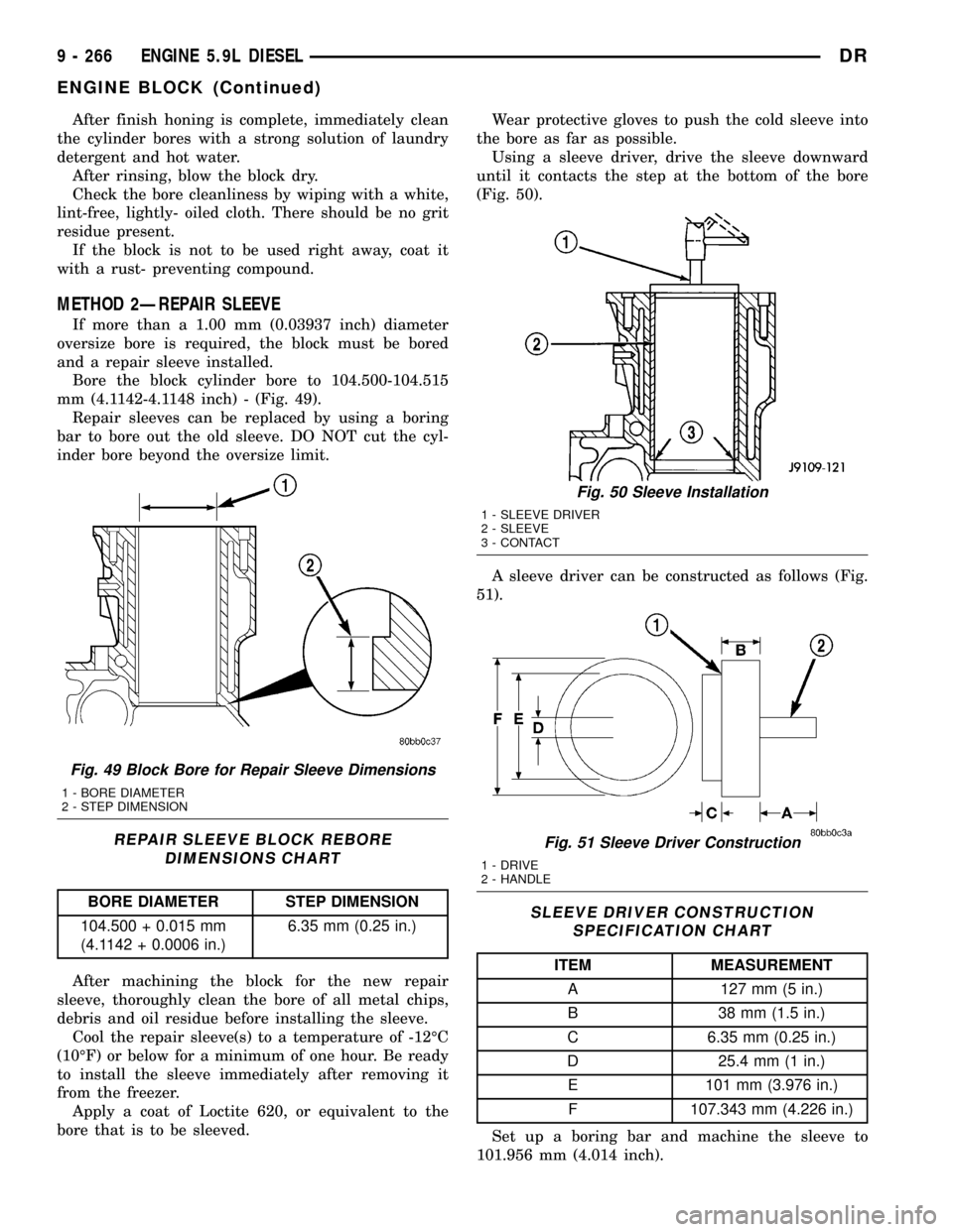
Bore the block cylinder bore to 104.500-104.515
mm (4.1142-4.1148 inch) - (Fig. 49).
Repair sleeves can be replaced by using a boring
bar to bore out the old sleeve. DO NOT cut the cyl-
inder bore beyond the oversize limit.
REPAIR SLEEVE BLOCK REBORE
DIMENSIONS CHART
BORE DIAMETER STEP DIMENSION
104.500 + 0.015 mm
(4.1142 + 0.0006 in.)6.35 mm (0.25 in.)
After machining the block for the new repair
sleeve, thoroughly clean the bore of all metal chips,
debris and oil residue before installing the sleeve.
Cool the repair sleeve(s) to a temperature of -12ÉC
(10ÉF) or below for a minimum of one hour. Be ready
to install the sleeve immediately after removing it
from the freezer.
Apply a coat of Loctite 620, or equivalent to the
bore that is to be sleeved.Wear protective gloves to push the cold sleeve into
the bore as far as possible.
Using a sleeve driver, drive the sleeve downward
until it contacts the step at the bottom of the bore
(Fig. 50).
A sleeve driver can be constructed as follows (Fig.
51).SLEEVE DRIVER CONSTRUCTION
SPECIFICATION CHART
ITEM MEASUREMENT
A 127 mm (5 in.)
B 38 mm (1.5 in.)
C 6.35 mm (0.25 in.)
D 25.4 mm (1 in.)
E 101 mm (3.976 in.)
F 107.343 mm (4.226 in.)
Set up a boring bar and machine the sleeve to
101.956 mm (4.014 inch).
Fig. 49 Block Bore for Repair Sleeve Dimensions
1 - BORE DIAMETER
2 - STEP DIMENSION
Fig. 50 Sleeve Installation
1 - SLEEVE DRIVER
2 - SLEEVE
3 - CONTACT
Fig. 51 Sleeve Driver Construction
1 - DRIVE
2 - HANDLE
9 - 266 ENGINE 5.9L DIESELDR
ENGINE BLOCK (Continued)
Page 1490 of 2627
After removing the boring bar, use a honing stone
to chamfer the corner of the repair sleeve(s).
SLEEVE MACHINING DIMENSIONS CHART
ITEM MEASUREMENT
SLEEVE PROTRUSION MIN. - FLUSH WITH
BLOCK
MAX. - 0.050 mm
(0.0019 in.)
SLEEVE DIAMETER 101.956 mm (4.014 in.)
SLEEVE CHAMFER APPROX. 1.25 mm
(0.049 in.) by 15É
A correctly honed surface will have a crosshatch
appearance with the lines at 15É to 25É angles with
the top of the cylinder block. For the rough hone, use
80 grit honing stones. To finish hone, use 280 grit
honing stones.
Finished bore inside dimension is 102.020 0.020
mm (4.0165 0.0008 inch).
A maximum of 1.2 micrometer (48 microinch) sur-
face finish must be obtained.
After finish honing is complete, immediately clean
the cylinder bores with a strong solution of laundry
detergent and hot water.
After rinsing, blow the block dry with compressed
air.
Wipe the bore with a white, lint-free, lightly oiled
cloth. Make sure there is no grit residue present.
Apply a rust-preventing compound if the block will
not be used immediately.
A standard diameter piston and a piston ring set
must be used with a sleeved cylinder bore.
STANDARD PROCEDUREÐCAM BORE REPAIR
For standard bushings, not oversized, maximum
front and rear cam bushing bore diameter is 59.248
mm. (2.3326 in.). DO NOT bore the intermediate cam
bore to the front cam bore oversize dimensions. Max-
imum front and rear camshaft bushing installed
diameter is 54.147 mm. (2.1318 in.). Minimum
installed diameter is 54.083 mm. (2.1293 in.). Maxi-
mum intermediate camshaft bore diameter is 54.164
mm. (2.1324 in.).
A surface finish of 2.3 micrometers (92 microinch)
must be maintained. Not more than 20% of an area
of any one bore may be 3.2 micrometers (126 micro-
inch).
Camshaft bores can be repaired individually. It is
not necessary to repair undamaged cam bores in
order to repair individually damaged cam bores. The
standard front bushing cannot be used to repair
intermediate bores.Install all cam bushings flush or below the front
and rear cam bore surface. The front camshaft bush-
ing should be installed flush with front face of block.
The rear camshaft bushing should be installed flush
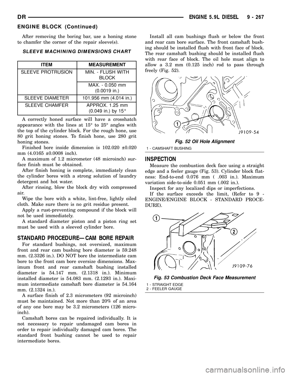
with rear face of block. The oil hole must align to
allow a 3.2 mm (0.125 inch) rod to pass through
freely (Fig. 52).
INSPECTION
Measure the combustion deck face using a straight
edge and a feeler gauge (Fig. 53). Cylinder block flat-
ness: End-to-end 0.076 mm ( .003 in.). Maximum
variation side-to-side 0.051 mm (.002 in.).
Inspect for any localized dips or imperfections.
If the surface exceeds the limit, (Refer to 9 -
ENGINE/ENGINE BLOCK - STANDARD PROCE-
DURE).
Fig. 52 Oil Hole Alignment
1 - CAMSHAFT BUSHING
Fig. 53 Combustion Deck Face Measurement
1 - STRAIGHT EDGE
2 - FEELER GAUGE
DRENGINE 5.9L DIESEL 9 - 267
ENGINE BLOCK (Continued)