1998 DODGE RAM 1500 Engine
[x] Cancel search: EnginePage 1491 of 2627
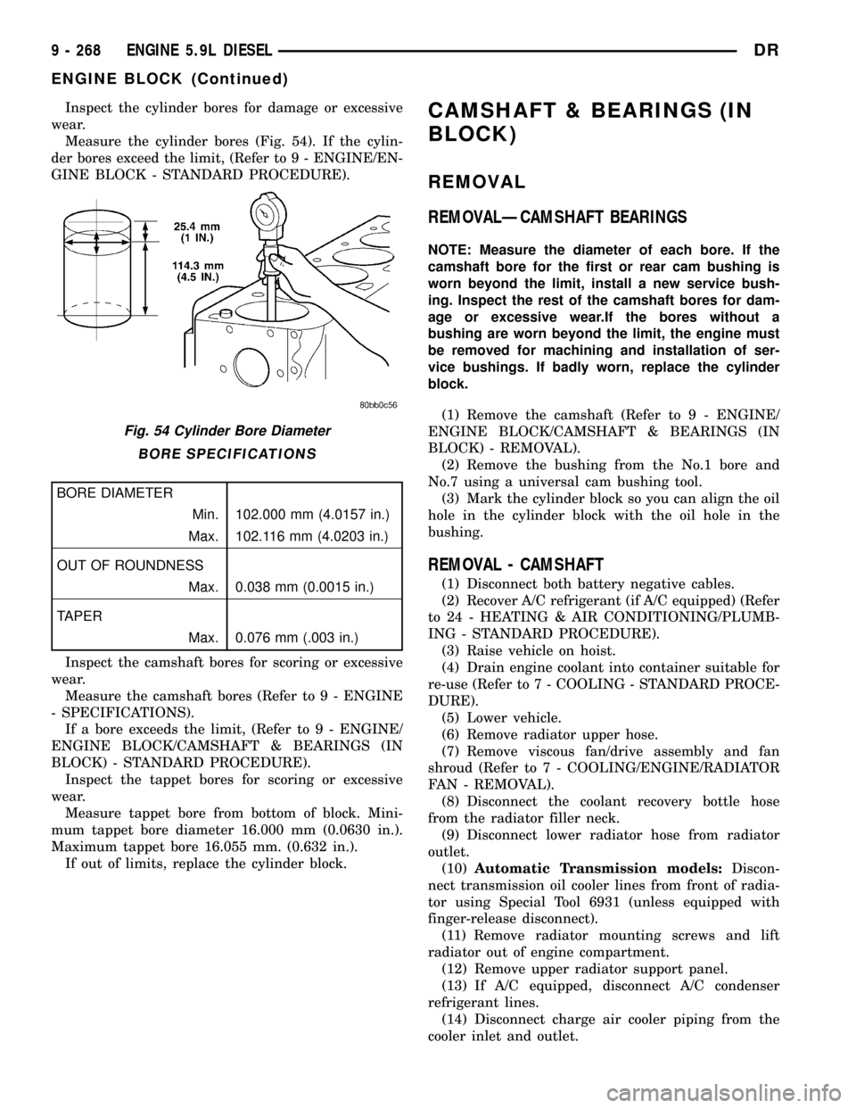
Inspect the cylinder bores for damage or excessive
wear.
Measure the cylinder bores (Fig. 54). If the cylin-
der bores exceed the limit, (Refer to 9 - ENGINE/EN-
GINE BLOCK - STANDARD PROCEDURE).
BORE SPECIFICATIONS
BORE DIAMETER
Min. 102.000 mm (4.0157 in.)
Max. 102.116 mm (4.0203 in.)
OUT OF ROUNDNESS
Max. 0.038 mm (0.0015 in.)
TAPER
Max. 0.076 mm (.003 in.)
Inspect the camshaft bores for scoring or excessive
wear.
Measure the camshaft bores (Refer to 9 - ENGINE
- SPECIFICATIONS).
If a bore exceeds the limit, (Refer to 9 - ENGINE/
ENGINE BLOCK/CAMSHAFT & BEARINGS (IN
BLOCK) - STANDARD PROCEDURE).
Inspect the tappet bores for scoring or excessive
wear.
Measure tappet bore from bottom of block. Mini-
mum tappet bore diameter 16.000 mm (0.0630 in.).
Maximum tappet bore 16.055 mm. (0.632 in.).
If out of limits, replace the cylinder block.
CAMSHAFT & BEARINGS (IN
BLOCK)
REMOVAL
REMOVALÐCAMSHAFT BEARINGS
NOTE: Measure the diameter of each bore. If the
camshaft bore for the first or rear cam bushing is
worn beyond the limit, install a new service bush-
ing. Inspect the rest of the camshaft bores for dam-
age or excessive wear.If the bores without a
bushing are worn beyond the limit, the engine must
be removed for machining and installation of ser-
vice bushings. If badly worn, replace the cylinder
block.
(1) Remove the camshaft (Refer to 9 - ENGINE/
ENGINE BLOCK/CAMSHAFT & BEARINGS (IN
BLOCK) - REMOVAL).
(2) Remove the bushing from the No.1 bore and
No.7 using a universal cam bushing tool.
(3) Mark the cylinder block so you can align the oil
hole in the cylinder block with the oil hole in the
bushing.
REMOVAL - CAMSHAFT
(1) Disconnect both battery negative cables.
(2) Recover A/C refrigerant (if A/C equipped) (Refer
to 24 - HEATING & AIR CONDITIONING/PLUMB-
ING - STANDARD PROCEDURE).
(3) Raise vehicle on hoist.
(4) Drain engine coolant into container suitable for
re-use (Refer to 7 - COOLING - STANDARD PROCE-
DURE).
(5) Lower vehicle.
(6) Remove radiator upper hose.
(7) Remove viscous fan/drive assembly and fan
shroud (Refer to 7 - COOLING/ENGINE/RADIATOR
FAN - REMOVAL).
(8) Disconnect the coolant recovery bottle hose
from the radiator filler neck.
(9) Disconnect lower radiator hose from radiator
outlet.
(10)Automatic Transmission models:Discon-
nect transmission oil cooler lines from front of radia-
tor using Special Tool 6931 (unless equipped with
finger-release disconnect).
(11) Remove radiator mounting screws and lift
radiator out of engine compartment.
(12) Remove upper radiator support panel.
(13) If A/C equipped, disconnect A/C condenser
refrigerant lines.
(14) Disconnect charge air cooler piping from the
cooler inlet and outlet.
Fig. 54 Cylinder Bore Diameter
9 - 268 ENGINE 5.9L DIESELDR
ENGINE BLOCK (Continued)
Page 1492 of 2627
(15) Remove the two charge air cooler mounting
bolts.
(16) Remove charge air cooler (and A/C condenser
if equipped) from vehicle.
(17) Remove accessory drive belt (Refer to 7 -
COOLING/ACCESSORY DRIVE/DRIVE BELTS -
REMOVAL).
(18) Remove accessory drive belt tensioner.
(19) Remove the fan support/hub assembly.
(20) Remove crankshaft damper and speed indica-
tor ring (Refer to 9 - ENGINE/ENGINE BLOCK/VI-
BRATION DAMPER - REMOVAL).
(21) Remove the gear cover-to-housing bolts and
gently pry the cover away from the housing, taking
care not to mar the sealing surfaces. Remove dust
seal with cover.
(22) Using Special Tool 7471±B Crankshaft Bar-
ring Tool, rotate the crankshaft to align the timing
marks on the crankshaft and the camshaft gears.
(23) Remove the cylinder head cover (Refer to 9 -
ENGINE/CYLINDER HEAD/CYLINDER HEAD
COVER(S) - REMOVAL).
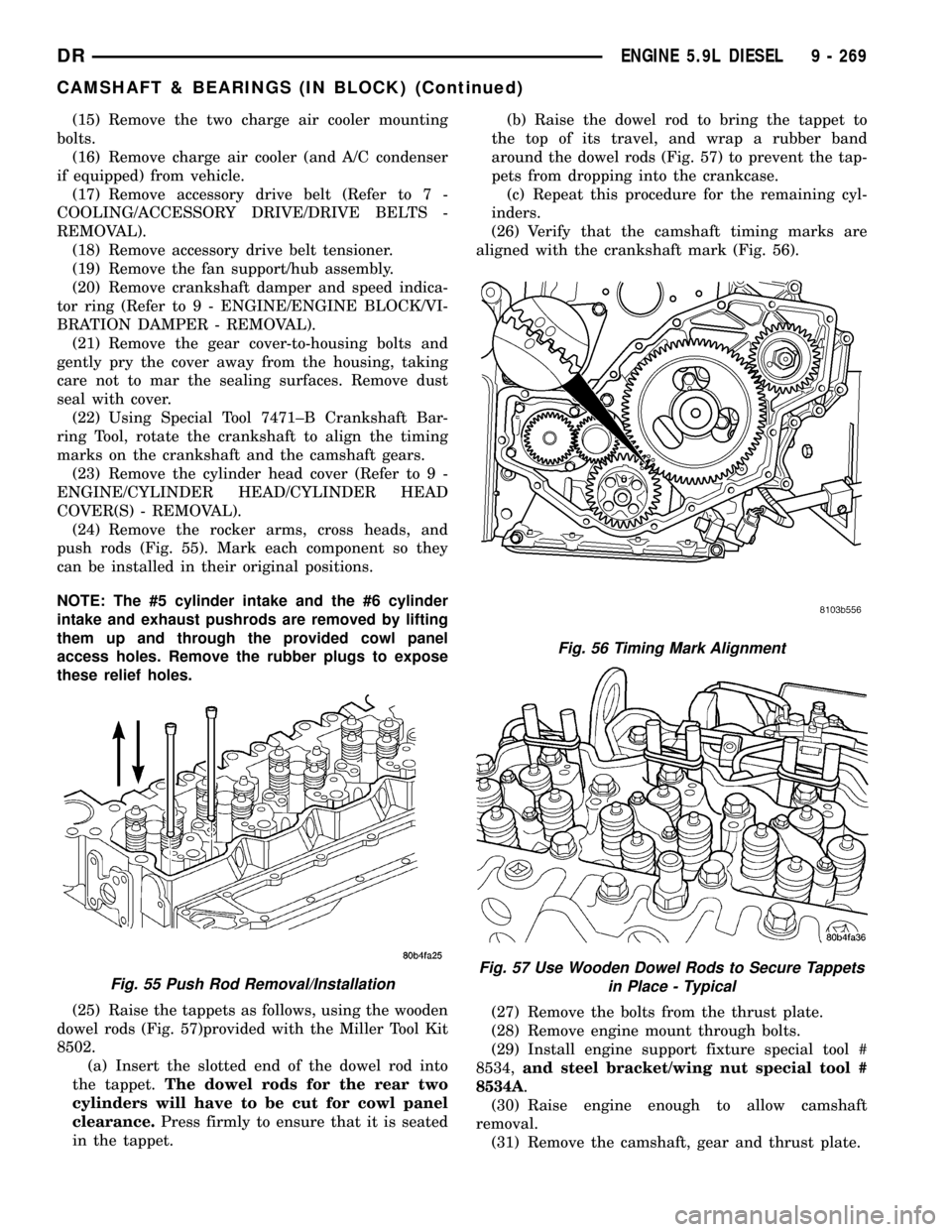
(24) Remove the rocker arms, cross heads, and
push rods (Fig. 55). Mark each component so they
can be installed in their original positions.
NOTE: The #5 cylinder intake and the #6 cylinder
intake and exhaust pushrods are removed by lifting
them up and through the provided cowl panel
access holes. Remove the rubber plugs to expose
these relief holes.
(25) Raise the tappets as follows, using the wooden
dowel rods (Fig. 57)provided with the Miller Tool Kit
8502.
(a) Insert the slotted end of the dowel rod into
the tappet.The dowel rods for the rear two
cylinders will have to be cut for cowl panel
clearance.Press firmly to ensure that it is seated
in the tappet.(b) Raise the dowel rod to bring the tappet to
the top of its travel, and wrap a rubber band
around the dowel rods (Fig. 57) to prevent the tap-
pets from dropping into the crankcase.
(c) Repeat this procedure for the remaining cyl-
inders.
(26) Verify that the camshaft timing marks are
aligned with the crankshaft mark (Fig. 56).
(27) Remove the bolts from the thrust plate.
(28) Remove engine mount through bolts.
(29) Install engine support fixture special tool #
8534,and steel bracket/wing nut special tool #
8534A.
(30) Raise engine enough to allow camshaft
removal.
(31) Remove the camshaft, gear and thrust plate.
Fig. 55 Push Rod Removal/Installation
Fig. 56 Timing Mark Alignment
Fig. 57 Use Wooden Dowel Rods to Secure Tappets
in Place - Typical
DRENGINE 5.9L DIESEL 9 - 269
CAMSHAFT & BEARINGS (IN BLOCK) (Continued)
Page 1493 of 2627
INSPECTION
Camshaft
(1) Inspect the valve lobes and bearing journals for
cracks, pitting, scoring, or generally excessive wear.
Replace any camshaft that exceeds the allowable lim-
its.
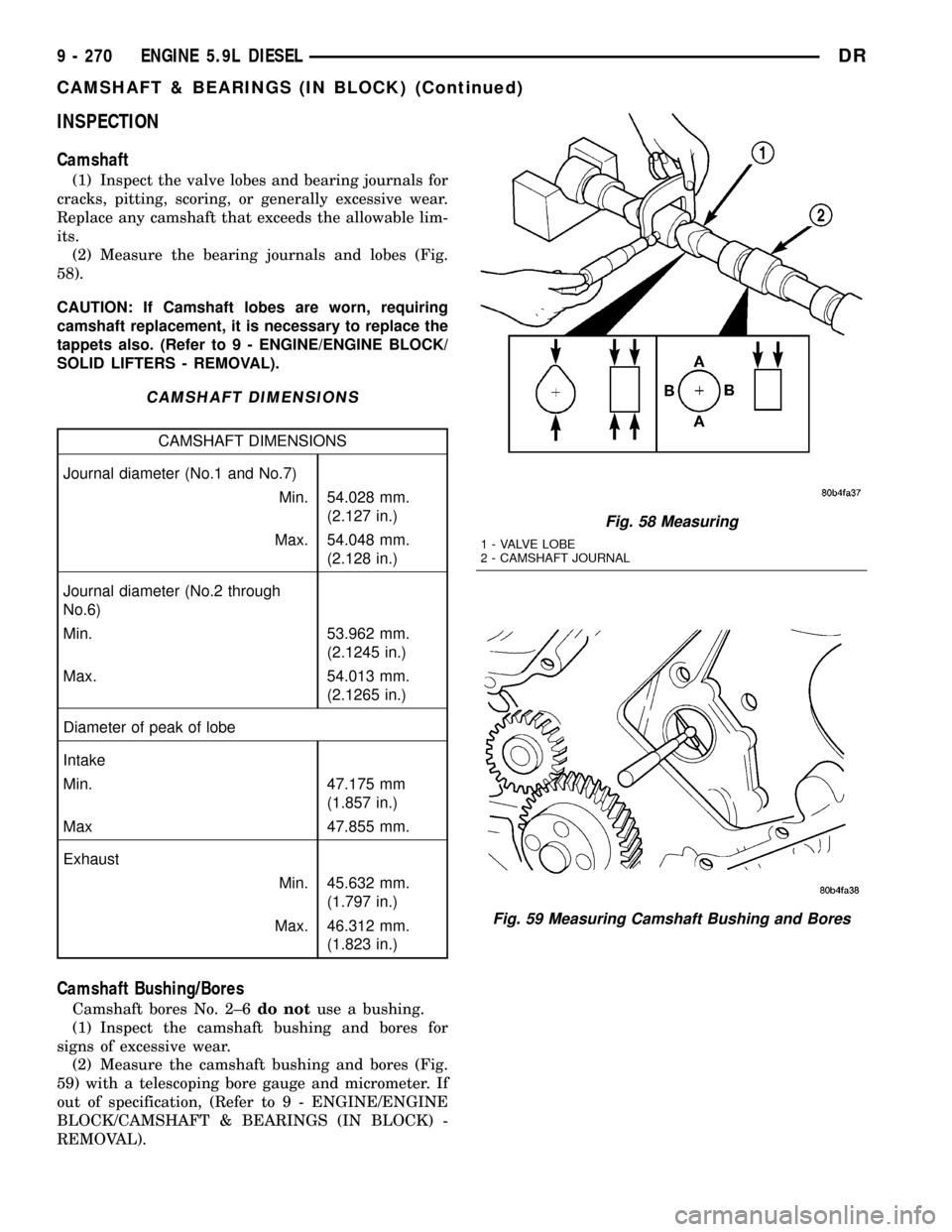
(2) Measure the bearing journals and lobes (Fig.
58).
CAUTION: If Camshaft lobes are worn, requiring
camshaft replacement, it is necessary to replace the
tappets also. (Refer to 9 - ENGINE/ENGINE BLOCK/
SOLID LIFTERS - REMOVAL).
CAMSHAFT DIMENSIONS
CAMSHAFT DIMENSIONS
Journal diameter (No.1 and No.7)
Min. 54.028 mm.
(2.127 in.)
Max. 54.048 mm.
(2.128 in.)
Journal diameter (No.2 through
No.6)
Min. 53.962 mm.
(2.1245 in.)
Max. 54.013 mm.
(2.1265 in.)
Diameter of peak of lobe
Intake
Min. 47.175 mm
(1.857 in.)
Max 47.855 mm.
Exhaust
Min. 45.632 mm.
(1.797 in.)
Max. 46.312 mm.
(1.823 in.)
Camshaft Bushing/Bores
Camshaft bores No. 2±6do notuse a bushing.
(1) Inspect the camshaft bushing and bores for
signs of excessive wear.
(2) Measure the camshaft bushing and bores (Fig.
59) with a telescoping bore gauge and micrometer. If
out of specification, (Refer to 9 - ENGINE/ENGINE
BLOCK/CAMSHAFT & BEARINGS (IN BLOCK) -
REMOVAL).
Fig. 59 Measuring Camshaft Bushing and Bores
Fig. 58 Measuring
1 - VALVE LOBE
2 - CAMSHAFT JOURNAL
9 - 270 ENGINE 5.9L DIESELDR
CAMSHAFT & BEARINGS (IN BLOCK) (Continued)
Page 1494 of 2627
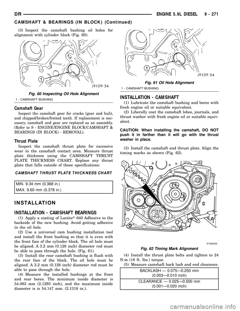
(3) Inspect the camshaft bushing oil holes for
alignment with cylinder block (Fig. 60).
Camshaft Gear
Inspect the camshaft gear for cracks (gear and hub),
and chipped/broken/fretted teeth. If replacement is nec-
essary, camshaft and gear are replaced as an assembly.
(Refer to 9 - ENGINE/ENGINE BLOCK/CAMSHAFT &
BEARINGS (IN BLOCK) - REMOVAL).
Thrust Plate
Inspect the camshaft thrust plate for excessive
wear in the camshaft contact area. Measure thrust
plate thickness using the CAMSHAFT THRUST
PLATE THICKNESS CHART. Replace any thrust
plate that falls outside of these specifications:
CAMSHAFT THRUST PLATE THICKNESS CHART
MIN. 9.34 mm (0.368 in.)
MAX. 9.60 mm (0.378 in.)
INSTALLATION
INSTALLATION - CAMSHAFT BEARINGS
(1) Apply a coating of Loctitet640 Adhesive to the
backside of the new bushing. Avoid getting adhesive
in the oil hole.
(2) Use a universal cam bushing installation tool
and install the front bushing so that it is even with
the front face of the cylinder block. The oil hole must
be aligned. A 3.2 mm (0.128 inch) diameter rod must
be able to pass through the hole. (Fig. 61).
(3) Install the rear camshaft bushing is flush with
the rear face of the block. The oil hole must be
aligned. A 3.2 mm (0.128 inch) diameter rod must be
able to pass through the hole.
(4) Measure the installed bushings at the front
and rear bores. The minimum inside diameter is
54.083 mm (2.1293 inch), and the maximum inside
diameter is is 54.147 mm. (2.1318 in.).
INSTALLATION - CAMSHAFT
(1) Lubricate the camshaft bushing and bores with
fresh engine oil or suitable equivalent.
(2) Liberally coat the camshaft lobes, journals, and
thrust washer with fresh engine oil or suitable equiv-
alent.
CAUTION: When installing the camshaft, DO NOT
push it in farther than it will go with the thrust
washer in place.
(3) Install the camshaft and thrust plate. Align the
timing marks as shown (Fig. 62).
(4) Install the thrust plate bolts and tighten to 24
N´m (18 ft. lbs.) torque.
(5) Measure camshaft back lash and end clearance.
BACKLASH Ð 0.075Ð0.250 mm
(0.003Ð0.010 inch)
CLEARANCE Ð 0.025Ð0.500 mm
(0.001Ð0.020 inch)
Fig. 60 Inspecting Oil Hole Alignment
1 - CAMSHAFT BUSHING
Fig. 61 Oil Hole Alignment
1 - CAMSHAFT BUSHING
Fig. 62 Timing Mark Alignment
DRENGINE 5.9L DIESEL 9 - 271
CAMSHAFT & BEARINGS (IN BLOCK) (Continued)
Page 1495 of 2627
(6) Remove the wooden dowel rods and rubber
bands from the tappets.
(7) Lubricate the push rods with engine oil and
install in their original location.Verify that they
are seated in the tappets.
(8) Lubricate the valve tips with engine oil and
install the crossheads in their original locations.
(9) Lubricate the crossheads and push rod sockets
with engine oil and install the rocker arms and ped-
estals in their original locations. Tighten bolts to 36
N´m (27 ft. lbs.) torque.
(10)Verify valve lash adjustment (Refer to 9 -
ENGINE/CYLINDER HEAD/INTAKE/EXHAUST
VALVES & SEATS - STANDARD PROCEDURE).
(11) Install the cylinder head cover and reusable
gasket (Refer to 9 - ENGINE/CYLINDER HEAD/
CYLINDER HEAD COVER(S) - INSTALLATION).
(12) Install gear housing cover (Refer to 9 -
ENGINE/VALVE TIMING/GEAR HOUSING COVER
- INSTALLATION). Install front crankshaft dust
seal.
(13) Install the crankshaft damper with the speed
indicator ring (Refer to 9 - ENGINE/ENGINE
BLOCK/VIBRATION DAMPER - INSTALLATION).
(14) Install the fan support/hub assembly Refer to
(Refer to 7 - COOLING/ENGINE/RADIATOR FAN -
INSTALLATION).
(15) Install the power steering pump.
(16) Install accessory drive belt tensioner. Torque
bolt to 43 Nm (32 ft. lbs.).
(17) Install the accessory drive belt (Refer to 7 -
COOLING/ACCESSORY DRIVE/DRIVE BELTS -
INSTALLATION).
(18) Install the charge air cooler (with a/c con-
denser and auxiliary transmission oil cooler, if
equipped) and tighten the mounting bolts to 2 N´m
(17 in. lbs.) torque.
(19) Connect charge air cooler inlet and outlet
pipes. Tighten clamps to 11 N´m (95 in. lbs.) torque.
(20) Install the radiator upper support panel.
(21) Close radiator petcock and lower the radiator
into the engine compartment. Tighten the mounting
bolts to 11 N´m (95 in. lbs.) torque.
(22) Raise vehicle on hoist.
(23) Connect radiator lower hose and install
clamp.
(24) Connect transmission auxiliary oil cooler lines
(if equipped).
(25) Lower vehicle.
(26) Install the fan shroud and tighten the mount-
ing screws to 6 N´m (50 in. lbs.) torque.
(27) Install the electronically controlled viscous
fan/drive assembly. Connect harness connector.(Refer
to 7 - COOLING/ENGINE/RADIATOR FAN -
INSTALLATION).(28) Install the coolant recovery and windshield
washer fluid reservoirs to the fan shroud.
(29) Connect the coolant recovery hose to the radi-
ator filler neck.
(30) Add engine coolant (Refer to 7 - COOLING -
STANDARD PROCEDURE).
(31) Charge A/C system with refrigerant (if A/C
equipped) (Refer to 24 - HEATING & AIR CONDI-
TIONING/PLUMBING - STANDARD PROCEDURE).
(32) Connect the battery negative cables.
(33) Start engine and check for engine oil and cool-
ant leaks.
CONNECTING ROD BEARINGS
STANDARD PROCEDURE - CONNECTING ROD
BEARING AND CRANKSHAFT JOURNAL
CLEARANCE
(1) Measure the connecting rod bore with bearings
removedand the bolts tightened to 100 N´m (73 ft.
lbs.) torque..
(2) Measure the connecting rod bore with the bear-
ingsinstalledand the bolts tightened to 100 N´m
(73 ft. lbs.) torque.
Measure within 20É arc from each side of the part-
ing line. Also measure 90É from parting line.
Record the smallest and largest diameter.
Measure the diameter of the rod journal at the
location shown (Fig. 63). Calculate the average diam-
eter for each side of the journal.
Determine minimum bearing clearance by calculat-
ing the differance between the smallest connecting
rod bore diameter with the bearing installed and the
average diameter for each side of the crankshaft jour-
nal.
Determine the maximum bearing clearance by cal-
culating the difference between the largest connect-
ing rod bore diameter and the average diameter with
the bearing installed for each side of the crankshaft
journal.
DESCRIPTION MEASUREMENT
CONNECTING ROD
BORE, BEARINGS
REMOVEDMIN. 72.99 mm (2.874
in.)
MAX. 73.01 mm (2.875
in.)
CONNECTING ROD
BORE, BEARINGS
INSTALLEDMIN. 69.05 mm (2.719
in.)
MAX. 69.10 mm (2.720
in.)
9 - 272 ENGINE 5.9L DIESELDR
CAMSHAFT & BEARINGS (IN BLOCK) (Continued)
Page 1496 of 2627
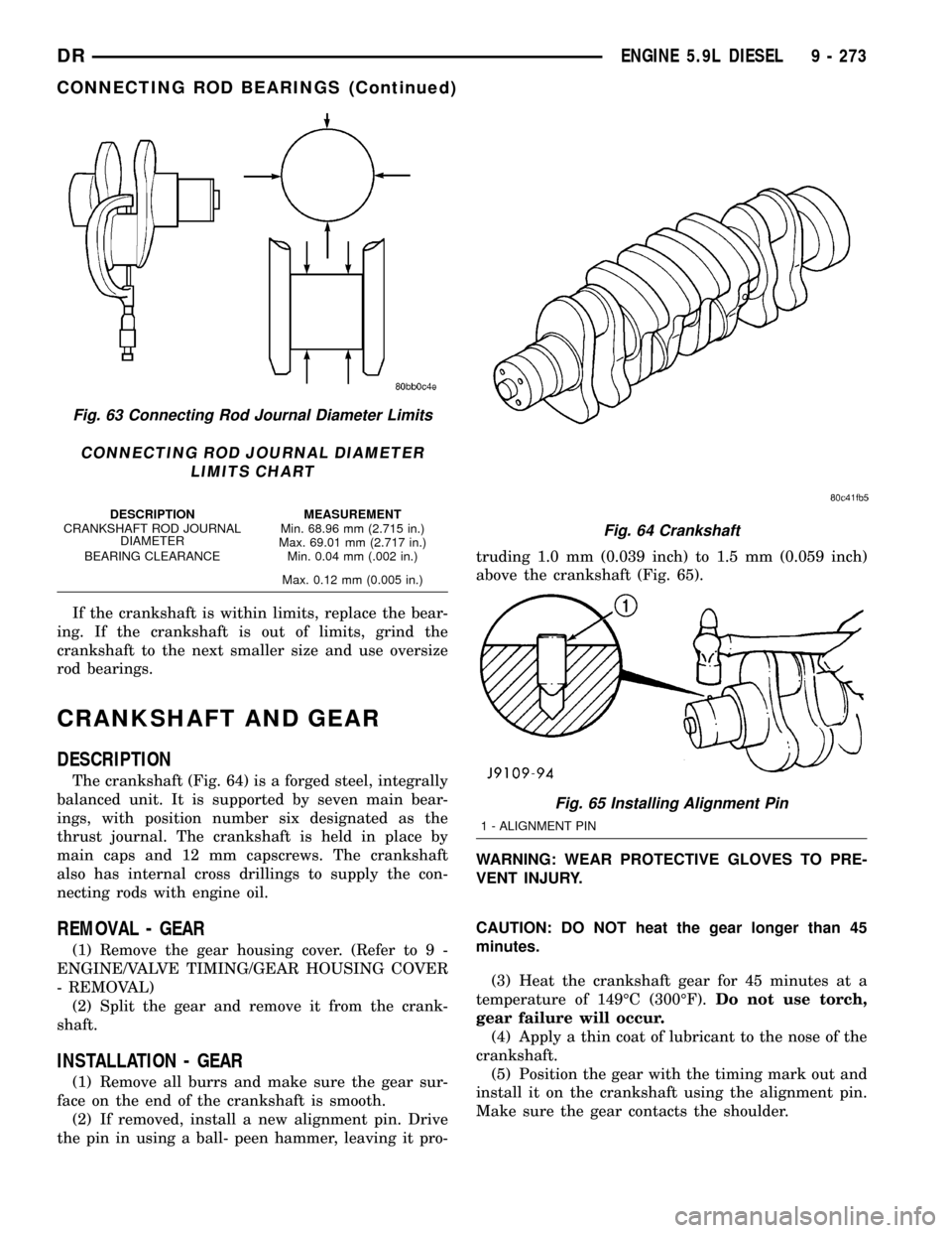
If the crankshaft is within limits, replace the bear-
ing. If the crankshaft is out of limits, grind the
crankshaft to the next smaller size and use oversize
rod bearings.
CRANKSHAFT AND GEAR
DESCRIPTION
The crankshaft (Fig. 64) is a forged steel, integrally
balanced unit. It is supported by seven main bear-
ings, with position number six designated as the
thrust journal. The crankshaft is held in place by
main caps and 12 mm capscrews. The crankshaft
also has internal cross drillings to supply the con-
necting rods with engine oil.
REMOVAL - GEAR
(1) Remove the gear housing cover. (Refer to 9 -
ENGINE/VALVE TIMING/GEAR HOUSING COVER
- REMOVAL)
(2) Split the gear and remove it from the crank-
shaft.
INSTALLATION - GEAR
(1) Remove all burrs and make sure the gear sur-
face on the end of the crankshaft is smooth.
(2) If removed, install a new alignment pin. Drive
the pin in using a ball- peen hammer, leaving it pro-truding 1.0 mm (0.039 inch) to 1.5 mm (0.059 inch)
above the crankshaft (Fig. 65).
WARNING: WEAR PROTECTIVE GLOVES TO PRE-
VENT INJURY.
CAUTION: DO NOT heat the gear longer than 45
minutes.
(3) Heat the crankshaft gear for 45 minutes at a
temperature of 149ÉC (300ÉF).Do not use torch,
gear failure will occur.
(4) Apply a thin coat of lubricant to the nose of the
crankshaft.
(5) Position the gear with the timing mark out and
install it on the crankshaft using the alignment pin.
Make sure the gear contacts the shoulder.
Fig. 63 Connecting Rod Journal Diameter Limits
CONNECTING ROD JOURNAL DIAMETER
LIMITS CHART
DESCRIPTION MEASUREMENT
CRANKSHAFT ROD JOURNAL
DIAMETERMin. 68.96 mm (2.715 in.)
Max. 69.01 mm (2.717 in.)
BEARING CLEARANCE Min. 0.04 mm (.002 in.)
Max. 0.12 mm (0.005 in.)
Fig. 64 Crankshaft
Fig. 65 Installing Alignment Pin
1 - ALIGNMENT PIN
DRENGINE 5.9L DIESEL 9 - 273
CONNECTING ROD BEARINGS (Continued)
Page 1497 of 2627
CRANKSHAFT MAIN
BEARINGS
STANDARD PROCEDURE - MAIN BEARING
CLEARANCE
Inspect the main bearing bores for damage or
abnormal wear.
(1) Remove bearings and measure main bearing
bore diameter after torquing main bearing cap bolts
to 176 Nm (130 ft. lbs.).
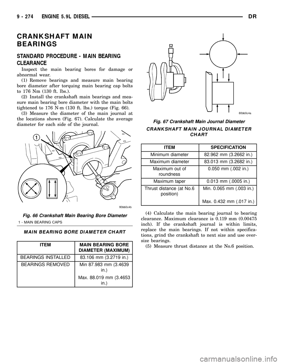
(2) Install the crankshaft main bearings and mea-
sure main bearing bore diameter with the main bolts
tightened to 176 N´m (130 ft. lbs.) torque (Fig. 66).
(3) Measure the diameter of the main journal at
the locations shown (Fig. 67). Calculate the average
diameter for each side of the journal.
MAIN BEARING BORE DIAMETER CHART
ITEM MAIN BEARING BORE
DIAMETER (MAXIMUM)
BEARINGS INSTALLED 83.106 mm (3.2719 in.)
BEARINGS REMOVED Min 87.983 mm (3.4639
in.)
Max. 88.019 mm (3.4653
in.)
CRANKSHAFT MAIN JOURNAL DIAMETER
CHART
ITEM SPECIFICATION
Minimum diameter 82.962 mm (3.2662 in.)
Maximum diameter 83.013 mm (3.2682 in.)
Maximum out of
roundness0.050 mm (.002 in.)
Maximum taper 0.013 mm (.0005 in.)
Thrust distance (at No.6
position)Min. 0.065 mm (.003 in.)
Max. 0.432 mm (.017 in.)
(4) Calculate the main bearing journal to bearing
clearance. Maximum clearance is 0.119 mm (0.00475
inch). If the crankshaft journal is within limits,
replace the main bearings. If not within specifica-
tions, grind the crankshaft to next size and use over-
size bearings.
(5) Measure thrust distance at the No.6 position.
Fig. 66 Crankshaft Main Bearing Bore Diameter
1 - MAIN BEARING CAPS
Fig. 67 Crankshaft Main Journal Diameter
9 - 274 ENGINE 5.9L DIESELDR
Page 1498 of 2627
CRANKSHAFT OIL SEAL - FRONT
REMOVAL
(1) Disconnect both battery negative cables.
(2) Raise vehicle on hoist.
(3) Partially drain engine coolant into container
suitable for re-use (Refer to 7 - COOLING - STAN-
DARD PROCEDURE).
(4) Lower vehicle.
(5) Remove radiator upper hose.
(6) Disconnect coolant recovery bottle from radia-
tor filler neck and lift bottle off of fan shroud.
(7) Disconnect windshield washer pump supply
hose and electrical connections and lift washer bottle
off of fan shroud.
(8)
Remove the fan shroud-to-radiator mounting bolts.
(9)Remove viscous fan/drive assembly. (Refer to 7 -
COOLING/ENGINE/RADIATOR FAN - REMOVAL).
(10) Remove cooling fan shroud and fan assembly
from the vehicle.
(11) Remove the accessory drive belt (Refer to 7 -
COOLING/ACCESSORY DRIVE/DRIVE BELTS -
REMOVAL).
(12) Remove the cooling fan support/hub from the
front of the engine.
(13) Raise the vehicle on hoist.
(14) Remove the crankshaft damper and speed
indicator ring.
(15) Remove power steering pump.
(16) Remove accessory drive belt tensioner.
(17) Remove the gear cover-to-housing bolts and
gently pry the cover away from the housing, taking
care not to mar the gasket surfaces. Remove crank
seal dust shield with cover.
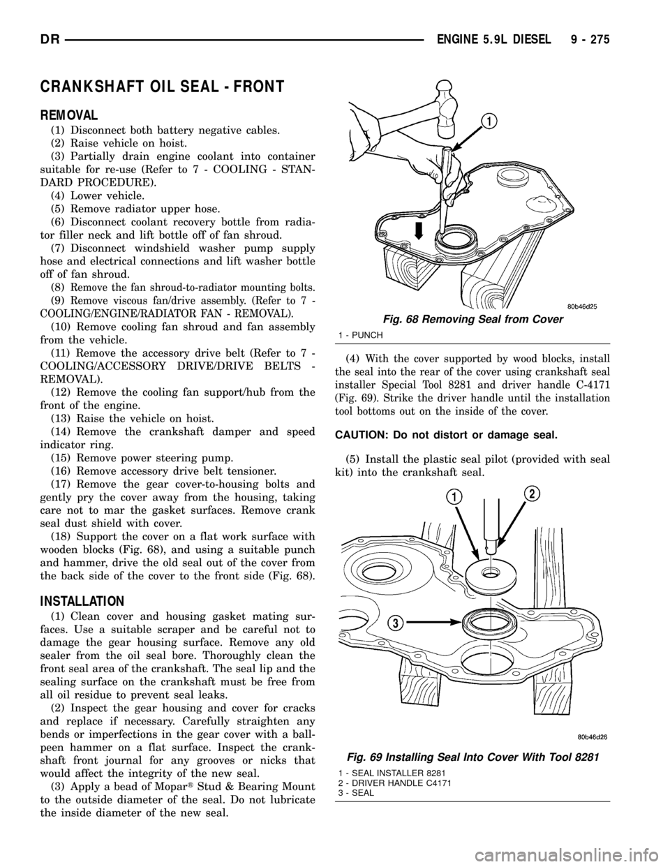
(18) Support the cover on a flat work surface with
wooden blocks (Fig. 68), and using a suitable punch
and hammer, drive the old seal out of the cover from
the back side of the cover to the front side (Fig. 68).
INSTALLATION
(1) Clean cover and housing gasket mating sur-
faces. Use a suitable scraper and be careful not to
damage the gear housing surface. Remove any old
sealer from the oil seal bore. Thoroughly clean the
front seal area of the crankshaft. The seal lip and the
sealing surface on the crankshaft must be free from
all oil residue to prevent seal leaks.
(2) Inspect the gear housing and cover for cracks
and replace if necessary. Carefully straighten any
bends or imperfections in the gear cover with a ball-
peen hammer on a flat surface. Inspect the crank-
shaft front journal for any grooves or nicks that
would affect the integrity of the new seal.
(3) Apply a bead of MopartStud & Bearing Mount
to the outside diameter of the seal. Do not lubricate
the inside diameter of the new seal.(4)
With the cover supported by wood blocks, install
the seal into the rear of the cover using crankshaft seal
installer Special Tool 8281 and driver handle C-4171
(Fig. 69). Strike the driver handle until the installation
tool bottoms out on the inside of the cover.
CAUTION: Do not distort or damage seal.
(5) Install the plastic seal pilot (provided with seal
kit) into the crankshaft seal.
Fig. 68 Removing Seal from Cover
1 - PUNCH
Fig. 69 Installing Seal Into Cover With Tool 8281
1 - SEAL INSTALLER 8281
2 - DRIVER HANDLE C4171
3 - SEAL
DRENGINE 5.9L DIESEL 9 - 275