1998 DODGE RAM 1500 loose steering
[x] Cancel search: loose steeringPage 1667 of 2627

KEY CYLINDER
REMOVAL
The ignition key must be in the key cylinder for
cylinder removal.
(1) Disconnect negative cable from battery.
(2) Remove upper and lower covers (shrouds) from
steering column.
(3) Place shifter in PARK position.
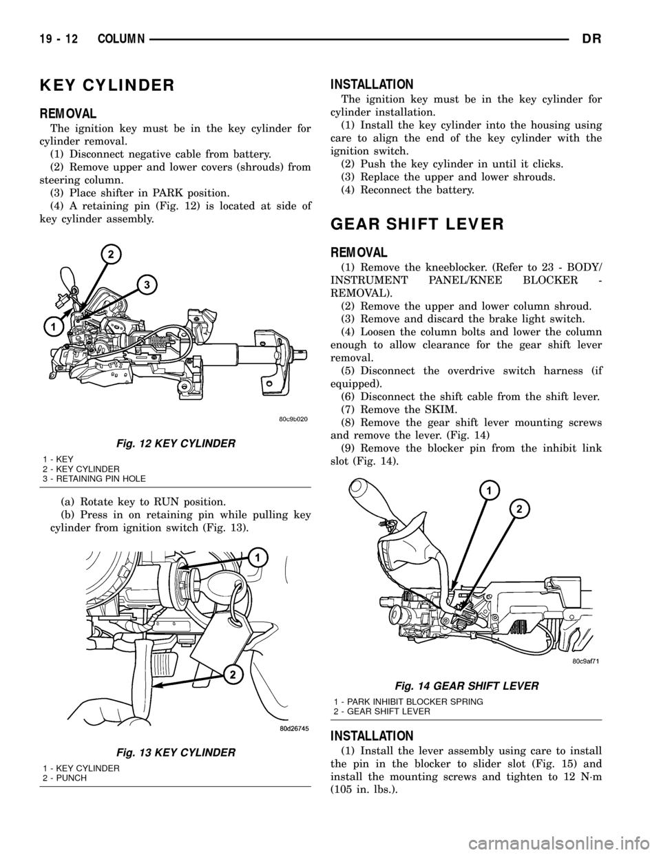
(4) A retaining pin (Fig. 12) is located at side of
key cylinder assembly.
(a) Rotate key to RUN position.
(b) Press in on retaining pin while pulling key
cylinder from ignition switch (Fig. 13).
INSTALLATION
The ignition key must be in the key cylinder for
cylinder installation.
(1) Install the key cylinder into the housing using
care to align the end of the key cylinder with the
ignition switch.
(2) Push the key cylinder in until it clicks.
(3) Replace the upper and lower shrouds.
(4) Reconnect the battery.
GEAR SHIFT LEVER
REMOVAL
(1) Remove the kneeblocker. (Refer to 23 - BODY/
INSTRUMENT PANEL/KNEE BLOCKER -
REMOVAL).
(2) Remove the upper and lower column shroud.
(3) Remove and discard the brake light switch.
(4) Loosen the column bolts and lower the column
enough to allow clearance for the gear shift lever
removal.
(5) Disconnect the overdrive switch harness (if
equipped).
(6) Disconnect the shift cable from the shift lever.
(7) Remove the SKIM.
(8) Remove the gear shift lever mounting screws
and remove the lever. (Fig. 14)
(9) Remove the blocker pin from the inhibit link
slot (Fig. 14).
INSTALLATION
(1) Install the lever assembly using care to install
the pin in the blocker to slider slot (Fig. 15) and
install the mounting screws and tighten to 12 N´m
(105 in. lbs.).
Fig. 12 KEY CYLINDER
1 - KEY
2 - KEY CYLINDER
3 - RETAINING PIN HOLE
Fig. 13 KEY CYLINDER
1 - KEY CYLINDER
2 - PUNCH
Fig. 14 GEAR SHIFT LEVER
1 - PARK INHIBIT BLOCKER SPRING
2 - GEAR SHIFT LEVER
19 - 12 COLUMNDR
Page 1687 of 2627

LINKAGE - INDEPENDENT FRONT SUSPENSION
TABLE OF CONTENTS
page page
LINKAGE - INDEPENDENT FRONT
SUSPENSION
DIAGNOSIS AND TESTING - OUTER TIE ROD
END ................................32TIE ROD END
REMOVAL - OUTER TIE ROD END..........32
INSTALLATION - OUTER TIE ROD END......33
LINKAGE - INDEPENDENT
FRONT SUSPENSION
DIAGNOSIS AND TESTING - OUTER TIE ROD
END
NOTE: If the outer tie rod end is equipped with a
lubrication fitting, grease the joint then road test
the vehicle before performing test.
(1) Raise the front of the vehicle. Place safety floor
stands under both lower control arms as far outboard
as possible. Lower the vehicle to allow the stands to
support some or all of the vehicle weight.
(2) Remove the front tires.
(3) Mount a dial indicator solidly to the vehicle
steering knuckle and then zero the dial indicator.
(4) Position indicator plunger on the topside of the
outer tie rod end.
NOTE: The dial indicator plunger must be perpen-
dicular to the machined surface of the outer tie rod
end.
(5) Position a pry bar in order to pry downwards
on the outer tie rod end.
(6) If the travel exceeds 0.5 mm (0.020 in.), replace
the outer tie rod end (Refer to 19 - STEERING/
LINKAGE/TIE ROD END - REMOVAL).
(7) If the outer tie rod end is within specs reinstall
the front tires (Refer to 22 - TIRES/WHEELS/
WHEELS - STANDARD PROCEDURE).
TIE ROD END
REMOVAL - OUTER TIE ROD END
NOTE: Do not twist the boot anytime during
removal or installation.
(1) Loosen the jam nut.
(2) Remove the outer tie rod end nut from the ball
stud.
(3) Separate the tie rod ball stud from the knuckle
with Remover 8677 (Fig. 1).
(4) Unthread the outer tie rod end from the inner
tie rod.
Fig. 1 TIE ROD SEPARATION
1 - TIE ROD END
2 - SPECIAL TOOL 8677
19 - 32 LINKAGE - INDEPENDENT FRONT SUSPENSIONDR
Page 1696 of 2627

(8) Fill the system with fluid and perform Steering
Pump Initial Operation, (Refer to 19 - STEERING/
PUMP - STANDARD PROCEDURE).
(9) Start the engine and run it for fifteen minutes
then stop the engine.
(10) Remove the return line/lines from the pump
and plug the pump port/ports.
(11) Pour fresh fluid into the reservoir and check
the draining fluid for contamination. If the fluid is
still contaminated, then flush the system again.
(12) Install the return line/lines and perform
Steering Pump Initial Operation, (Refer to 19 -
STEERING/PUMP - STANDARD PROCEDURE).
REMOVAL
REMOVAL - GAS
(1) Drain and siphon the power steering fluid from
the reservoir.
(2) Remove the serpentine belt.
CAUTION: Do not remove the fitting on the pump
that the high pressure hose screws into. The fitting
may come loose unless it is backed up using
another wrench. If the fitting does come loose, it
must be retightened before continuing. (57 - 67Nm,
40 - 50 lbft) If this fitting comes out of the pump
body, the internal spring and valve parts will fall out
of the pump and they cannot be reinstalled prop-
erly. If this occurs the pump needs to be replaced
with a new pump.
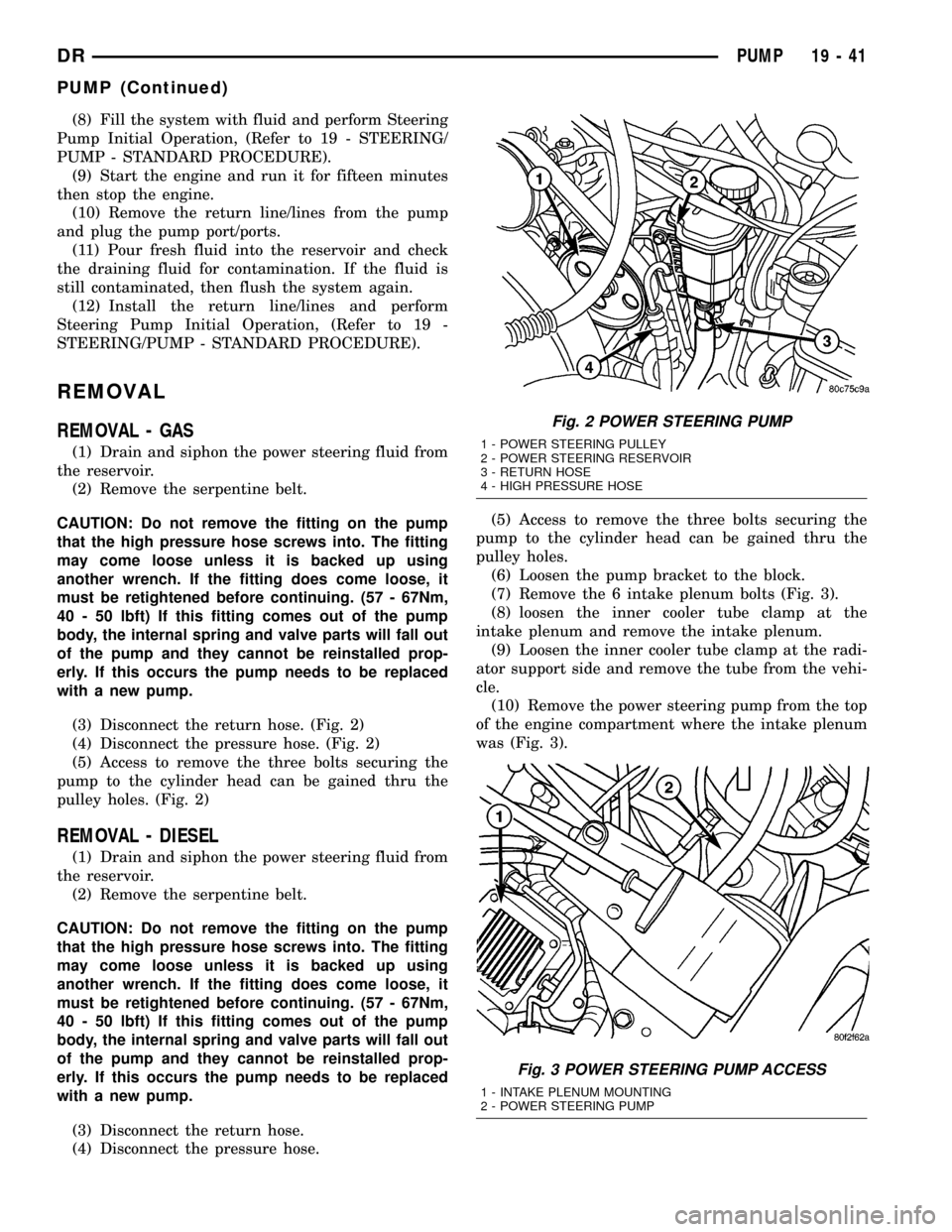
(3) Disconnect the return hose. (Fig. 2)
(4) Disconnect the pressure hose. (Fig. 2)
(5) Access to remove the three bolts securing the
pump to the cylinder head can be gained thru the
pulley holes. (Fig. 2)
REMOVAL - DIESEL
(1) Drain and siphon the power steering fluid from
the reservoir.
(2) Remove the serpentine belt.
CAUTION: Do not remove the fitting on the pump
that the high pressure hose screws into. The fitting
may come loose unless it is backed up using
another wrench. If the fitting does come loose, it
must be retightened before continuing. (57 - 67Nm,
40 - 50 lbft) If this fitting comes out of the pump
body, the internal spring and valve parts will fall out
of the pump and they cannot be reinstalled prop-
erly. If this occurs the pump needs to be replaced
with a new pump.
(3) Disconnect the return hose.
(4) Disconnect the pressure hose.(5) Access to remove the three bolts securing the
pump to the cylinder head can be gained thru the
pulley holes.
(6) Loosen the pump bracket to the block.
(7) Remove the 6 intake plenum bolts (Fig. 3).
(8) loosen the inner cooler tube clamp at the
intake plenum and remove the intake plenum.
(9) Loosen the inner cooler tube clamp at the radi-
ator support side and remove the tube from the vehi-
cle.
(10) Remove the power steering pump from the top
of the engine compartment where the intake plenum
was (Fig. 3).
Fig. 2 POWER STEERING PUMP
1 - POWER STEERING PULLEY
2 - POWER STEERING RESERVOIR
3 - RETURN HOSE
4 - HIGH PRESSURE HOSE
Fig. 3 POWER STEERING PUMP ACCESS
1 - INTAKE PLENUM MOUNTING
2 - POWER STEERING PUMP
DRPUMP 19 - 41
PUMP (Continued)
Page 1702 of 2627

PULLEY
REMOVAL
CAUTION: Do not reuse the old power steering
pump pulley it is not intended for reuse. A new pul-
ley must be installed if removed.
(1) Remove the power steering pump assembly,
(Refer to 19 - STEERING/PUMP - REMOVAL).
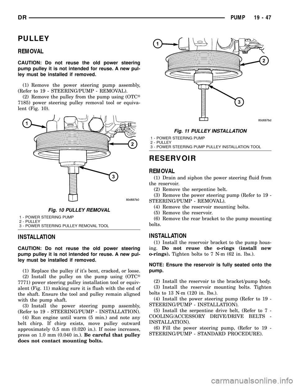
(2) Remove the pulley from the pump using (OTCt
7185) power steering pulley removal tool or equiva-
lent (Fig. 10).
INSTALLATION
CAUTION: Do not reuse the old power steering
pump pulley it is not intended for reuse. A new pul-
ley must be installed if removed.
(1) Replace the pulley if it's bent, cracked, or loose.
(2) Install the pulley on the pump using (OTCt
7771) power steering pulley installation tool or equiv-
alent (Fig. 11) making sure it is flush with the end of
the shaft. Ensure the tool and pulley remain aligned
with the pump shaft.
(3) Install the power steering pump assembly,
(Refer to 19 - STEERING/PUMP - INSTALLATION).
(4) Run engine until warm (5 min.) and note any
belt chirp. If chirp exists, move pulley outward
approximately 0.5 mm (0.020 in.). If noise increases,
press on 1.0 mm (0.040 in.).Be careful that pulley
does not contact mounting bolts.
RESERVOIR
REMOVAL
(1) Drain and siphon the power steering fluid from
the reservoir.
(2) Remove the serpentine belt.
(3) Remove the power steering pump (Refer to 19 -
STEERING/PUMP - REMOVAL).
(4) Remove the reservoir mounting bolts.
(5) Remove the reservoir.
(6) Remove the rear bracket to the pump mounting
bolts.
INSTALLATION
(1) Install the reservoir bracket to the pump hous-
ing.Do not reuse the o-rings (install new
o-rings).Tighten bolts to 7 N´m (62 in. lbs.).
NOTE: Ensure the reservoir is fully seated onto the
pump.
(2) Install the reservoir to the bracket/pump body.
(3) Install the reservoir mounting bolts. Tighten
bolts to 13 N´m (120 in. lbs.).
(4) Install the power steering pump (Refer to 19 -
STEERING/PUMP - INSTALLATION).
(5) Install the serpentine drive belt, (Refer to 7 -
COOLING/ACCESSORY DRIVE/DRIVE BELTS -
INSTALLATION).
(6) Fill the power steering pump, (Refer to 19 -
STEERING/PUMP - STANDARD PROCEDURE).
Fig. 10 PULLEY REMOVAL
1 - POWER STEERING PUMP
2 - PULLEY
3 - POWER STEERING PULLEY REMOVAL TOOL
Fig. 11 PULLEY INSTALLATION
1 - POWER STEERING PUMP
2 - PULLEY
3 - POWER STEERING PUMP PULLEY INSTALLATION TOOL
DRPUMP 19 - 47
Page 2348 of 2627

(1) Remove the left a-pillar trim. (Refer to 23 -
BODY/INTERIOR/A-PILLAR TRIM/GRAB HANDLE
- REMOVAL)
(2) Remove the top cover. (Refer to 23 - BODY/IN-
STRUMENT PANEL/INSTRUMENT PANEL TOP
COVER - REMOVAL)
(3) Disconnect the headliner harness electrical con-
nector at the a-pillar.
(4) Using a trim stick C-4755 or equivalent, from
the notch on the bottom, remove the left side cover.
(Fig. 20)
(5) Remove the steering column. (Refer to 19 -
STEERING/COLUMN - REMOVAL)
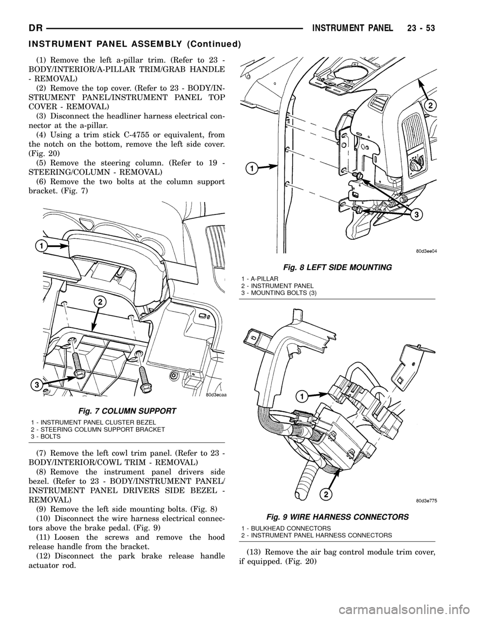
(6) Remove the two bolts at the column support
bracket. (Fig. 7)
(7) Remove the left cowl trim panel. (Refer to 23 -
BODY/INTERIOR/COWL TRIM - REMOVAL)
(8) Remove the instrument panel drivers side
bezel. (Refer to 23 - BODY/INSTRUMENT PANEL/
INSTRUMENT PANEL DRIVERS SIDE BEZEL -
REMOVAL)
(9) Remove the left side mounting bolts. (Fig. 8)
(10) Disconnect the wire harness electrical connec-
tors above the brake pedal. (Fig. 9)
(11) Loosen the screws and remove the hood
release handle from the bracket.
(12) Disconnect the park brake release handle
actuator rod.(13) Remove the air bag control module trim cover,
if equipped. (Fig. 20)
Fig. 7 COLUMN SUPPORT
1 - INSTRUMENT PANEL CLUSTER BEZEL
2 - STEERING COLUMN SUPPORT BRACKET
3 - BOLTS
Fig. 8 LEFT SIDE MOUNTING
1 - A-PILLAR
2 - INSTRUMENT PANEL
3 - MOUNTING BOLTS (3)
Fig. 9 WIRE HARNESS CONNECTORS
1 - BULKHEAD CONNECTORS
2 - INSTRUMENT PANEL HARNESS CONNECTORS
DRINSTRUMENT PANEL 23 - 53
INSTRUMENT PANEL ASSEMBLY (Continued)
Page 2355 of 2627

(3) Install the storage bin, if equipped. (Refer to 23
- BODY/INSTRUMENT PANEL/STORAGE BIN -
INSTALLATION)
(4) Install the cup holder, if equipped. (Refer to 23
- BODY/INSTRUMENT PANEL/CUP HOLDER -
INSTALLATION)
(5) Install the glove box. (Refer to 23 - BODY/IN-
STRUMENT PANEL/GLOVE BOX - INSTALLA-
TION)
(6) Install the ash receiver. (Refer to 23 - BODY/
INSTRUMENT PANEL/ASH RECEIVER - INSTAL-
LATION)
(7) Install the passenger side cowl trim panel.
(Refer to 23 - BODY/INTERIOR/COWL TRIM -
INSTALLATION)
(8) Position the passenger side end cap and seat
fully.
STEERING COLUMN OPENING
COVER
REMOVAL
WARNING: ON VEHICLES EQUIPPED WITH AIR-
BAGS, DISABLE THE AIRBAG SYSTEM BEFORE
ATTEMPTING ANY STEERING WHEEL, STEERING
COLUMN, SEAT BELT TENSIONER, OR INSTRU-
MENT PANEL COMPONENT DIAGNOSIS OR SER-
VICE. DISCONNECT AND ISOLATE THE BATTERY
NEGATIVE (GROUND) CABLE, THEN WAIT TWO
MINUTES FOR THE AIRBAG SYSTEM CAPACITOR
TO DISCHARGE BEFORE PERFORMING FURTHER
DIAGNOSIS OR SERVICE. THIS IS THE ONLY SURE
WAY TO DISABLE THE AIRBAG SYSTEM. FAILURE
TO TAKE THE PROPER PRECAUTIONS COULD
RESULT IN ACCIDENTAL AIRBAG DEPLOYMENT
AND POSSIBLE PERSONAL INJURY.
(1) Remove the two lower screws. (Fig. 21)
(2) Using a trim stick C-4755 or equivalent,
release the upper clips and remove the cover.
INSTALLATION
WARNING: ON VEHICLES EQUIPPED WITH AIR-
BAGS, DISABLE THE AIRBAG SYSTEM BEFORE
ATTEMPTING ANY STEERING WHEEL, STEERING
COLUMN, SEAT BELT TENSIONER, OR INSTRU-
MENT PANEL COMPONENT DIAGNOSIS OR SER-
VICE. DISCONNECT AND ISOLATE THE BATTERY
NEGATIVE (GROUND) CABLE, THEN WAIT TWO
MINUTES FOR THE AIRBAG SYSTEM CAPACITOR
TO DISCHARGE BEFORE PERFORMING FURTHER
DIAGNOSIS OR SERVICE. THIS IS THE ONLY SURE
WAY TO DISABLE THE AIRBAG SYSTEM. FAILURETO TAKE THE PROPER PRECAUTIONS COULD
RESULT IN ACCIDENTAL AIRBAG DEPLOYMENT
AND POSSIBLE PERSONAL INJURY.
(1) Position the cover and seat the upper clips
fully.
(2) Install the two lower screws.
STEERING COLUMN OPENING
SUPPORT BRACKET
REMOVAL
(1) Remove the steering column opening cover.
(Refer to 23 - BODY/INSTRUMENT PANEL/STEER-
ING COLUMN OPENING COVER - REMOVAL)
(2) Remove the two screws and remove the diag-
nostic connector.
(3) Loosen the screws and remove the hood release
handle from the bracket.
(4) Remove the two bracket screws and slide
upward off the locating tabs to remove. (Fig. 22)
INSTALLATION
(1) Position the bracket onto the locating tabs and
slide down.
(2) Install the two screws.
(3) Install the diagnostic connector and install the
two screws.
(4) Install the hood release handle and tighten the
screws.
Fig. 21 STEERING COLUMN OPENING COVER
1 - SCREWS (2)
2 - COVER
23 - 60 INSTRUMENT PANELDR
INSTRUMENT PANEL LOWER SURROUND (Continued)