1998 DODGE RAM 1500 Front wiring
[x] Cancel search: Front wiringPage 1154 of 2627
8W-91 CONNECTOR/GROUND/SPLICE LOCATION
TABLE OF CONTENTS
page
CONNECTOR/GROUND/SPLICE LOCATION
DESCRIPTION..........................1
CONNECTOR/GROUND/SPLICE
LOCATION
DESCRIPTION
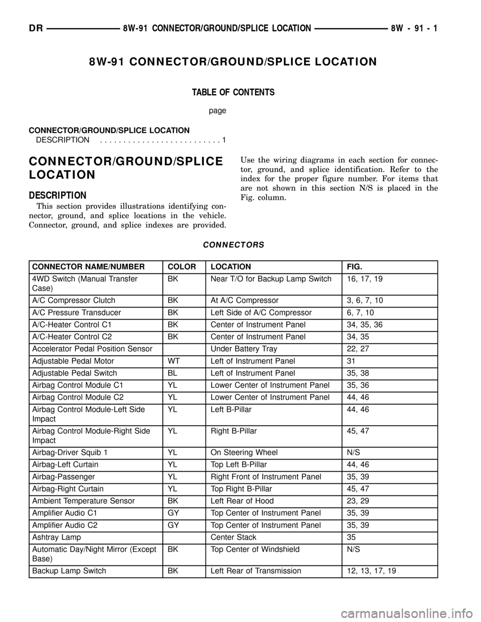
This section provides illustrations identifying con-
nector, ground, and splice locations in the vehicle.
Connector, ground, and splice indexes are provided.Use the wiring diagrams in each section for connec-
tor, ground, and splice identification. Refer to the
index for the proper figure number. For items that
are not shown in this section N/S is placed in the
Fig. column.
CONNECTORS
CONNECTOR NAME/NUMBER COLOR LOCATION FIG.
4WD Switch (Manual Transfer
Case)BK Near T/O for Backup Lamp Switch 16, 17, 19
A/C Compressor Clutch BK At A/C Compressor 3, 6, 7, 10
A/C Pressure Transducer BK Left Side of A/C Compressor 6, 7, 10
A/C-Heater Control C1 BK Center of Instrument Panel 34, 35, 36
A/C-Heater Control C2 BK Center of Instrument Panel 34, 35
Accelerator Pedal Position Sensor Under Battery Tray 22, 27
Adjustable Pedal Motor WT Left of Instrument Panel 31
Adjustable Pedal Switch BL Left of Instrument Panel 35, 38
Airbag Control Module C1 YL Lower Center of Instrument Panel 35, 36
Airbag Control Module C2 YL Lower Center of Instrument Panel 44, 46
Airbag Control Module-Left Side
ImpactYL Left B-Pillar 44, 46
Airbag Control Module-Right Side
ImpactYL Right B-Pillar 45, 47
Airbag-Driver Squib 1 YL On Steering Wheel N/S
Airbag-Left Curtain YL Top Left B-Pillar 44, 46
Airbag-Passenger YL Right Front of Instrument Panel 35, 39
Airbag-Right Curtain YL Top Right B-Pillar 45, 47
Ambient Temperature Sensor BK Left Rear of Hood 23, 29
Amplifier Audio C1 GY Top Center of Instrument Panel 35, 39
Amplifier Audio C2 GY Top Center of Instrument Panel 35, 39
Ashtray Lamp Center Stack 35
Automatic Day/Night Mirror (Except
Base)BK Top Center of Windshield N/S
Backup Lamp Switch BK Left Rear of Transmission 12, 13, 17, 19
DR8W-91 CONNECTOR/GROUND/SPLICE LOCATION 8W - 91 - 1
Page 1216 of 2627
8W-97 POWER DISTRIBUTION
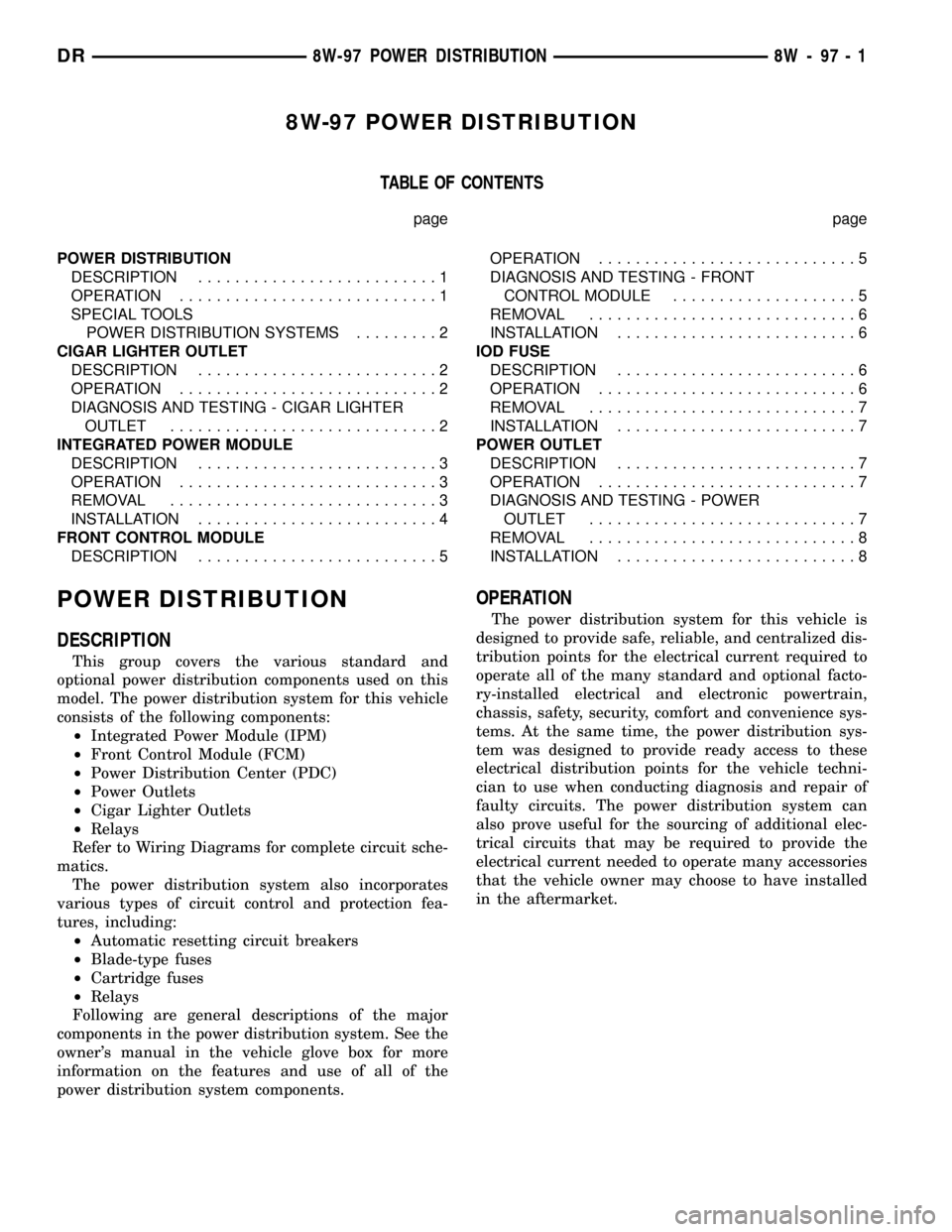
TABLE OF CONTENTS
page page
POWER DISTRIBUTION
DESCRIPTION..........................1
OPERATION............................1
SPECIAL TOOLS
POWER DISTRIBUTION SYSTEMS.........2
CIGAR LIGHTER OUTLET
DESCRIPTION..........................2
OPERATION............................2
DIAGNOSIS AND TESTING - CIGAR LIGHTER
OUTLET.............................2
INTEGRATED POWER MODULE
DESCRIPTION..........................3
OPERATION............................3
REMOVAL.............................3
INSTALLATION..........................4
FRONT CONTROL MODULE
DESCRIPTION..........................5OPERATION............................5
DIAGNOSIS AND TESTING - FRONT
CONTROL MODULE....................5
REMOVAL.............................6
INSTALLATION..........................6
IOD FUSE
DESCRIPTION..........................6
OPERATION............................6
REMOVAL.............................7
INSTALLATION..........................7
POWER OUTLET
DESCRIPTION..........................7
OPERATION............................7
DIAGNOSIS AND TESTING - POWER
OUTLET.............................7
REMOVAL.............................8
INSTALLATION..........................8
POWER DISTRIBUTION
DESCRIPTION
This group covers the various standard and
optional power distribution components used on this
model. The power distribution system for this vehicle
consists of the following components:
²Integrated Power Module (IPM)
²Front Control Module (FCM)
²Power Distribution Center (PDC)
²Power Outlets
²Cigar Lighter Outlets
²Relays
Refer to Wiring Diagrams for complete circuit sche-
matics.
The power distribution system also incorporates
various types of circuit control and protection fea-
tures, including:
²Automatic resetting circuit breakers
²Blade-type fuses
²Cartridge fuses
²Relays
Following are general descriptions of the major
components in the power distribution system. See the
owner's manual in the vehicle glove box for more
information on the features and use of all of the
power distribution system components.
OPERATION
The power distribution system for this vehicle is
designed to provide safe, reliable, and centralized dis-
tribution points for the electrical current required to
operate all of the many standard and optional facto-
ry-installed electrical and electronic powertrain,
chassis, safety, security, comfort and convenience sys-
tems. At the same time, the power distribution sys-
tem was designed to provide ready access to these
electrical distribution points for the vehicle techni-
cian to use when conducting diagnosis and repair of
faulty circuits. The power distribution system can
also prove useful for the sourcing of additional elec-
trical circuits that may be required to provide the
electrical current needed to operate many accessories
that the vehicle owner may choose to have installed
in the aftermarket.
DR8W-97 POWER DISTRIBUTION 8W - 97 - 1
Page 1218 of 2627
INTEGRATED POWER MODULE
DESCRIPTION
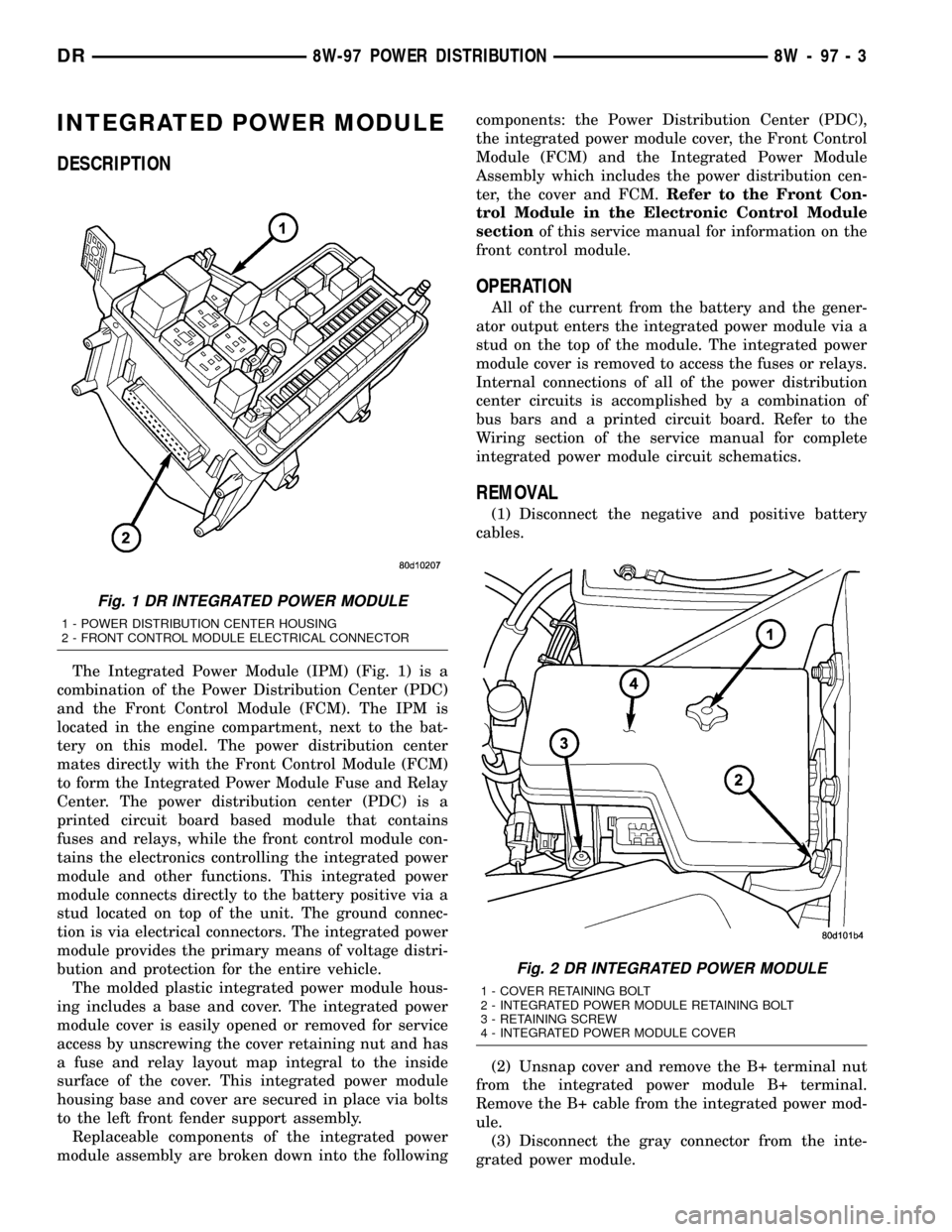
The Integrated Power Module (IPM) (Fig. 1) is a
combination of the Power Distribution Center (PDC)
and the Front Control Module (FCM). The IPM is
located in the engine compartment, next to the bat-
tery on this model. The power distribution center
mates directly with the Front Control Module (FCM)
to form the Integrated Power Module Fuse and Relay
Center. The power distribution center (PDC) is a
printed circuit board based module that contains
fuses and relays, while the front control module con-
tains the electronics controlling the integrated power
module and other functions. This integrated power
module connects directly to the battery positive via a
stud located on top of the unit. The ground connec-
tion is via electrical connectors. The integrated power
module provides the primary means of voltage distri-
bution and protection for the entire vehicle.
The molded plastic integrated power module hous-
ing includes a base and cover. The integrated power
module cover is easily opened or removed for service
access by unscrewing the cover retaining nut and has
a fuse and relay layout map integral to the inside
surface of the cover. This integrated power module
housing base and cover are secured in place via bolts
to the left front fender support assembly.
Replaceable components of the integrated power
module assembly are broken down into the followingcomponents: the Power Distribution Center (PDC),
the integrated power module cover, the Front Control
Module (FCM) and the Integrated Power Module
Assembly which includes the power distribution cen-
ter, the cover and FCM.Refer to the Front Con-
trol Module in the Electronic Control Module
sectionof this service manual for information on the
front control module.
OPERATION
All of the current from the battery and the gener-
ator output enters the integrated power module via a
stud on the top of the module. The integrated power
module cover is removed to access the fuses or relays.
Internal connections of all of the power distribution
center circuits is accomplished by a combination of
bus bars and a printed circuit board. Refer to the
Wiring section of the service manual for complete
integrated power module circuit schematics.
REMOVAL
(1) Disconnect the negative and positive battery
cables.
(2) Unsnap cover and remove the B+ terminal nut
from the integrated power module B+ terminal.
Remove the B+ cable from the integrated power mod-
ule.
(3) Disconnect the gray connector from the inte-
grated power module.
Fig. 1 DR INTEGRATED POWER MODULE
1 - POWER DISTRIBUTION CENTER HOUSING
2 - FRONT CONTROL MODULE ELECTRICAL CONNECTOR
Fig. 2 DR INTEGRATED POWER MODULE
1 - COVER RETAINING BOLT
2 - INTEGRATED POWER MODULE RETAINING BOLT
3 - RETAINING SCREW
4 - INTEGRATED POWER MODULE COVER
DR8W-97 POWER DISTRIBUTION 8W - 97 - 3
Page 1234 of 2627
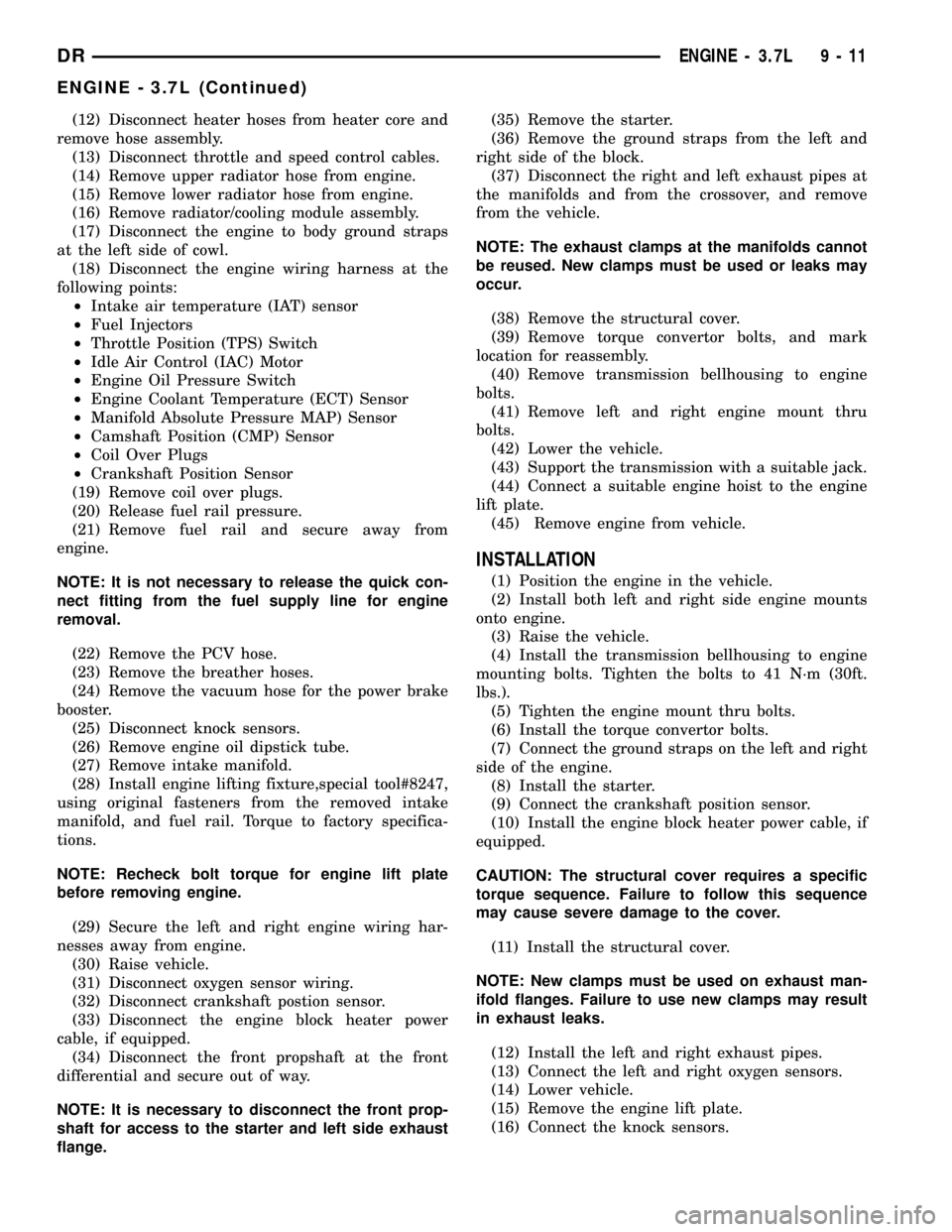
(12) Disconnect heater hoses from heater core and
remove hose assembly.
(13) Disconnect throttle and speed control cables.
(14) Remove upper radiator hose from engine.
(15) Remove lower radiator hose from engine.
(16) Remove radiator/cooling module assembly.
(17) Disconnect the engine to body ground straps
at the left side of cowl.
(18) Disconnect the engine wiring harness at the
following points:
²Intake air temperature (IAT) sensor
²Fuel Injectors
²Throttle Position (TPS) Switch
²Idle Air Control (IAC) Motor
²Engine Oil Pressure Switch
²Engine Coolant Temperature (ECT) Sensor
²Manifold Absolute Pressure MAP) Sensor
²Camshaft Position (CMP) Sensor
²Coil Over Plugs
²Crankshaft Position Sensor
(19) Remove coil over plugs.
(20) Release fuel rail pressure.
(21) Remove fuel rail and secure away from
engine.
NOTE: It is not necessary to release the quick con-
nect fitting from the fuel supply line for engine
removal.
(22) Remove the PCV hose.
(23) Remove the breather hoses.
(24) Remove the vacuum hose for the power brake
booster.
(25) Disconnect knock sensors.
(26) Remove engine oil dipstick tube.
(27) Remove intake manifold.
(28) Install engine lifting fixture,special tool#8247,
using original fasteners from the removed intake
manifold, and fuel rail. Torque to factory specifica-
tions.
NOTE: Recheck bolt torque for engine lift plate
before removing engine.
(29) Secure the left and right engine wiring har-
nesses away from engine.
(30) Raise vehicle.
(31) Disconnect oxygen sensor wiring.
(32) Disconnect crankshaft postion sensor.
(33) Disconnect the engine block heater power
cable, if equipped.
(34) Disconnect the front propshaft at the front
differential and secure out of way.
NOTE: It is necessary to disconnect the front prop-
shaft for access to the starter and left side exhaust
flange.(35) Remove the starter.
(36) Remove the ground straps from the left and
right side of the block.
(37) Disconnect the right and left exhaust pipes at
the manifolds and from the crossover, and remove
from the vehicle.
NOTE: The exhaust clamps at the manifolds cannot
be reused. New clamps must be used or leaks may
occur.
(38) Remove the structural cover.
(39) Remove torque convertor bolts, and mark
location for reassembly.
(40) Remove transmission bellhousing to engine
bolts.
(41) Remove left and right engine mount thru
bolts.
(42) Lower the vehicle.
(43) Support the transmission with a suitable jack.
(44) Connect a suitable engine hoist to the engine
lift plate.
(45) Remove engine from vehicle.
INSTALLATION
(1) Position the engine in the vehicle.
(2) Install both left and right side engine mounts
onto engine.
(3) Raise the vehicle.
(4) Install the transmission bellhousing to engine
mounting bolts. Tighten the bolts to 41 N´m (30ft.
lbs.).
(5) Tighten the engine mount thru bolts.
(6) Install the torque convertor bolts.
(7) Connect the ground straps on the left and right
side of the engine.
(8) Install the starter.
(9) Connect the crankshaft position sensor.
(10) Install the engine block heater power cable, if
equipped.
CAUTION: The structural cover requires a specific
torque sequence. Failure to follow this sequence
may cause severe damage to the cover.
(11) Install the structural cover.
NOTE: New clamps must be used on exhaust man-
ifold flanges. Failure to use new clamps may result
in exhaust leaks.
(12) Install the left and right exhaust pipes.
(13) Connect the left and right oxygen sensors.
(14) Lower vehicle.
(15) Remove the engine lift plate.
(16) Connect the knock sensors.
DRENGINE - 3.7L 9 - 11
ENGINE - 3.7L (Continued)
Page 1321 of 2627
Position both the left and right side engine mount
brackets and install the through bolts and nuts.
Tighten nuts to4X2 vehicles95 N´m (70 ft. lbs.).
4X4 vehicles102 N´m (75 ft. lbs.).
(2)4X4 vehiclesInstall locknuts onto the engine
mount brackets. Tighten locknuts to 41 N´m (30 ft.
lbs.).
(3) Remove jack from under the transmission.
(4) Remove Engine Lifting Fixture Special Tool
8347 (Fig. 4).
(5) Remove Special Tools 8400 Lifting Studs.
(6) Position generator wiring behind the oil dip-
stick tube, then install the oil dipstick tube upper
mounting bolt.
(7) Connect both left and right side body ground
straps.
(8) Install power steering pump.
(9) Connect fuel supply line quick connect fitting
(Refer to 14 - FUEL SYSTEM/FUEL DELIVERY/
QUICK CONNECT FITTING - STANDARD PROCE-
DURE).
(10) Connect the vacuum lines at the throttle body
and intake manifold.
(11) Connect engine harness at the following
points (Fig. 3):
²Intake Air Temperature (IAT) Sensor
²Idle Air Control (IAC) Motor
²Fuel Injectors
²Throttle Position (TPS) Switch
²Engine Oil Pressure Switch
²Engine Coolant Temperature (ECT) Sensor
²Manifold Absolute Pressure (MAP) Sensor
²Camshaft Position (CMP) Sensor
²Coil Over Plugs
(12) Position and install heater hoses and tubes
onto intake manifold.
(13) Install the heater hoses onto the heater core
and the engine front cover.
(14) Install generator (Refer to 8 - ELECTRICAL/
CHARGING/GENERATOR - INSTALLATION).
(15) Install A/C condenser (Refer to 24 - HEATING
& AIR CONDITIONING/PLUMBING/A/C CON-
DENSER - INSTALLATION), radiator (Refer to 7 -
COOLING/ENGINE/RADIATOR - INSTALLATION)
and transmission oil cooler.
(16) Connect radiator upper and lower hoses.
(17) Connect the transmission oil cooler lines to
the radiator.
(18) Install accessory drive belt (Refer to 7 -
COOLING/ACCESSORY DRIVE/DRIVE BELTS -INSTALLATION), fan assembly and shroud (Refer to
7 - COOLING/ENGINE/FAN DRIVE VISCOUS
CLUTCH - INSTALLATION).
(19) Install A/C compressor (Refer to 24 - HEAT-
ING & AIR CONDITIONING/PLUMBING/A/C COM-
PRESSOR - INSTALLATION).
(20) Install both breathers. Connect tube to both
crankcase breathers (Fig. 2).
(21) Connect throttle and speed control cables.
(22) Install throttle body resonator assembly and
air inlet hose. Tighten clamps 4 N´m (35 in. lbs.).
(23) Raise vehicle.
(24) Install transmission to engine mounting bolts.
Tighten the bolts to 41 N´m (30 ft. lbs.).
(25) Install torque converter bolts (Automatic
Transmission Only).
(26) Connect crankshaft position sensor (Fig. 1).
(27)4X4 vehiclesPosition and install the axle
isolator bracket onto the axle, transmission and
engine block. Tighten bolts to specification (Refer to 9
- ENGINE - SPECIFICATIONS).
(28) Install starter (Refer to 8 - ELECTRICAL/
STARTING/STARTER MOTOR - INSTALLATION).
CAUTION: The structural cover requires a specific
torque sequence. Failure to follow this sequence
may cause severe damage to the cover.
(29) Install structural cover (Refer to 9 - ENGINE/
ENGINE BLOCK/STRUCTURAL COVER - INSTAL-
LATION).
(30) Install exhaust crossover pipe.
(31) Install engine block heater power cable, If
equipped.
(32)4X4 vehiclesConnect axle vent tube to left
side engine mount.
(33) Lower vehicle.
(34) Check and fill engine oil.
(35) Recharge the A/C system (Refer to 24 - HEAT-
ING & AIR CONDITIONING/PLUMBING/REFRIG-
ERANT - STANDARD PROCEDURE).
(36) Refill the engine cooling system (Refer to 7 -
COOLING - STANDARD PROCEDURE).
(37) Install the battery tray and battery.
(38) Connect the battery positive and negative
cables.
(39) Start the engine and check for leaks.
9 - 98 ENGINE - 4.7LDR
ENGINE - 4.7L (Continued)
Page 1520 of 2627
(13) Install the cooling fan (Refer to 7 - COOLING/
ENGINE/RADIATOR FAN - INSTALLATION).
(14) Connect battery negative cables.
(15) Start engine and check for oil leaks.
INTAKE MANIFOLD
REMOVAL
(1) Disconnect the battery negative cables.
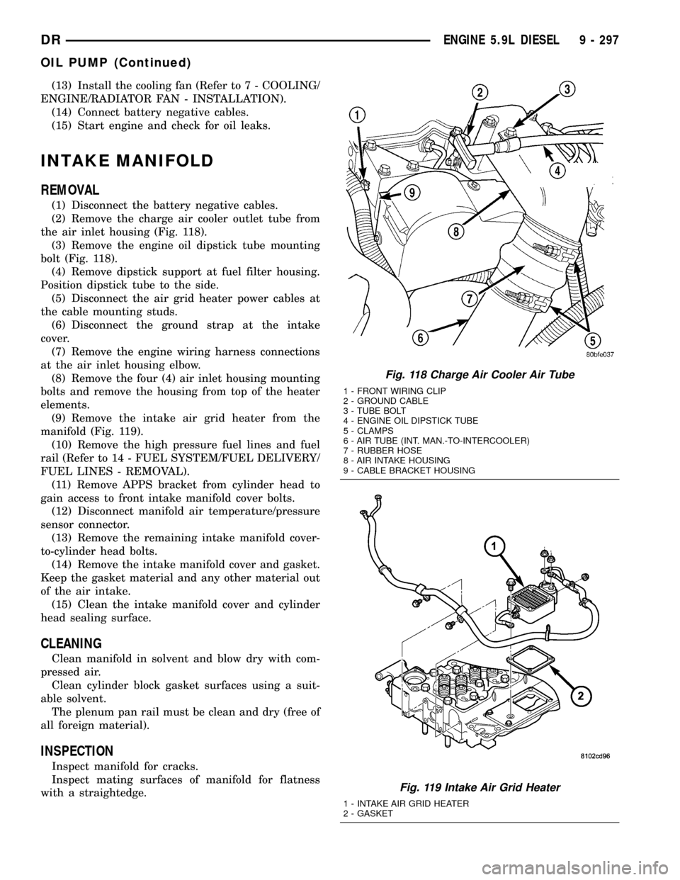
(2) Remove the charge air cooler outlet tube from
the air inlet housing (Fig. 118).
(3) Remove the engine oil dipstick tube mounting
bolt (Fig. 118).
(4) Remove dipstick support at fuel filter housing.
Position dipstick tube to the side.
(5) Disconnect the air grid heater power cables at
the cable mounting studs.
(6) Disconnect the ground strap at the intake
cover.
(7) Remove the engine wiring harness connections
at the air inlet housing elbow.
(8) Remove the four (4) air inlet housing mounting
bolts and remove the housing from top of the heater
elements.
(9) Remove the intake air grid heater from the
manifold (Fig. 119).
(10) Remove the high pressure fuel lines and fuel
rail (Refer to 14 - FUEL SYSTEM/FUEL DELIVERY/
FUEL LINES - REMOVAL).
(11) Remove APPS bracket from cylinder head to
gain access to front intake manifold cover bolts.
(12) Disconnect manifold air temperature/pressure
sensor connector.
(13) Remove the remaining intake manifold cover-
to-cylinder head bolts.
(14) Remove the intake manifold cover and gasket.
Keep the gasket material and any other material out
of the air intake.
(15) Clean the intake manifold cover and cylinder
head sealing surface.
CLEANING
Clean manifold in solvent and blow dry with com-
pressed air.
Clean cylinder block gasket surfaces using a suit-
able solvent.
The plenum pan rail must be clean and dry (free of
all foreign material).
INSPECTION
Inspect manifold for cracks.
Inspect mating surfaces of manifold for flatness
with a straightedge.
Fig. 118 Charge Air Cooler Air Tube
1 - FRONT WIRING CLIP
2 - GROUND CABLE
3 - TUBE BOLT
4 - ENGINE OIL DIPSTICK TUBE
5 - CLAMPS
6 - AIR TUBE (INT. MAN.-TO-INTERCOOLER)
7 - RUBBER HOSE
8 - AIR INTAKE HOUSING
9 - CABLE BRACKET HOUSING
Fig. 119 Intake Air Grid Heater
1 - INTAKE AIR GRID HEATER
2 - GASKET
DRENGINE 5.9L DIESEL 9 - 297
OIL PUMP (Continued)
Page 1582 of 2627
REMOVAL
3.7L V-6
WARNING: THE FUEL SYSTEM IS UNDER CON-
STANT PRESSURE EVEN WITH ENGINE OFF.
BEFORE SERVICING FUEL RAIL, FUEL SYSTEM
PRESSURE MUST BE RELEASED.
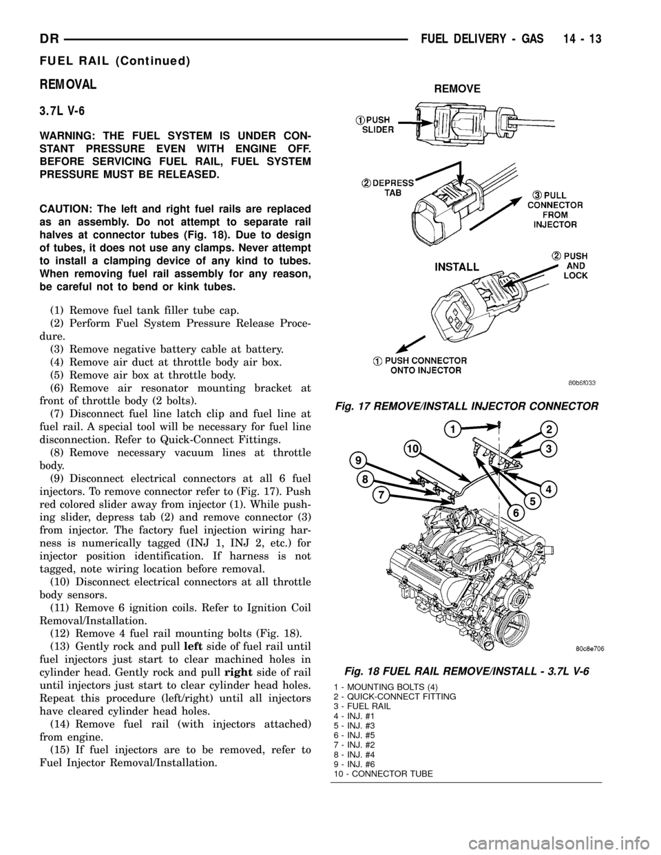
CAUTION: The left and right fuel rails are replaced
as an assembly. Do not attempt to separate rail
halves at connector tubes (Fig. 18). Due to design
of tubes, it does not use any clamps. Never attempt
to install a clamping device of any kind to tubes.
When removing fuel rail assembly for any reason,
be careful not to bend or kink tubes.
(1) Remove fuel tank filler tube cap.
(2) Perform Fuel System Pressure Release Proce-
dure.
(3) Remove negative battery cable at battery.
(4) Remove air duct at throttle body air box.
(5) Remove air box at throttle body.
(6) Remove air resonator mounting bracket at
front of throttle body (2 bolts).
(7) Disconnect fuel line latch clip and fuel line at
fuel rail. A special tool will be necessary for fuel line
disconnection. Refer to Quick-Connect Fittings.
(8) Remove necessary vacuum lines at throttle
body.
(9) Disconnect electrical connectors at all 6 fuel
injectors. To remove connector refer to (Fig. 17). Push
red colored slider away from injector (1). While push-
ing slider, depress tab (2) and remove connector (3)
from injector. The factory fuel injection wiring har-
ness is numerically tagged (INJ 1, INJ 2, etc.) for
injector position identification. If harness is not
tagged, note wiring location before removal.
(10) Disconnect electrical connectors at all throttle
body sensors.
(11) Remove 6 ignition coils. Refer to Ignition Coil
Removal/Installation.
(12) Remove 4 fuel rail mounting bolts (Fig. 18).
(13) Gently rock and pullleftside of fuel rail until
fuel injectors just start to clear machined holes in
cylinder head. Gently rock and pullrightside of rail
until injectors just start to clear cylinder head holes.
Repeat this procedure (left/right) until all injectors
have cleared cylinder head holes.
(14) Remove fuel rail (with injectors attached)
from engine.
(15) If fuel injectors are to be removed, refer to
Fuel Injector Removal/Installation.
Fig. 17 REMOVE/INSTALL INJECTOR CONNECTOR
Fig. 18 FUEL RAIL REMOVE/INSTALL - 3.7L V-6
1 - MOUNTING BOLTS (4)
2 - QUICK-CONNECT FITTING
3 - FUEL RAIL
4 - INJ. #1
5 - INJ. #3
6 - INJ. #5
7 - INJ. #2
8 - INJ. #4
9 - INJ. #6
10 - CONNECTOR TUBE
DRFUEL DELIVERY - GAS 14 - 13
FUEL RAIL (Continued)
Page 1583 of 2627
4.7L V-8
WARNING: THE FUEL SYSTEM IS UNDER CON-
STANT PRESSURE EVEN WITH ENGINE OFF.
BEFORE SERVICING FUEL RAIL, FUEL SYSTEM
PRESSURE MUST BE RELEASED.
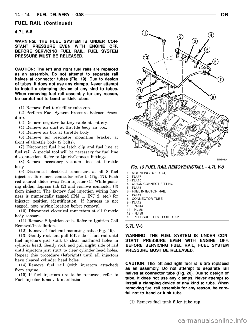
CAUTION: The left and right fuel rails are replaced
as an assembly. Do not attempt to separate rail
halves at connector tubes (Fig. 19). Due to design
of tubes, it does not use any clamps. Never attempt
to install a clamping device of any kind to tubes.
When removing fuel rail assembly for any reason,
be careful not to bend or kink tubes.
(1) Remove fuel tank filler tube cap.
(2) Perform Fuel System Pressure Release Proce-
dure.
(3) Remove negative battery cable at battery.
(4) Remove air duct at throttle body air box.
(5) Remove air box at throttle body.
(6) Remove air resonator mounting bracket at
front of throttle body (2 bolts).
(7) Disconnect fuel line latch clip and fuel line at
fuel rail. A special tool will be necessary for fuel line
disconnection. Refer to Quick-Connect Fittings.
(8) Remove necessary vacuum lines at throttle
body.
(9) Disconnect electrical connectors at all 8 fuel
injectors. To remove connector refer to (Fig. 17). Push
red colored slider away from injector (1). While push-
ing slider, depress tab (2) and remove connector (3)
from injector. The factory fuel injection wiring har-
ness is numerically tagged (INJ 1, INJ 2, etc.) for
injector position identification. If harness is not
tagged, note wiring location before removal.
(10) Disconnect electrical connectors at all throttle
body sensors.
(11) Remove 8 ignition coils. Refer to Ignition Coil
Removal/Installation.
(12) Remove 4 fuel rail mounting bolts (Fig. 19).
(13) Gently rock and pullleftside of fuel rail until
fuel injectors just start to clear machined holes in
cylinder head. Gently rock and pullrightside of rail
until injectors just start to clear cylinder head holes.
Repeat this procedure (left/right) until all injectors
have cleared cylinder head holes.
(14) Remove fuel rail (with injectors attached)
from engine.
(15) If fuel injectors are to be removed, refer to
Fuel Injector Removal/Installation.
5.7L V-8
WARNING: THE FUEL SYSTEM IS UNDER CON-
STANT PRESSURE EVEN WITH ENGINE OFF.
BEFORE SERVICING FUEL RAIL, FUEL SYSTEM
PRESSURE MUST BE RELEASED.
CAUTION: The left and right fuel rails are replaced
as an assembly. Do not attempt to separate rail
halves at connector tube (Fig. 20). Due to design of
tube, it does not use any clamps. Never attempt to
install a clamping device of any kind to tube. When
removing fuel rail assembly for any reason, be care-
ful not to bend or kink tube.
(1) Remove fuel tank filler tube cap.
Fig. 19 FUEL RAIL REMOVE/INSTALL - 4.7L V-8
1 - MOUNTING BOLTS (4)
2 - INJ.#7
3 - INJ.#5
4 - QUICK-CONNECT FITTING
5 - INJ.#3
6 - FUEL INJECTOR RAIL
7 - INJ.#1
8 - CONNECTOR TUBE
9 - INJ.#2
10 - INJ.#4
11 - INJ.#6
12 - INJ.#8
13 - PRESSURE TEST PORT CAP
14 - 14 FUEL DELIVERY - GASDR
FUEL RAIL (Continued)