1998 DODGE RAM 1500 length
[x] Cancel search: lengthPage 1479 of 2627
INTAKE/EXHAUST VALVES &
SEATS
DESCRIPTION
The valves are made of heat resistant steel, and
have chrome plated stems to prevent scuffing. The
intake and exhaust valves are both similar in head
diameter and overall length, but they have unique
face angles which makes them non-interchangeable.
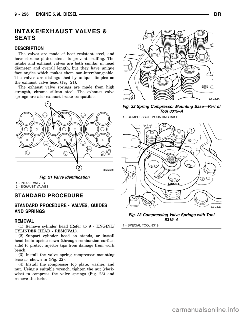
The valves are distinguished by unique dimples on
the exhaust valve head (Fig. 21).
The exhaust valve springs are made from high
strength, chrome silicon steel. The exhaust valve
springs are also exhaust brake compatible.
STANDARD PROCEDURE
STANDARD PROCEDURE - VALVES, GUIDES
AND SPRINGS
REMOVAL
(1) Remove cylinder head (Refer to 9 - ENGINE/
CYLINDER HEAD - REMOVAL).
(2) Support cylinder head on stands, or install
head bolts upside down (through combustion surface
side) to protect injector tips from damage from work
bench.
(3) Install the valve spring compressor mounting
base as shown in (Fig. 22).
(4) Install the compressor top plate, washer, and
nut. Using a suitable wrench, tighten the nut (clock-
wise) to compress the valve springs (Fig. 23) and
remove the locks.
Fig. 22 Spring Compressor Mounting BaseÐPart of
Tool 8319±A
1 - COMPRESSOR MOUNTING BASE
Fig. 23 Compressing Valve Springs with Tool
8319±A
1 - SPECIAL TOOL 8319
Fig. 21 Valve Identification
1 - INTAKE VALVES
2 - EXHAUST VALVES
9 - 256 ENGINE 5.9L DIESELDR
Page 1481 of 2627
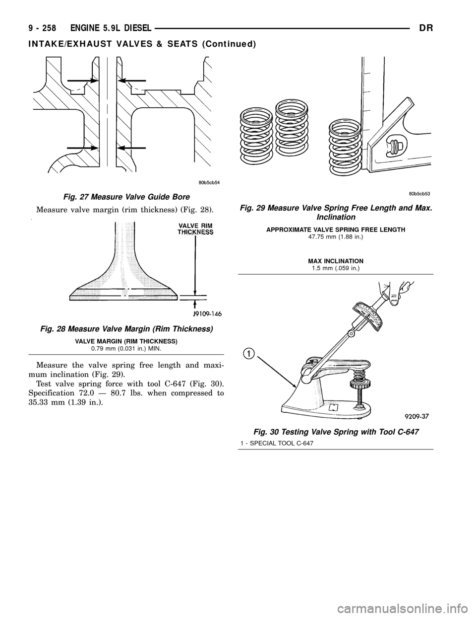
Measure valve margin (rim thickness) (Fig. 28).
Measure the valve spring free length and maxi-
mum inclination (Fig. 29).
Test valve spring force with tool C-647 (Fig. 30).
Specification 72.0 Ð 80.7 lbs. when compressed to
35.33 mm (1.39 in.).
Fig. 27 Measure Valve Guide Bore
Fig. 28 Measure Valve Margin (Rim Thickness)
VALVE MARGIN (RIM THICKNESS)
0.79 mm (0.031 in.) MIN.
Fig. 29 Measure Valve Spring Free Length and Max.
Inclination
APPROXIMATE VALVE SPRING FREE LENGTH
47.75 mm (1.88 in.)
MAX INCLINATION
1.5 mm (.059 in.)
Fig. 30 Testing Valve Spring with Tool C-647
1 - SPECIAL TOOL C-647
9 - 258 ENGINE 5.9L DIESELDR
INTAKE/EXHAUST VALVES & SEATS (Continued)
Page 1488 of 2627
(6) Use a drill, a fine grit Flex-hone and a mixture
of equal parts of mineral spirits and SAE 30W engine
oil to de-glaze the bores.
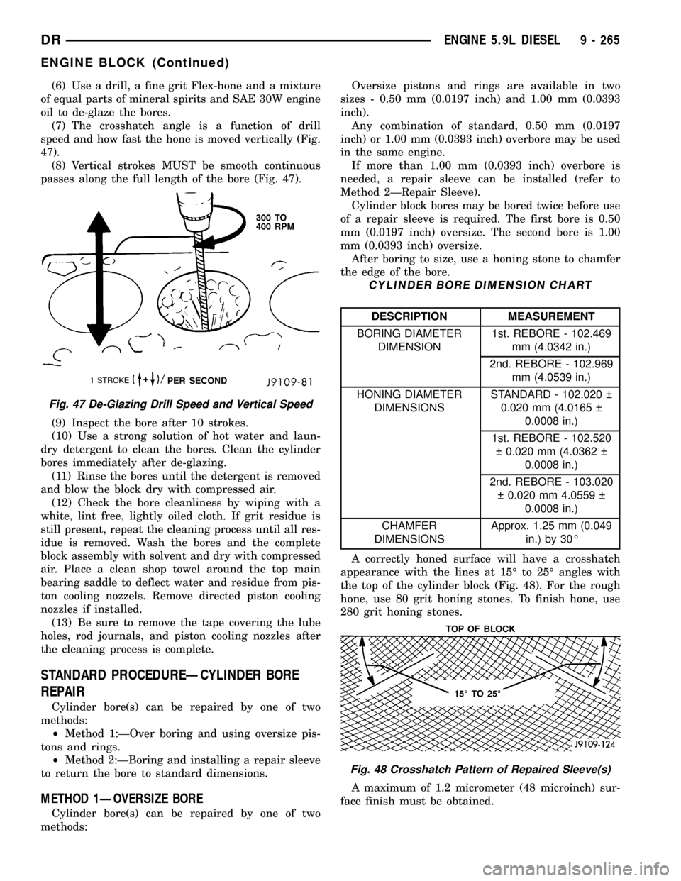
(7) The crosshatch angle is a function of drill
speed and how fast the hone is moved vertically (Fig.
47).
(8) Vertical strokes MUST be smooth continuous
passes along the full length of the bore (Fig. 47).
(9) Inspect the bore after 10 strokes.
(10) Use a strong solution of hot water and laun-
dry detergent to clean the bores. Clean the cylinder
bores immediately after de-glazing.
(11) Rinse the bores until the detergent is removed
and blow the block dry with compressed air.
(12) Check the bore cleanliness by wiping with a
white, lint free, lightly oiled cloth. If grit residue is
still present, repeat the cleaning process until all res-
idue is removed. Wash the bores and the complete
block assembly with solvent and dry with compressed
air. Place a clean shop towel around the top main
bearing saddle to deflect water and residue from pis-
ton cooling nozzels. Remove directed piston cooling
nozzles if installed.
(13) Be sure to remove the tape covering the lube
holes, rod journals, and piston cooling nozzles after
the cleaning process is complete.
STANDARD PROCEDUREÐCYLINDER BORE
REPAIR
Cylinder bore(s) can be repaired by one of two
methods:
²Method 1:ÐOver boring and using oversize pis-
tons and rings.
²Method 2:ÐBoring and installing a repair sleeve
to return the bore to standard dimensions.
METHOD 1ÐOVERSIZE BORE
Cylinder bore(s) can be repaired by one of two
methods:Oversize pistons and rings are available in two
sizes - 0.50 mm (0.0197 inch) and 1.00 mm (0.0393
inch).
Any combination of standard, 0.50 mm (0.0197
inch) or 1.00 mm (0.0393 inch) overbore may be used
in the same engine.
If more than 1.00 mm (0.0393 inch) overbore is
needed, a repair sleeve can be installed (refer to
Method 2ÐRepair Sleeve).
Cylinder block bores may be bored twice before use
of a repair sleeve is required. The first bore is 0.50
mm (0.0197 inch) oversize. The second bore is 1.00
mm (0.0393 inch) oversize.
After boring to size, use a honing stone to chamfer
the edge of the bore.
CYLINDER BORE DIMENSION CHART
DESCRIPTION MEASUREMENT
BORING DIAMETER
DIMENSION1st. REBORE - 102.469
mm (4.0342 in.)
2nd. REBORE - 102.969
mm (4.0539 in.)
HONING DIAMETER
DIMENSIONSSTANDARD - 102.020
0.020 mm (4.0165
0.0008 in.)
1st. REBORE - 102.520
0.020 mm (4.0362
0.0008 in.)
2nd. REBORE - 103.020
0.020 mm 4.0559
0.0008 in.)
CHAMFER
DIMENSIONSApprox. 1.25 mm (0.049
in.) by 30É
A correctly honed surface will have a crosshatch
appearance with the lines at 15É to 25É angles with
the top of the cylinder block (Fig. 48). For the rough
hone, use 80 grit honing stones. To finish hone, use
280 grit honing stones.
A maximum of 1.2 micrometer (48 microinch) sur-
face finish must be obtained.
Fig. 47 De-Glazing Drill Speed and Vertical Speed
Fig. 48 Crosshatch Pattern of Repaired Sleeve(s)
DRENGINE 5.9L DIESEL 9 - 265
ENGINE BLOCK (Continued)
Page 1502 of 2627
SOLID LIFTERS/TAPPETS
REMOVAL
NOTE: This procedure requires use of Miller Tool
8502 Tappet Replacement Kit.
(1) Remove camshaft (Refer to 9 - ENGINE/EN-
GINE BLOCK/CAMSHAFT & BEARINGS (IN
BLOCK) - REMOVAL).
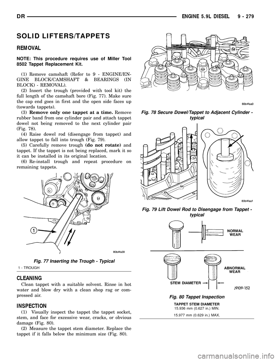
(2) Insert the trough (provided with tool kit) the
full length of the camshaft bore (Fig. 77). Make sure
the cap end goes in first and the open side faces up
(towards tappets).
(3)Remove only one tappet at a time.Remove
rubber band from one cylinder pair and attach tappet
dowel not being removed to the next cylinder pair
(Fig. 78).
(4) Raise dowel rod (disengage from tappet) and
allow tappet to fall into trough (Fig. 79).
(5) Carefully remove trough(do not rotate)and
tappet. If the tappet is not being replaced, mark it so
it can be installed in its original location.
(6) Re-install trough and repeat procedure on
remaining tappets.
CLEANING
Clean tappet with a suitable solvent. Rinse in hot
water and blow dry with a clean shop rag or com-
pressed air.
INSPECTION
(1) Visually inspect the tappet the tappet socket,
stem, and face for excessive wear, cracks, or obvious
damage (Fig. 80).
(2) Measure the tappet stem diameter. Replace the
tappet if it falls below the minimum size (Fig. 80).
Fig. 77 Inserting the Trough - Typical
1 - TROUGH
Fig. 78 Secure Dowel/Tappet to Adjacent Cylinder -
typical
Fig. 79 Lift Dowel Rod to Disengage from Tappet -
typical
Fig. 80 Tappet Inspection
TAPPET STEM DIAMETER
15.936 mm (0.627 in.) MIN.
15.977 mm (0.629 in.) MAX.
DRENGINE 5.9L DIESEL 9 - 279
Page 1503 of 2627
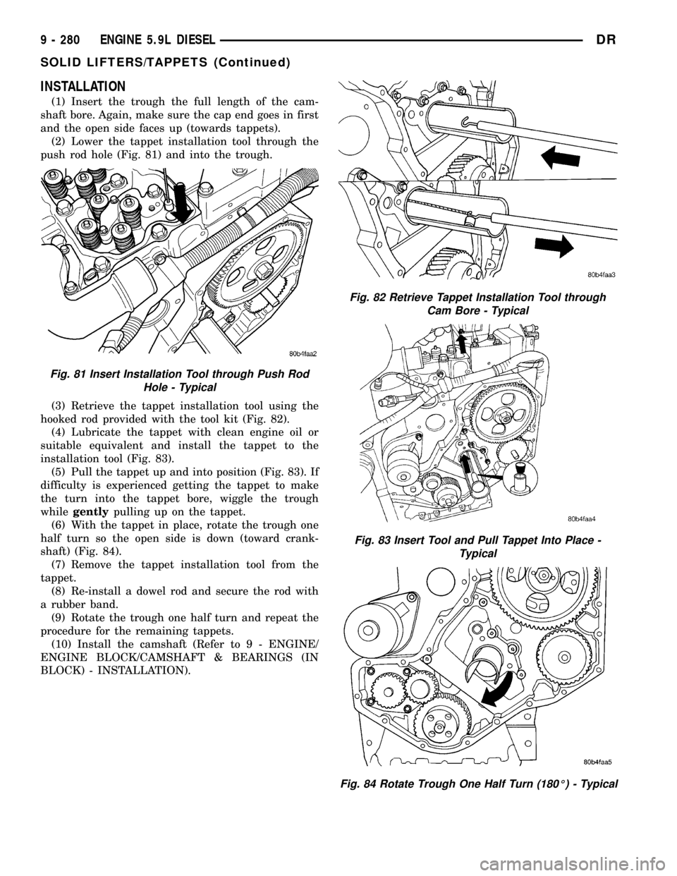
INSTALLATION
(1) Insert the trough the full length of the cam-
shaft bore. Again, make sure the cap end goes in first
and the open side faces up (towards tappets).
(2) Lower the tappet installation tool through the
push rod hole (Fig. 81) and into the trough.
(3) Retrieve the tappet installation tool using the
hooked rod provided with the tool kit (Fig. 82).
(4) Lubricate the tappet with clean engine oil or
suitable equivalent and install the tappet to the
installation tool (Fig. 83).
(5) Pull the tappet up and into position (Fig. 83). If
difficulty is experienced getting the tappet to make
the turn into the tappet bore, wiggle the trough
whilegentlypulling up on the tappet.
(6) With the tappet in place, rotate the trough one
half turn so the open side is down (toward crank-
shaft) (Fig. 84).
(7) Remove the tappet installation tool from the
tappet.
(8) Re-install a dowel rod and secure the rod with
a rubber band.
(9) Rotate the trough one half turn and repeat the
procedure for the remaining tappets.
(10) Install the camshaft (Refer to 9 - ENGINE/
ENGINE BLOCK/CAMSHAFT & BEARINGS (IN
BLOCK) - INSTALLATION).
Fig. 81 Insert Installation Tool through Push Rod
Hole - Typical
Fig. 82 Retrieve Tappet Installation Tool through
Cam Bore - Typical
Fig. 83 Insert Tool and Pull Tappet Into Place -
Typical
Fig. 84 Rotate Trough One Half Turn (180É) - Typical
9 - 280 ENGINE 5.9L DIESELDR
SOLID LIFTERS/TAPPETS (Continued)
Page 1512 of 2627
LUBRICATION
DESCRIPTION
NOTE: Refer to (Fig. 105) and (Fig. 106) for circuit
illustrations.
A gear driven gerotor type oil pump is mounted
behind the front gear cover in the lower right portion
on the engine.
OPERATION
A gerotor style oil pump draws oil from the crank-
case through the suction tube and delivers it through
the block where it enters the oil cooler cover and
pressure regulator valve. When oil pressure exceeds
517 kPa (75 PSI), the valve opens exposing the dump
port, which routes excess oil back to the oil pump.
At the same time, oil is directed to a cast in pas-
sage in the oil cooler cover, leading to the oil cooler
element. As the oil travels through the element
plates, it is cooled by engine coolant traveling past
the outside of the plates. It is then routed to the oil
filter head and through a full flow oil filter. If a
plugged filter is encountered, the filter by-pass valve
opens, allowing unfiltered oil to lubricate the engine.
This condition can be avoided by frequent oil and fil-
ter changes, per the maintenance schedules found in
the owners manual. The by-pass valve is calibrated
to open when it sees a pressure drop of more than
345 kPa (50 psi) across the oil filter.
The oil filter head then divides the oil between the
engine and the turbocharger. The turbocharger
receives filtered, cooled and pressurized oil through a
supply line from the filter head. The oil lubricates
the turbocharger and returns to the pan by way of a
drain tube connecting the bottom of the turbocharger
to a pressed in tube in the cylinder block.
Oil is then carried across the block to an angle
drilling which intersects the main oil rifle. The main
oil rifle runs the length of the block and delivers oil
to the crankshaft main journals and valve train. Oil
travels to the crankshaft through a series of transfer
drillings (one for each main bearing) and lubricates a
groove in the main bearing upper shell. From there
another drilling feeds the camshaft main journals.The saddle jet piston cooling nozzles are also sup-
plied by the main bearing upper shell. J-jet piston
cooling nozzles are supplied by a separate oil rifle.
Plugs are used in place of saddle jets when J-jets are
used. J-jet hole locations are plugged when saddle jet
cooling nozzles are used. Crankshaft internal cross-
drillings supply oil to the connecting rod journals.
Another series of transfer drillings intersecting the
main oil rifle supply the valve train components. Oil
travels up the drilling, through a hole in the head
gasket, and through a drilling in the cylinder head
(one per cylinder), where it enters the rocker arm
pedestal and is divided between the intake and
exhaust rocker arm. Oil travels up and around the
rocker arm mounting bolt, and lubricates the rocker
shaft by cross drillings that intersect the mounting
bolt hole. Grooves at both ends of the rocker shaft
supply oil through the rocker arm where the oil trav-
els to the push rod and socket balls (Fig. 105) and
(Fig. 106).
DIAGNOSIS AND TESTINGÐENGINE OIL
PRESSURE
(1) Remove the 1/8 npt plug from the top of the oil
filter housing.
(2) Install Oil Pressure Line and Gauge Tool
C-3292 with a suitable adapter.
(3) Start engine and warm to operating tempera-
ture.
(4) Record engine oil pressure and compare with
engine oil pressure chart.
CAUTION: If engine oil pressure is zero at idle, DO
NOT RUN THE ENGINE.
Engine Oil Pressure (MIN)
At Idle 68.9 kPa (10 psi)
At 2500 rpm 206.9 kPa (30 psi)
If minimum engine oil pressure is below these
ranges, (Refer to 9 - ENGINE - DIAGNOSIS AND
TESTING).
(5) Remove oil pressure gauge and install the 1/8
npt plug.
DRENGINE 5.9L DIESEL 9 - 289
Page 1626 of 2627
FUEL LEVEL SENDING UNIT /
SENSOR
DESCRIPTION
The fuel gauge sending unit (fuel level sensor) is
attached to the side of the fuel tank module. The
sending unit consists of a float, an arm, and a vari-
able resistor track (card).
OPERATION
The fuel tank module on diesel powered models
has 2 different circuits (wires). Two of these circuits
are used at the fuel gauge sending unit for fuel
gauge operation. The diesel engine does not have a
fuel tank module mounted electric fuel pump. The
electric fuel pump (fuel transfer pump) is mounted to
the engine.
For Fuel Gauge Operation:A constant input
voltage source of about 12 volts (battery voltage) is
supplied to the resistor track on the fuel gauge send-
ing unit. This is fed directly from the Engine Control
Module (ECM).NOTE: For diagnostic purposes,
this 12V power source can only be verified with
the circuit opened (fuel tank module electrical
connector unplugged). With the connectors
plugged, output voltages will vary from about .6
volts at FULL, to about 7.0 volts at EMPTY.The
resistor track is used to vary the voltage (resistance)
depending on fuel tank float level. As fuel level
increases, the float and arm move up, which
decreases voltage. As fuel level decreases, the float
and arm move down, which increases voltage. The
varied voltage signal is returned back to the ECM
through the sensor return circuit.
Both of the electrical circuits between the fuel
gauge sending unit and the ECM are hard-wired (not
multi-plexed). After the voltage signal is sent from
the resistor track, and back to the ECM, the ECM
will interpret the resistance (voltage) data and send
a message across the multi-plex bus circuits to the
instrument panel cluster. Here it is translated into
the appropriate fuel gauge level reading. Refer to
Instrument Panel for additional information.
REMOVAL
REMOVAL/INSTALLATION
For diesel removal and installation procedures,
refer to the gas section of Fuel System/Fuel Delivery.
See Fuel Level Sending Unit/Sensor Removal/Instal-
lation.
FUEL LINES
DESCRIPTION
Low-Pressure Lines Are:
²the fuel supply line from fuel tank to fuel trans-
fer (lift) pump.
²the fuel return line back to fuel tank.
²the fuel drain (manifold) line at rear of cylinder
head.
²the fuel supply line from fuel filter to fuel injec-
tion pump.
²the fuel injection pump return line.
High-Pressure Lines Are:
²the fuel line from fuel injection pump to fuel
rail.
²the 6 fuel lines from fuel rail up to injector con-
nector tubes
WARNING: HIGH-PRESSURE FUEL LINES DELIVER
DIESEL FUEL UNDER EXTREME PRESSURE FROM
THE INJECTION PUMP TO THE FUEL INJECTORS.
THIS MAY BE AS HIGH AS 160,000 KPA (23,206
PSI). USE EXTREME CAUTION WHEN INSPECTING
FOR HIGH-PRESSURE FUEL LEAKS. INSPECT FOR
HIGH-PRESSURE FUEL LEAKS WITH A SHEET OF
CARDBOARD. HIGH FUEL INJECTION PRESSURE
CAN CAUSE PERSONAL INJURY IF CONTACT IS
MADE WITH THE SKIN.
OPERATION
High-Pressure Lines
CAUTION: The high-pressure fuel lines must be
held securely in place in their holders. The lines
cannot contact each other or other components. Do
not attempt to weld high-pressure fuel lines or to
repair lines that are damaged. If lines are ever
kinked or bent, they must be replaced. Use only the
recommended lines when replacement of high-pres-
sure fuel line is necessary.
High-pressure fuel lines deliver fuel (under pres-
sure) of up to approximately 160,000 kPa (23,206
PSI) from the injection pump to the fuel injectors.
The lines expand and contract from the high-pres-
sure fuel pulses generated during the injection pro-
cess. All high-pressure fuel lines are of the same
length and inside diameter. Correct high-pressure
fuel line usage and installation is critical to smooth
engine operation.
DRFUEL DELIVERY - DIESEL 14 - 57
Page 1629 of 2627
INSTALLATION
All high-pressure fuel lines are of the same length
and inside diameter. Correct high-pressure fuel line
usage and installation is critical to smooth engine
operation.
CAUTION: Anytime a high-pressure line is removed
from the engine, its fuel connector nut at the cylin-
der head must first be retorqued. Refer to Torque
Specifications.
(1) Tighten fuel lines at high pressure injector con-
nector. Refer to Torque Specifications.
(2) Position fuel line support clamp(s) to fuel
line(s). Install clamp nuts/bolts and tighten finger
tight.
(3) Position proper fuel line to proper injector on
engine. Tighten fittings hand tight at both ends of
line.
(4) Tighten fuel lines at fuel rail. Refer to Torque
Specifications.
(5) Tighten clamp/support nuts and bolts. Refer to
Torque Specifications.
(6) Install engine lifting bracket and bolt. Refer to
Torque Specifications.
(7) If fuel line at either #1 or #2 cylinder has been
replaced, install intake manifold air heater elements
to top of intake manifold. Refer to Intake Air Heater
Removal / Installation for procedures.
(8) If fuel line at #6 cylinder has been replaced, tilt
metal bracket upward and tighten 2 bolts at rear of
cylinder head. Refer to Torque Specifications.
(9) Install remaining fuel line support clamps and
bracket bolts at intake manifold. Refer to Torque
Specifications.
(10) Connect both negative battery cables to both
batteries.
(11) Prime fuel system. Refer to Fuel System
Priming.
(12) Check lines/fittings for leaks.
FUEL PRESSURE SENSOR
DESCRIPTION
The fuel pressure sensor is mounted vertically near
the top/center of the fuel rail.
OPERATION
The fuel pressure sensor monitors actual high-
pressure within the fuel rail. An output signal from
this sensor (relating to fuel pressure) is sent to the
Engine Control Module (ECM).
REMOVAL
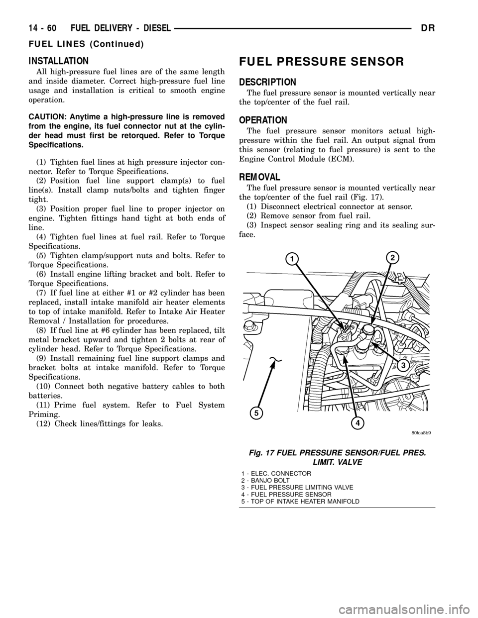
The fuel pressure sensor is mounted vertically near
the top/center of the fuel rail (Fig. 17).
(1) Disconnect electrical connector at sensor.
(2) Remove sensor from fuel rail.
(3) Inspect sensor sealing ring and its sealing sur-
face.
Fig. 17 FUEL PRESSURE SENSOR/FUEL PRES.
LIMIT. VALVE
1 - ELEC. CONNECTOR
2 - BANJO BOLT
3 - FUEL PRESSURE LIMITING VALVE
4 - FUEL PRESSURE SENSOR
5 - TOP OF INTAKE HEATER MANIFOLD
14 - 60 FUEL DELIVERY - DIESELDR
FUEL LINES (Continued)