1998 DODGE RAM 1500 length
[x] Cancel search: lengthPage 1253 of 2627
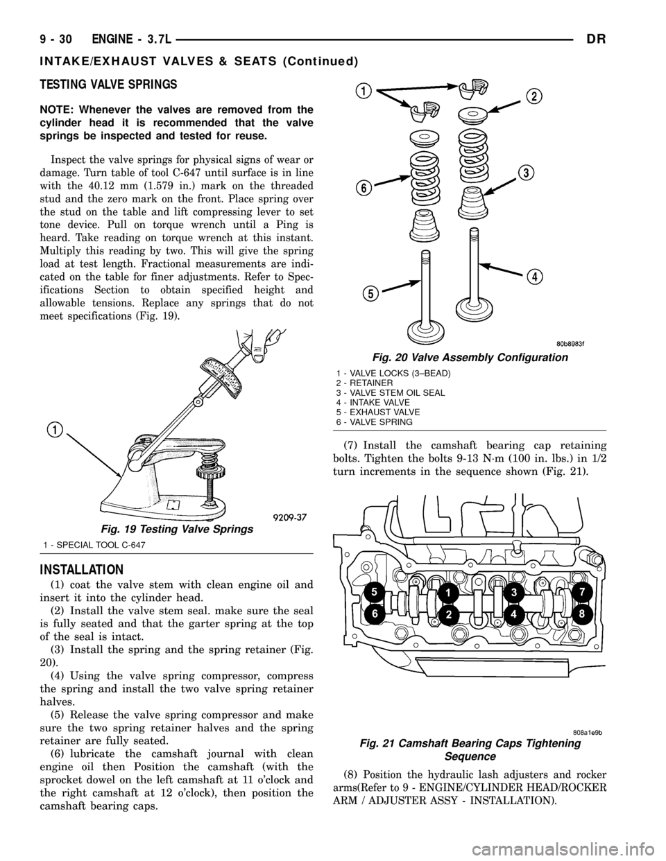
TESTING VALVE SPRINGS
NOTE: Whenever the valves are removed from the
cylinder head it is recommended that the valve
springs be inspected and tested for reuse.
Inspect the valve springs for physical signs of wear or
damage. Turn table of tool C-647 until surface is in line
with the 40.12 mm (1.579 in.) mark on the threaded
stud and the zero mark on the front. Place spring over
the stud on the table and lift compressing lever to set
tone device. Pull on torque wrench until a Ping is
heard. Take reading on torque wrench at this instant.
Multiply this reading by two. This will give the spring
load at test length. Fractional measurements are indi-
cated on the table for finer adjustments. Refer to Spec-
ifications Section to obtain specified height and
allowable tensions. Replace any springs that do not
meet specifications (Fig. 19).
INSTALLATION
(1) coat the valve stem with clean engine oil and
insert it into the cylinder head.
(2) Install the valve stem seal. make sure the seal
is fully seated and that the garter spring at the top
of the seal is intact.
(3) Install the spring and the spring retainer (Fig.
20).
(4) Using the valve spring compressor, compress
the spring and install the two valve spring retainer
halves.
(5) Release the valve spring compressor and make
sure the two spring retainer halves and the spring
retainer are fully seated.
(6) lubricate the camshaft journal with clean
engine oil then Position the camshaft (with the
sprocket dowel on the left camshaft at 11 o'clock and
the right camshaft at 12 o'clock), then position the
camshaft bearing caps.(7) Install the camshaft bearing cap retaining
bolts. Tighten the bolts 9-13 N´m (100 in. lbs.) in 1/2
turn increments in the sequence shown (Fig. 21).
(8)
Position the hydraulic lash adjusters and rocker
arms(Refer to 9 - ENGINE/CYLINDER HEAD/ROCKER
ARM / ADJUSTER ASSY - INSTALLATION).
Fig. 19 Testing Valve Springs
1 - SPECIAL TOOL C-647
Fig. 20 Valve Assembly Configuration
1 - VALVE LOCKS (3±BEAD)
2 - RETAINER
3 - VALVE STEM OIL SEAL
4 - INTAKE VALVE
5 - EXHAUST VALVE
6 - VALVE SPRING
Fig. 21 Camshaft Bearing Caps Tightening
Sequence
9 - 30 ENGINE - 3.7LDR
INTAKE/EXHAUST VALVES & SEATS (Continued)
Page 1324 of 2627
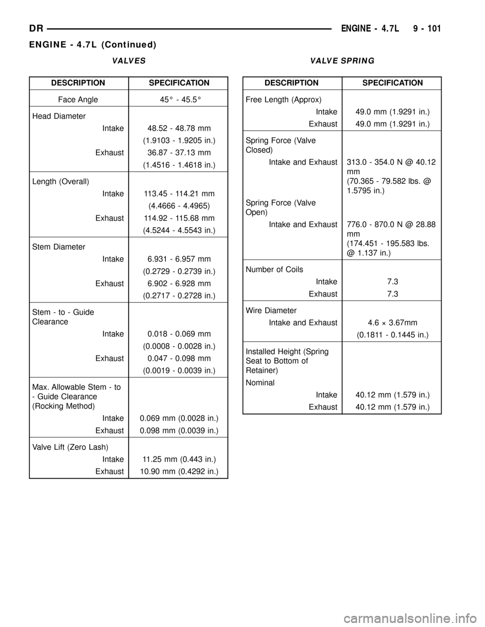
VALVES
DESCRIPTION SPECIFICATION
Face Angle 45É - 45.5É
Head Diameter
Intake 48.52 - 48.78 mm
(1.9103 - 1.9205 in.)
Exhaust 36.87 - 37.13 mm
(1.4516 - 1.4618 in.)
Length (Overall)
Intake 113.45 - 114.21 mm
(4.4666 - 4.4965)
Exhaust 114.92 - 115.68 mm
(4.5244 - 4.5543 in.)
Stem Diameter
Intake 6.931 - 6.957 mm
(0.2729 - 0.2739 in.)
Exhaust 6.902 - 6.928 mm
(0.2717 - 0.2728 in.)
Stem - to - Guide
Clearance
Intake 0.018 - 0.069 mm
(0.0008 - 0.0028 in.)
Exhaust 0.047 - 0.098 mm
(0.0019 - 0.0039 in.)
Max. Allowable Stem - to
- Guide Clearance
(Rocking Method)
Intake 0.069 mm (0.0028 in.)
Exhaust 0.098 mm (0.0039 in.)
Valve Lift (Zero Lash)
Intake 11.25 mm (0.443 in.)
Exhaust 10.90 mm (0.4292 in.)
VALVE SPRING
DESCRIPTION SPECIFICATION
Free Length (Approx)
Intake 49.0 mm (1.9291 in.)
Exhaust 49.0 mm (1.9291 in.)
Spring Force (Valve
Closed)
Intake and Exhaust 313.0 - 354.0 N @ 40.12
mm
(70.365 - 79.582 lbs. @
1.5795 in.)
Spring Force (Valve
Open)
Intake and Exhaust 776.0 - 870.0 N @ 28.88
mm
(174.451 - 195.583 lbs.
@ 1.137 in.)
Number of Coils
Intake 7.3
Exhaust 7.3
Wire Diameter
Intake and Exhaust 4.6 ý 3.67mm
(0.1811 - 0.1445 in.)
Installed Height (Spring
Seat to Bottom of
Retainer)
Nominal
Intake 40.12 mm (1.579 in.)
Exhaust 40.12 mm (1.579 in.)
DRENGINE - 4.7L 9 - 101
ENGINE - 4.7L (Continued)
Page 1347 of 2627
REMOVAL
NOTE: The cylinder heads must be removed in
order to perform this procedure.
(1) Remove rocker arms and lash adjusters(Refer
to 9 - ENGINE/CYLINDER HEAD/ROCKER ARM /
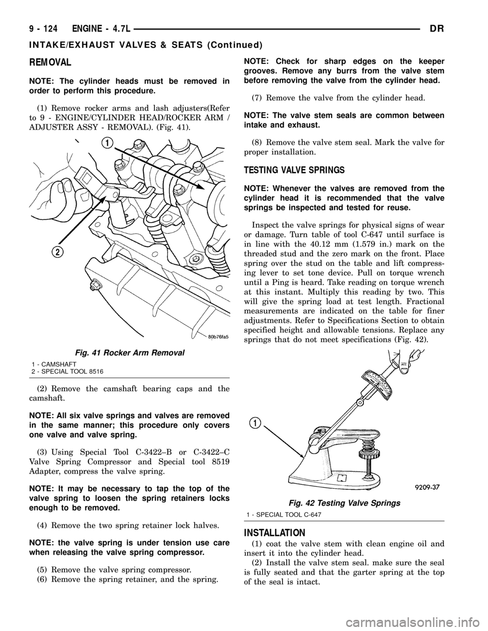
ADJUSTER ASSY - REMOVAL). (Fig. 41).
(2) Remove the camshaft bearing caps and the
camshaft.
NOTE: All six valve springs and valves are removed
in the same manner; this procedure only covers
one valve and valve spring.
(3) Using Special Tool C-3422±B or C-3422±C
Valve Spring Compressor and Special tool 8519
Adapter, compress the valve spring.
NOTE: It may be necessary to tap the top of the
valve spring to loosen the spring retainers locks
enough to be removed.
(4) Remove the two spring retainer lock halves.
NOTE: the valve spring is under tension use care
when releasing the valve spring compressor.
(5) Remove the valve spring compressor.
(6) Remove the spring retainer, and the spring.NOTE: Check for sharp edges on the keeper
grooves. Remove any burrs from the valve stem
before removing the valve from the cylinder head.
(7) Remove the valve from the cylinder head.
NOTE: The valve stem seals are common between
intake and exhaust.
(8) Remove the valve stem seal. Mark the valve for
proper installation.
TESTING VALVE SPRINGS
NOTE: Whenever the valves are removed from the
cylinder head it is recommended that the valve
springs be inspected and tested for reuse.
Inspect the valve springs for physical signs of wear
or damage. Turn table of tool C-647 until surface is
in line with the 40.12 mm (1.579 in.) mark on the
threaded stud and the zero mark on the front. Place
spring over the stud on the table and lift compress-
ing lever to set tone device. Pull on torque wrench
until a Ping is heard. Take reading on torque wrench
at this instant. Multiply this reading by two. This
will give the spring load at test length. Fractional
measurements are indicated on the table for finer
adjustments. Refer to Specifications Section to obtain
specified height and allowable tensions. Replace any
springs that do not meet specifications (Fig. 42).
INSTALLATION
(1) coat the valve stem with clean engine oil and
insert it into the cylinder head.
(2) Install the valve stem seal. make sure the seal
is fully seated and that the garter spring at the top
of the seal is intact.
Fig. 41 Rocker Arm Removal
1 - CAMSHAFT
2 - SPECIAL TOOL 8516
Fig. 42 Testing Valve Springs
1 - SPECIAL TOOL C-647
9 - 124 ENGINE - 4.7LDR
INTAKE/EXHAUST VALVES & SEATS (Continued)
Page 1415 of 2627
(31)Install the air cleaner resonator and duct work..
(32) Add engine oil to crankcase (Refer to LUBRI-
CATION & MAINTENANCE/FLUID TYPES - SPEC-
IFICATIONS).
(33) Fill cooling system (Refer to 7 - COOLING -
STANDARD PROCEDURE).
(34) Connect battery negative cable.
(35) Start engine and inspect for leaks.
(36) Road test vehicle.
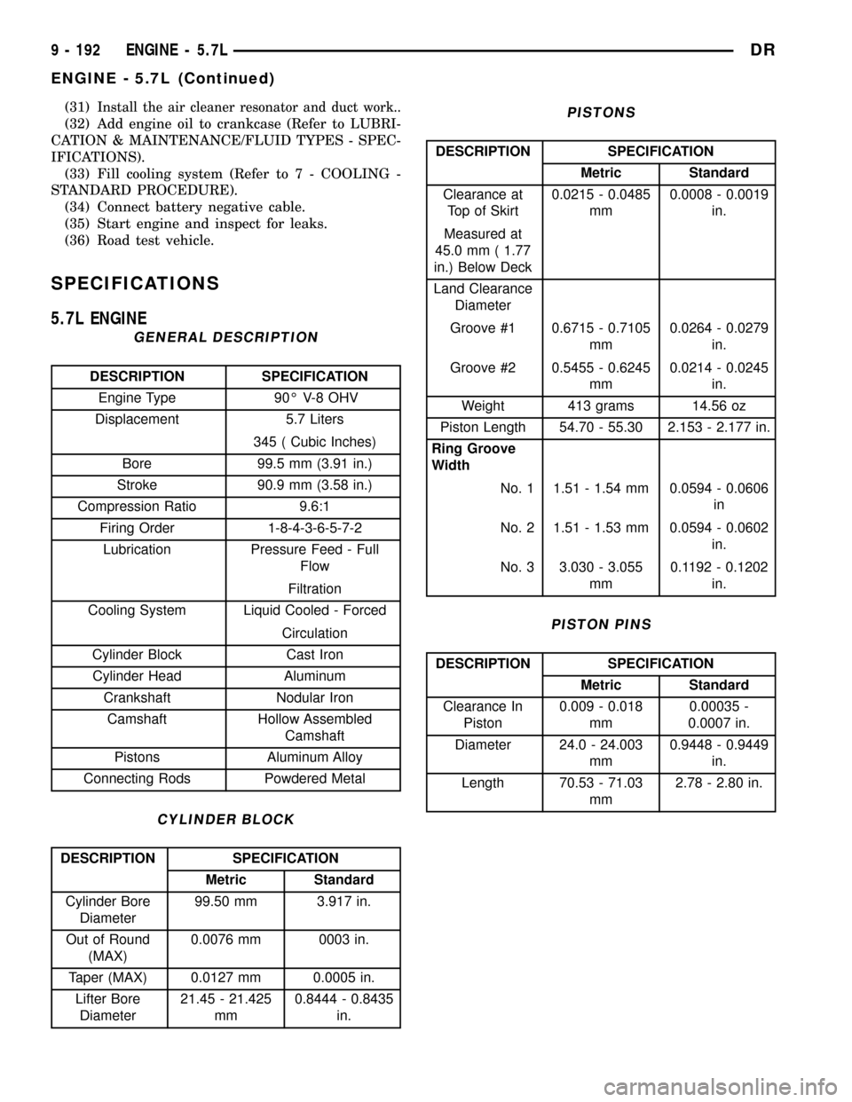
SPECIFICATIONS
5.7L ENGINE
GENERAL DESCRIPTION
DESCRIPTION SPECIFICATION
Engine Type 90É V-8 OHV
Displacement 5.7 Liters
345 ( Cubic Inches)
Bore 99.5 mm (3.91 in.)
Stroke 90.9 mm (3.58 in.)
Compression Ratio 9.6:1
Firing Order 1-8-4-3-6-5-7-2
Lubrication Pressure Feed - Full
Flow
Filtration
Cooling System Liquid Cooled - Forced
Circulation
Cylinder Block Cast Iron
Cylinder Head Aluminum
Crankshaft Nodular Iron
Camshaft Hollow Assembled
Camshaft
Pistons Aluminum Alloy
Connecting Rods Powdered Metal
CYLINDER BLOCK
DESCRIPTION SPECIFICATION
Metric Standard
Cylinder Bore
Diameter99.50 mm 3.917 in.
Out of Round
(MAX)0.0076 mm 0003 in.
Taper (MAX) 0.0127 mm 0.0005 in.
Lifter Bore
Diameter21.45 - 21.425
mm0.8444 - 0.8435
in.
PISTONS
DESCRIPTION SPECIFICATION
Metric Standard
Clearance at
Top of Skirt0.0215 - 0.0485
mm0.0008 - 0.0019
in.
Measured at
45.0 mm ( 1.77
in.) Below Deck
Land Clearance
Diameter
Groove #1 0.6715 - 0.7105
mm0.0264 - 0.0279
in.
Groove #2 0.5455 - 0.6245
mm0.0214 - 0.0245
in.
Weight 413 grams 14.56 oz
Piston Length 54.70 - 55.30 2.153 - 2.177 in.
Ring Groove
Width
No. 1 1.51 - 1.54 mm 0.0594 - 0.0606
in
No. 2 1.51 - 1.53 mm 0.0594 - 0.0602
in.
No. 3 3.030 - 3.055
mm0.1192 - 0.1202
in.
PISTON PINS
DESCRIPTION SPECIFICATION
Metric Standard
Clearance In
Piston0.009 - 0.018
mm0.00035 -
0.0007 in.
Diameter 24.0 - 24.003
mm0.9448 - 0.9449
in.
Length 70.53 - 71.03
mm2.78 - 2.80 in.
9 - 192 ENGINE - 5.7LDR
ENGINE - 5.7L (Continued)
Page 1417 of 2627
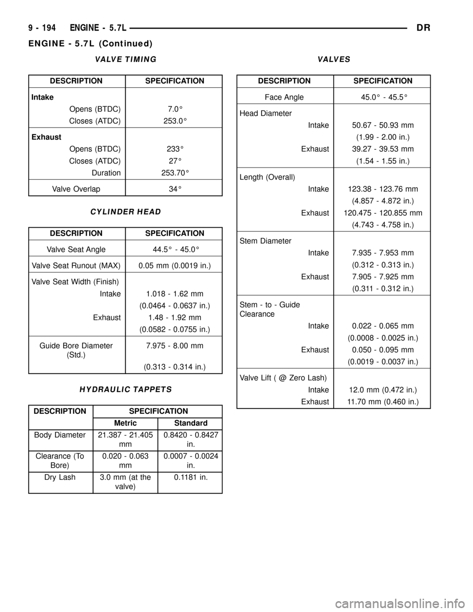
VALVE TIMING
DESCRIPTION SPECIFICATION
Intake
Opens (BTDC) 7.0É
Closes (ATDC) 253.0É
Exhaust
Opens (BTDC) 233É
Closes (ATDC) 27É
Duration 253.70É
Valve Overlap 34É
CYLINDER HEAD
DESCRIPTION SPECIFICATION
Valve Seat Angle 44.5É - 45.0É
Valve Seat Runout (MAX) 0.05 mm (0.0019 in.)
Valve Seat Width (Finish)
Intake 1.018 - 1.62 mm
(0.0464 - 0.0637 in.)
Exhaust 1.48 - 1.92 mm
(0.0582 - 0.0755 in.)
Guide Bore Diameter
(Std.)7.975 - 8.00 mm
(0.313 - 0.314 in.)
HYDRAULIC TAPPETS
DESCRIPTION SPECIFICATION
Metric Standard
Body Diameter 21.387 - 21.405
mm0.8420 - 0.8427
in.
Clearance (To
Bore)0.020 - 0.063
mm0.0007 - 0.0024
in.
Dry Lash 3.0 mm (at the
valve)0.1181 in.
VALVES
DESCRIPTION SPECIFICATION
Face Angle 45.0É - 45.5É
Head Diameter
Intake 50.67 - 50.93 mm
(1.99 - 2.00 in.)
Exhaust 39.27 - 39.53 mm
(1.54 - 1.55 in.)
Length (Overall)
Intake 123.38 - 123.76 mm
(4.857 - 4.872 in.)
Exhaust 120.475 - 120.855 mm
(4.743 - 4.758 in.)
Stem Diameter
Intake 7.935 - 7.953 mm
(0.312 - 0.313 in.)
Exhaust 7.905 - 7.925 mm
(0.311 - 0.312 in.)
Stem - to - Guide
Clearance
Intake 0.022 - 0.065 mm
(0.0008 - 0.0025 in.)
Exhaust 0.050 - 0.095 mm
(0.0019 - 0.0037 in.)
Valve Lift ( @ Zero Lash)
Intake 12.0 mm (0.472 in.)
Exhaust 11.70 mm (0.460 in.)
9 - 194 ENGINE - 5.7LDR
ENGINE - 5.7L (Continued)
Page 1433 of 2627

INSTALLATION
(1) Throughly clean all gasket resdue from the
engine block.
(2) Use extream care and clean all gasket resdue
from the retainer.
(3) Position the gasket onto the retainer.
(4) Position the retainer onto the engine block.
(5) Install the retainer mounting bolts. Tighten the
bolts to 15 N´m (132 in. lbs.) using a crisscross pat-
tern, starting with the bolt on the lower right.
(6) Install a new rear seal(Refer to 9 - ENGINE/
ENGINE BLOCK/CRANKSHAFT OIL SEAL - REAR
- INSTALLATION).
(7) Install the oil pan (Refer to 9 - ENGINE/LU-
BRICATION/OIL PAN - INSTALLATION).
(8) Install the drive plate / flywheel.
(9) Install the transmission.
(10) Check and verify engine oil level.
(11) Start engine and check for leaks.
FLEX PLATE
REMOVAL
(1) Remove the transmission.
(2) Remove the bolts and flexplate.
INSTALLATION
(1) Position the flexplate or flywheel onto the
crankshaft and install the bolts hand tight.
(2)For automatic transmissions:Tighten the
flexplate retaining bolts to 95 N´m (70 ft. lbs.).
(3)For manual transmissions:Tighten the fly-
wheel retaining bolts to 75 N´m (55 ft. lbs.).
(4) Install the transmission.
HYDRAULIC TAPPETS
DIAGNOSIS AND TESTING - HYDRAULIC
TAPPETS
Before disassembling any part of the engine to cor-
rect tappet noise, check the oil pressure. If vehicle
has no oil pressure gauge, install a reliable gauge at
the pressure sending-unit. The pressure should be
between 207-552 kPa (30-70 psi) at 3,000 RPM.
Check the oil level after the engine reaches normal
operating temperature. Allow 5 minutes to stabilize
oil level, check dipstick. The oil level in the pan
should never be above the FULL mark or below the
ADD OIL mark on dipstick. Either of these two con-
ditions could be responsible for noisy tappets.
OIL LEVEL
HIGH
If oil level is above the FULL mark, it is possible
for the connecting rods to dip into the oil. With the
engine running, this condition could create foam in
the oil pan. Foam in oil pan would be fed to the
hydraulic tappets by the oil pump causing them to
lose length and allow valves to seat noisily.
LOW
Low oil level may allow oil pump to take in air. When
air is fed to the tappets, they lose length, which allows
valves to seat noisily. Any leaks on intake side of oil
pump through which air can be drawn will create the
same tappet action. Check the lubrication system from
the intake strainer to the pump cover, including the
relief valve retainer cap. When tappet noise is due to
aeration, it may be intermittent or constant, and usu-
ally more than one tappet will be noisy. When oil level
and leaks have been corrected, operate the engine at
fast idle. Run engine for a sufficient time to allow all of
the air inside the tappets to be bled out.
TAPPET NOISE DIAGNOSIS
(1) To determine source of tappet noise, operate
engine at idle with cylinder head covers removed.
(2) Feel each valve spring or rocker arm to detect
noisy tappet. The noisy tappet will cause the affected
spring and/or rocker arm to vibrate or feel rough in
operation.
NOTE: Worn valve guides or cocked springs are
sometimes mistaken for noisy tappets. If such is
the case, noise may be dampened by applying side
thrust on the valve spring. If noise is not apprecia-
bly reduced, it can be assumed the noise is in the
tappet. Inspect the rocker arm push rod sockets
and push rod ends for wear.
(3)
Valve tappet noise ranges from light noise to a
heavy click. A light noise is usually caused by excessive
leak-down around the unit plunger, or by the plunger
partially sticking in the tappet body cylinder. The tap-
pet should be replaced. A heavy click is caused by a tap-
pet check valve not seating, or by foreign particles
wedged between the plunger and the tappet body. This
will cause the plunger to stick in the down position.
This heavy click will be accompanied by excessive clear-
ance between the valve stem and rocker arm as valve
closes. In either case, tappet assembly should be
removed for inspection and cleaning.
(4) The valve train generates a noise very much
like a light tappet noise during normal operation.
Care must be taken to ensure that tappets are mak-
ing the noise. If more than one tappet seems to be
noisy, it's probably not the tappets.
9 - 210 ENGINE - 5.7LDR
CRANKSHAFT REAR OIL SEAL RETAINER (Continued)
Page 1465 of 2627
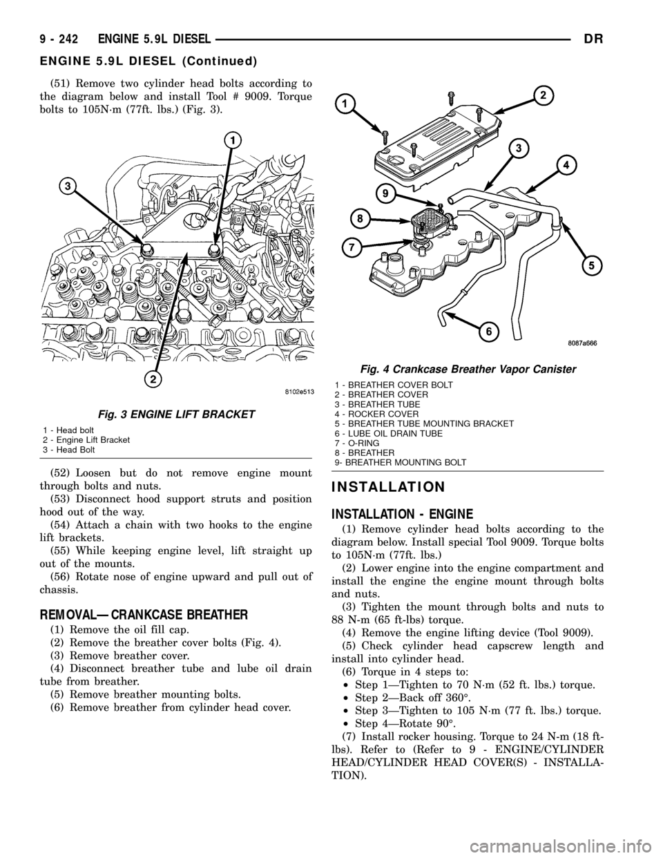
(51) Remove two cylinder head bolts according to
the diagram below and install Tool # 9009. Torque
bolts to 105N´m (77ft. lbs.) (Fig. 3).
(52) Loosen but do not remove engine mount
through bolts and nuts.
(53) Disconnect hood support struts and position
hood out of the way.
(54) Attach a chain with two hooks to the engine
lift brackets.
(55) While keeping engine level, lift straight up
out of the mounts.
(56) Rotate nose of engine upward and pull out of
chassis.
REMOVALÐCRANKCASE BREATHER
(1) Remove the oil fill cap.
(2) Remove the breather cover bolts (Fig. 4).
(3) Remove breather cover.
(4) Disconnect breather tube and lube oil drain
tube from breather.
(5) Remove breather mounting bolts.
(6) Remove breather from cylinder head cover.
INSTALLATION
INSTALLATION - ENGINE
(1) Remove cylinder head bolts according to the
diagram below. Install special Tool 9009. Torque bolts
to 105N´m (77ft. lbs.)
(2) Lower engine into the engine compartment and
install the engine the engine mount through bolts
and nuts.
(3) Tighten the mount through bolts and nuts to
88 N-m (65 ft-lbs) torque.
(4) Remove the engine lifting device (Tool 9009).
(5) Check cylinder head capscrew length and
install into cylinder head.
(6) Torque in 4 steps to:
²Step 1ÐTighten to 70 N´m (52 ft. lbs.) torque.
²Step 2ÐBack off 360É.
²Step 3ÐTighten to 105 N´m (77 ft. lbs.) torque.
²Step 4ÐRotate 90É.
(7) Install rocker housing. Torque to 24 N-m (18 ft-
lbs). Refer to (Refer to 9 - ENGINE/CYLINDER
HEAD/CYLINDER HEAD COVER(S) - INSTALLA-
TION).
Fig. 3 ENGINE LIFT BRACKET
1 - Head bolt
2 - Engine Lift Bracket
3 - Head Bolt
Fig. 4 Crankcase Breather Vapor Canister
1 - BREATHER COVER BOLT
2 - BREATHER COVER
3 - BREATHER TUBE
4 - ROCKER COVER
5 - BREATHER TUBE MOUNTING BRACKET
6 - LUBE OIL DRAIN TUBE
7 - O-RING
8 - BREATHER
9- BREATHER MOUNTING BOLT
9 - 242 ENGINE 5.9L DIESELDR
ENGINE 5.9L DIESEL (Continued)
Page 1475 of 2627

CLEANINGÐPUSHRODS
Clean the pushrods in a suitable solvent. Rinse in
hot water and blow dry with compressed air. If nec-
essary, use a wire brush or wheel to remove stubborn
deposits.
INSPECTION
INSPECTION - CYLINDER HEAD
Inspect the cylinder head for cracks in the combus-
tion surface. Pressure test any cylinder head that is
visibly cracked. A cylinder head that is cracked
between the injector bore and valve seat can be pres-
sure tested and reused if OK; however, if the crack
extendsintothe valve seat insert bore, the cylinder
headmustbe replaced.
Visually inspect the cylinder block and head com-
bustion surfaces for localized dips or imperfections.
Check the cylinder head and block combustion sur-
faces for overall out-of-flatness. If either the visual or
manual inspection exceeds the limits, then the head
or block must be surfaced.
Check the top surface for damage caused by the
cylinder head gasket leaking between cylinders.
Inspect the block and head surface for nicks, ero-
sion, etc.
Check the head distortion. Maximum overall vari-
ation end to end is 0.305 mm (0.012 inch) (Fig. 13),
and maximum overall variation side to side 0.076
mm ( .003 in.).
DO NOT proceed with the in-chassis overhaul if
the cylinder head or block surface is damaged or not
flat (within specifications).
Check block surface for distortion. Maximum vari-
ation end-to-end is 0.076 mm ( .003 in.), side-to-side
0.051 mm (.002).Visually inspect the cylinder head bolts for dam-
aged threads, corroded/pitted surfaces, or a reduced
diameter due to bolt stretching.
If the bolts are not damaged, their ªfree lengthº
should be measured using the cap screw stretch
gauge provided with the replacement head gasket.
Place the head of the bolt against the base of the slot
and align the bolt with the straight edge of gauge
(Fig. 14). If the end of the bolt touches the foot of the
gauge, the boltmustbe discarded.The maximum
bolt free length is 132.1 mm (5.200 in.).
INSPECTIONÐCROSSHEADS
Inspect the crossheads for cracks and/or excessive
wear on rocker lever and valve tip mating surfaces
(Fig. 15). Replace any crossheads that exhibit abnor-
mal wear or cracks.
Fig. 13 Cylinder Head Combustion Deck Face
1 - STRAIGHT EDGE
2 - FEELER GAUGE
Fig. 14 Head Bolt Stretch Gauge
Fig. 15 Inspecting Crosshead for Cracks
9 - 252 ENGINE 5.9L DIESELDR
CYLINDER HEAD (Continued)