1998 DODGE RAM 1500 Charging system
[x] Cancel search: Charging systemPage 726 of 2627

WIRING
TABLE OF CONTENTS
page page
WIRING DIAGRAM INFORMATION....... 8W-01-1
COMPONENT INDEX.................. 8W-02-1
POWER DISTRIBUTION............... 8W-10-1
GROUND DISTRIBUTION.............. 8W-15-1
BUS COMMUNICATIONS.............. 8W-18-1
CHARGING SYSTEM.................. 8W-20-1
STARTING SYSTEM.................. 8W-21-1
FUEL/IGNITION SYSTEM.............. 8W-30-1
TRANSMISSION CONTROL SYSTEM..... 8W-31-1
VEHICLE SPEED CONTROL............ 8W-33-1
REAR WHEEL ANTILOCK BRAKES....... 8W-34-1
ALL WHEEL ANTILOCK BRAKES........ 8W-35-1
VEHICLE THEFT SECURITY SYSTEM..... 8W-39-1
INSTRUMENT CLUSTER............... 8W-40-1
HORN/CIGAR LIGHTER/POWER OUTLET . . 8W-41-1
AIR CONDITIONING.................. 8W-42-1
AIRBAG SYSTEM.................... 8W-43-1
INTERIOR LIGHTING.................. 8W-44-1AUDIO SYSTEM..................... 8W-47-1
REAR WINDOW DEFOGGER............ 8W-48-1
OVERHEAD CONSOLE................. 8W-49-1
FRONT LIGHTING.................... 8W-50-1
REAR LIGHTING..................... 8W-51-1
TURN SIGNALS...................... 8W-52-1
WIPERS............................ 8W-53-1
TRAILER TOW....................... 8W-54-1
NAVIGATION/TELECOMMUNICATION..... 8W-55-1
POWER WINDOWS................... 8W-60-1
POWER DOOR LOCKS................ 8W-61-1
POWER MIRRORS................... 8W-62-1
POWER SEATS...................... 8W-63-1
SPLICE INFORMATION................ 8W-70-1
CONNECTOR PIN-OUTS............... 8W-80-1
CONNECTOR/GROUND/SPLICE
LOCATION........................ 8W-91-1
POWER DISTRIBUTION............... 8W-97-1 DRWIRING 8W - 1
Page 733 of 2627

DESCRIPTION - CIRCUIT FUNCTIONS
All circuits in the diagrams use an alpha/numeric
code to identify the wire and it's function. To identify
which circuit code applies to a system, refer to the
Circuit Identification Code Chart. This chart shows
the main circuits only and does not show the second-
ary codes that may apply to some models.
CIRCUIT IDENTIFICATION CODE CHART
CIRCUIT FUNCTION
A BATTERY FEED
B BRAKE CONTROLS
C CLIMATE CONTROLS
D DIAGNOSTIC CIRCUITS
E DIMMING ILLUMINATION
CIRCUITS
F FUSED CIRCUITS
G MONITORING CIRCUITS
(GAUGES)
H OPEN
I NOT USED
J OPEN
K POWERTRAIN CONTROL
MODULE
L EXTERIOR LIGHTING
M INTERIOR LIGHTING
N NOT USED
O NOT USED
P POWER OPTION (BATTERY
FEED)
Q POWER OPTIONS (IGNITION
FEED)
R PASSIVE RESTRAINT
S SUSPENSION/STEERING
T TRANSMISSION/TRANSAXLE/
TRANSFER CASE
U OPEN
V SPEED CONTROL, WIPER/
WASHER
W OPEN
X AUDIO SYSTEMS
Y OPEN
Z GROUNDS
DESCRIPTION - SECTION IDENTIFICATION AND
INFORMATION
The wiring diagrams are grouped into individual
sections. If a component is most likely found in a par-
ticular group, it will be shown complete (all wires,
connectors, and pins) within that group. For exam-
ple, the Auto Shutdown Relay is most likely to be
found in Group 30, so it is shown there complete. It
can, however, be shown partially in another group if
it contains some associated wiring.
Splice diagrams in Section 8W-70 show the entire
splice and provide references to other sections the
splices serves. Section 8W-70 only contains splice dia-
grams that are not shown in their entirety some-
where else in the wiring diagrams.
Section 8W-80 shows each connector and the cir-
cuits involved with that connector. The connectors
are identified using the name/number on the dia-
gram pages.
WIRING SECTION CHART
GROUP TOPIC
8W-01 thru
8W-09General information and Diagram
Overview
8W-10 thru
8W-19Main Sources of Power and
Vehicle Grounding
8W-20 thru
8W-29Starting and Charging
8W-30 thru
8W-39Powertrain/Drivetrain Systems
8W-40 thru
8W-49Body Electrical items and A/C
8W-50 thru
8W-59Exterior Lighting, Wipers and
Trailer Tow
8W-60 thru
8W-69Power Accessories
8W-70 Splice Information
8W-80 Connector Pin Outs
8W-91 Connector, Ground and Splice
Locations
8W - 01 - 6 8W-01 WIRING DIAGRAM INFORMATIONDR
WIRING DIAGRAM INFORMATION (Continued)
Page 824 of 2627

8W-20 CHARGING SYSTEM
Component Page
Auxiliary Battery.................... 8W-20-3
Battery.......................... 8W-20-2, 3
Engine Control Module.............. 8W-20-3, 4
Fuse 12............................ 8W-20-3
Fuse 23............................ 8W-20-2
Fusible Link.................... 8W-20-2, 3, 4
G100............................ 8W-20-2, 3
G101............................ 8W-20-2, 3
G102............................ 8W-20-2, 3Component Page
G107.............................. 8W-20-2
G108.............................. 8W-20-3
G109.............................. 8W-20-3
G120.............................. 8W-20-3
Generator........................ 8W-20-2, 3
Integrated Power Module.......... 8W-20-2, 3, 4
Powertrain Control Module............ 8W-20-2
Starter Motor..................... 8W-20-2, 3
DR8W-20 CHARGING SYSTEM 8W - 20 - 1
Page 1304 of 2627

IDLER SHAFT
REMOVAL
(1) Remove the primary and secondary timing
chains and sprockets. Refer to procedure in this sec-
tion.
NOTE: To remove the idler shaft, it is necessary to
tap threads into the shaft, to install the removal
tool.
(2) Using a 12 mm X 1.75 tap, cut threads in the
idler shaft center bore.
(3) Cover the radiator core with a suitable cover.
CAUTION: Use care when removing the idler shaft,
Do not strike the radiator cooling fins with the slide
hammer.
(4) Using Special Tool 8517 Slide Hammer, remove
the idler shaft.
INSTALLATION
(1) Thoroughly clean the idler shaft bore.
(2) Position the idler shaft in the bore.
NOTE: The two lubrication holes in the idler shaft
do not require any special alignment.
NOTE: Before using the retaining bolt to install the
idler shaft, coat the threads and the pilot on the
idler shaft, with clean engine oil.
(3) Using the primary idler sprocket retaining bolt
and washer, carefully draw the idler shaft into the
bore until fully seated.
(4) Coat the idler shaft with clean engine oil.
(5) Install the timing chains and sprockets. Refer
to procedure in this section.
TIMING BELT / CHAIN
COVER(S)
REMOVAL
(1) Disconnect the battery negative cable.
(2) Drain cooling system (Refer to 7 - COOLING -
STANDARD PROCEDURE).
(3) Remove electric cooling fan and fan shroud
assembly.
(4) Remove fan and fan drive assembly (Refer to 7
- COOLING/ENGINE/FAN DRIVE VISCOUS
CLUTCH - REMOVAL).
(5) Disconnect both heater hoses at timing cover.
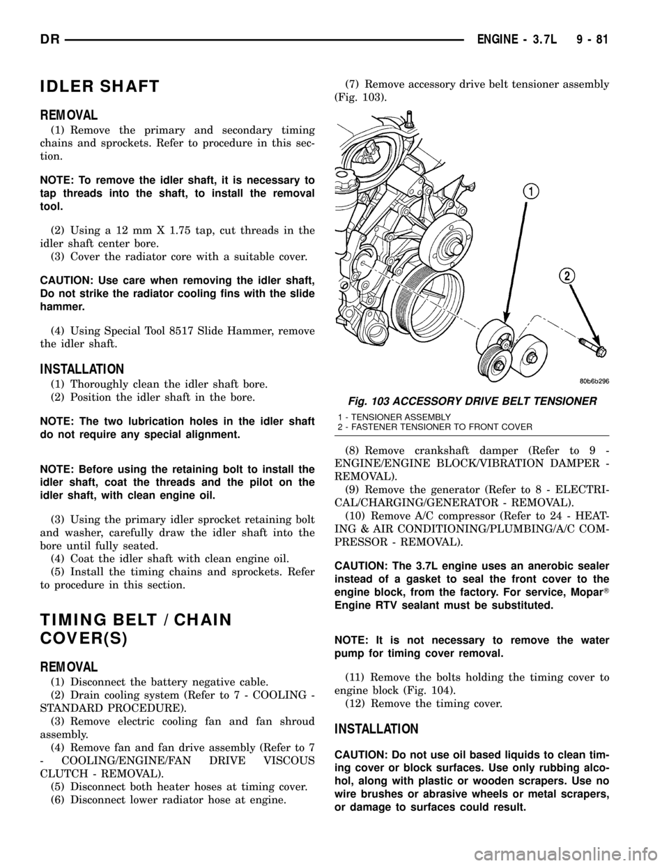
(6) Disconnect lower radiator hose at engine.(7) Remove accessory drive belt tensioner assembly
(Fig. 103).
(8) Remove crankshaft damper (Refer to 9 -
ENGINE/ENGINE BLOCK/VIBRATION DAMPER -
REMOVAL).
(9) Remove the generator (Refer to 8 - ELECTRI-
CAL/CHARGING/GENERATOR - REMOVAL).
(10) Remove A/C compressor (Refer to 24 - HEAT-
ING & AIR CONDITIONING/PLUMBING/A/C COM-
PRESSOR - REMOVAL).
CAUTION: The 3.7L engine uses an anerobic sealer
instead of a gasket to seal the front cover to the
engine block, from the factory. For service, MoparT
Engine RTV sealant must be substituted.
NOTE: It is not necessary to remove the water
pump for timing cover removal.
(11) Remove the bolts holding the timing cover to
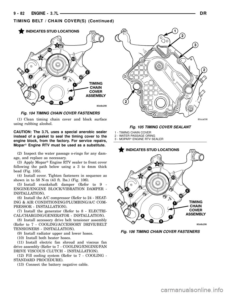
engine block (Fig. 104).
(12) Remove the timing cover.
INSTALLATION
CAUTION: Do not use oil based liquids to clean tim-
ing cover or block surfaces. Use only rubbing alco-
hol, along with plastic or wooden scrapers. Use no
wire brushes or abrasive wheels or metal scrapers,
or damage to surfaces could result.
Fig. 103 ACCESSORY DRIVE BELT TENSIONER
1 - TENSIONER ASSEMBLY
2 - FASTENER TENSIONER TO FRONT COVER
DRENGINE - 3.7L 9 - 81
Page 1305 of 2627

(1) Clean timing chain cover and block surface
using rubbing alcohol.
CAUTION: The 3.7L uses a special anerobic sealer
instead of a gasket to seal the timing cover to the
engine block, from the factory. For service repairs,
MoparTEngine RTV must be used as a substitute.
(2) Inspect the water passage o-rings for any dam-
age, and replace as necessary.
(3) Apply MopartEngine RTV sealer to front cover
following the path below usinga3to4mmthick
bead (Fig. 105).
(4) Install cover. Tighten fasteners in sequence as
shown in to 58 N´m (43 ft. lbs.) (Fig. 106).
(5) Install crankshaft damper (Refer to 9 -
ENGINE/ENGINE BLOCK/VIBRATION DAMPER -
INSTALLATION).
(6) Install the A/C compressor (Refer to 24 - HEAT-
ING & AIR CONDITIONING/PLUMBING/A/C COM-
PRESSOR - INSTALLATION).
(7) Install the generator (Refer to 8 - ELECTRI-
CAL/CHARGING/GENERATOR - INSTALLATION).
(8) Install accessory drive belt tensioner assembly
(Refer to 7 - COOLING/ACCESSORY DRIVE/BELT
TENSIONERS - INSTALLATION).
(9) Install radiator upper and lower hoses.
(10) Install both heater hoses.
(11) Install electric fan shroud and viscous fan
drive assembly (Refer to 7 - COOLING/ENGINE/FAN
DRIVE VISCOUS CLUTCH - INSTALLATION).
(12) Fill cooling system (Refer to 7 - COOLING -
STANDARD PROCEDURE).
(13) Connect the battery negative cable.
Fig. 104 TIMING CHAIN COVER FASTENERS
Fig. 105 TIMING COVER SEALANT
1 - TIMING CHAIN COVER
2 - WATER PASSAGE ORING
3 - MOPARTENGINE RTV SEALER
Fig. 106 TIMING CHAIN COVER FASTENERS
9 - 82 ENGINE - 3.7LDR
TIMING BELT / CHAIN COVER(S) (Continued)
Page 1319 of 2627

(19) Disconnect throttle and speed control cables.
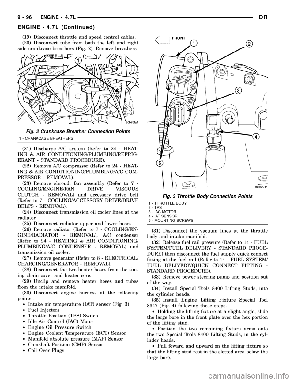
(20) Disconnect tube from both the left and right
side crankcase breathers (Fig. 2). Remove breathers
(21) Discharge A/C system (Refer to 24 - HEAT-
ING & AIR CONDITIONING/PLUMBING/REFRIG-
ERANT - STANDARD PROCEDURE).
(22) Remove A/C compressor (Refer to 24 - HEAT-
ING & AIR CONDITIONING/PLUMBING/A/C COM-
PRESSOR - REMOVAL).
(23) Remove shroud, fan assembly (Refer to 7 -
COOLING/ENGINE/FAN DRIVE VISCOUS
CLUTCH - REMOVAL) and accessory drive belt
(Refer to 7 - COOLING/ACCESSORY DRIVE/DRIVE
BELTS - REMOVAL).
(24) Disconnect transmission oil cooler lines at the
radiator.
(25) Disconnect radiator upper and lower hoses.
(26) Remove radiator (Refer to 7 - COOLING/EN-
GINE/RADIATOR - REMOVAL), A/C condenser
(Refer to 24 - HEATING & AIR CONDITIONING/
PLUMBING/A/C CONDENSER - REMOVAL) and
transmission oil cooler.
(27) Remove generator (Refer to 8 - ELECTRICAL/
CHARGING/GENERATOR - REMOVAL).
(28) Disconnect the two heater hoses from the tim-
ing chain cover and heater core.
(29) Unclip and remove heater hoses and tubes
from the intake manifold.
(30) Disconnect engine harness at the following
points :
²Intake air temperature (IAT) sensor (Fig. 3)
²Fuel Injectors
²Throttle Position (TPS) Switch
²Idle Air Control (IAC) Motor
²Engine Oil Pressure Switch
²Engine Coolant Temperature (ECT) Sensor
²Manifold absolute pressure (MAP) Sensor
²Camshaft Position (CMP) Sensor
²Coil Over Plugs(31) Disconnect the vacuum lines at the throttle
body and intake manifold.
(32) Release fuel rail pressure (Refer to 14 - FUEL
SYSTEM/FUEL DELIVERY - STANDARD PROCE-
DURE) then disconnect the fuel supply quick connect
fitting at the fuel rail (Refer to 14 - FUEL SYSTEM/
FUEL DELIVERY/QUICK CONNECT FITTING -
STANDARD PROCEDURE).
(33) Remove power steering pump and position out
of the way.
(34) Install Special Tools 8400 Lifting Studs, into
the cylinder heads.
(35) Install Engine Lifting Fixture Special Tool
8347 (Fig. 4) following these steps.
²Holding the lifting fixture at a slight angle, slide
the large bore in the front plate over the hex portion
of the lifting stud.
²Position the two remaining fixture arms onto
the two Special Tools 8400 Lifting Studs, in the cyl-
inder heads.
²Pull foward and upward on the lifting fixture so
that the lifting stud rest in the slotted area below the
large bore.
Fig. 2 Crankcase Breather Connection Points
1 - CRANKCASE BREATHERS
Fig. 3 Throttle Body Connection Points
1 - THROTTLE BODY
2 - TPS
3 - IAC MOTOR
4 - IAT SENSOR
5 - MOUNTING SCREWS
9 - 96 ENGINE - 4.7LDR
ENGINE - 4.7L (Continued)
Page 1321 of 2627

Position both the left and right side engine mount
brackets and install the through bolts and nuts.
Tighten nuts to4X2 vehicles95 N´m (70 ft. lbs.).
4X4 vehicles102 N´m (75 ft. lbs.).
(2)4X4 vehiclesInstall locknuts onto the engine
mount brackets. Tighten locknuts to 41 N´m (30 ft.
lbs.).
(3) Remove jack from under the transmission.
(4) Remove Engine Lifting Fixture Special Tool
8347 (Fig. 4).
(5) Remove Special Tools 8400 Lifting Studs.
(6) Position generator wiring behind the oil dip-
stick tube, then install the oil dipstick tube upper
mounting bolt.
(7) Connect both left and right side body ground
straps.
(8) Install power steering pump.
(9) Connect fuel supply line quick connect fitting
(Refer to 14 - FUEL SYSTEM/FUEL DELIVERY/
QUICK CONNECT FITTING - STANDARD PROCE-
DURE).
(10) Connect the vacuum lines at the throttle body
and intake manifold.
(11) Connect engine harness at the following
points (Fig. 3):
²Intake Air Temperature (IAT) Sensor
²Idle Air Control (IAC) Motor
²Fuel Injectors
²Throttle Position (TPS) Switch
²Engine Oil Pressure Switch
²Engine Coolant Temperature (ECT) Sensor
²Manifold Absolute Pressure (MAP) Sensor
²Camshaft Position (CMP) Sensor
²Coil Over Plugs
(12) Position and install heater hoses and tubes
onto intake manifold.
(13) Install the heater hoses onto the heater core
and the engine front cover.
(14) Install generator (Refer to 8 - ELECTRICAL/
CHARGING/GENERATOR - INSTALLATION).
(15) Install A/C condenser (Refer to 24 - HEATING
& AIR CONDITIONING/PLUMBING/A/C CON-
DENSER - INSTALLATION), radiator (Refer to 7 -
COOLING/ENGINE/RADIATOR - INSTALLATION)
and transmission oil cooler.
(16) Connect radiator upper and lower hoses.
(17) Connect the transmission oil cooler lines to
the radiator.
(18) Install accessory drive belt (Refer to 7 -
COOLING/ACCESSORY DRIVE/DRIVE BELTS -INSTALLATION), fan assembly and shroud (Refer to
7 - COOLING/ENGINE/FAN DRIVE VISCOUS
CLUTCH - INSTALLATION).
(19) Install A/C compressor (Refer to 24 - HEAT-
ING & AIR CONDITIONING/PLUMBING/A/C COM-
PRESSOR - INSTALLATION).
(20) Install both breathers. Connect tube to both
crankcase breathers (Fig. 2).
(21) Connect throttle and speed control cables.
(22) Install throttle body resonator assembly and
air inlet hose. Tighten clamps 4 N´m (35 in. lbs.).
(23) Raise vehicle.
(24) Install transmission to engine mounting bolts.
Tighten the bolts to 41 N´m (30 ft. lbs.).
(25) Install torque converter bolts (Automatic
Transmission Only).
(26) Connect crankshaft position sensor (Fig. 1).
(27)4X4 vehiclesPosition and install the axle
isolator bracket onto the axle, transmission and
engine block. Tighten bolts to specification (Refer to 9
- ENGINE - SPECIFICATIONS).
(28) Install starter (Refer to 8 - ELECTRICAL/
STARTING/STARTER MOTOR - INSTALLATION).
CAUTION: The structural cover requires a specific
torque sequence. Failure to follow this sequence
may cause severe damage to the cover.
(29) Install structural cover (Refer to 9 - ENGINE/
ENGINE BLOCK/STRUCTURAL COVER - INSTAL-
LATION).
(30) Install exhaust crossover pipe.
(31) Install engine block heater power cable, If
equipped.
(32)4X4 vehiclesConnect axle vent tube to left
side engine mount.
(33) Lower vehicle.
(34) Check and fill engine oil.
(35) Recharge the A/C system (Refer to 24 - HEAT-
ING & AIR CONDITIONING/PLUMBING/REFRIG-
ERANT - STANDARD PROCEDURE).
(36) Refill the engine cooling system (Refer to 7 -
COOLING - STANDARD PROCEDURE).
(37) Install the battery tray and battery.
(38) Connect the battery positive and negative
cables.
(39) Start the engine and check for leaks.
9 - 98 ENGINE - 4.7LDR
ENGINE - 4.7L (Continued)
Page 1414 of 2627

(6) Remove the viscous fan/drive (Refer to 7 -
COOLING/ENGINE/RADIATOR FAN - REMOVAL).
(7) Remove radiator (Refer to 7 - COOLING/EN-
GINE/RADIATOR - REMOVAL).
(8) Remove the upper crossmember and top core
support.
NOTE: It is not necessary to drain A/C system for
engine removal.
(9) Remove the A/C compressor with the lines
attached. Secure compressor out of the way.
(10) Remove generator assembly (Refer to 8 -
ELECTRICAL/CHARGING/GENERATOR -
REMOVAL).
(11) Remove the intake manifold and IAFM as an
assembly(Refer to 9 - ENGINE/MANIFOLDS/IN-
TAKE MANIFOLD - REMOVAL).
(12) Disconnect the heater hoses.
NOTE: It is not necessary to disconnect P/S hoses
from pump, for P/S pump removal.
(13) Remove the power steering pump and set
aside.
(14) Disconnect the fuel supply line (Refer to 14 -
FUEL SYSTEM/FUEL DELIVERY/QUICK CON-
NECT FITTING - STANDARD PROCEDURE).
(15) Raise and support the vehicle on a hoist and
drain the engine oil.
(16) Remove engine front mount thru-bolt nuts.
(17) Remove right side axle retaining bolts.
(18) Disconnect the transmission oil cooler lines
from their retainers at the oil pan bolts.
(19) Disconnect exhaust pipe at manifolds.
(20) Disconnect the starter wires. Remove starter
motor (Refer to 8 - ELECTRICAL/STARTING/
STARTER MOTOR - REMOVAL).
(21) Remove the structural dust cover and trans-
mission inspection cover,(Refer to 9 - ENGINE/EN-
GINE BLOCK/STRUCTURAL COVER - REMOVAL).
(22) Remove drive plate to converter bolts (Auto-
matic transmission equipped vehicles).
(23) Remove transmission bell housing to engine
block bolts.
(24) Lower the vehicle.
(25) Install engine lift fixture, special tool # 8984.
(26) Separate engine from transmission, remove
engine from vehicle, and install engine assembly on a
repair stand.
INSTALLATION
(1) Install engine lift fixture Special tool # 8984.
(2) Position the engine in the engine compartment.
(3) Lower engine into compartment and align
engine with transmission:²Manual Transmission: Align clutch disc assem-
bly (if disturbed). Install transmission input shaft
into clutch disc while mating engine and transmis-
sion surfaces. Install two transmission to engine
block mounting bolts finger tight.
²Automatic Transmission: Mate engine and trans-
mission and install two transmission to engine block
mounting bolts finger tight.
(4) Position the thru-bolt into the support cushion
brackets.
(5) Lower engine assembly until engine mount
through bolts rest in mount perches.
(6) Install remaining transmission to engine block
mounting bolts and tighten.
(7) Tighten engine mount through bolts.
(8) Install drive plate to torque converter bolts.
(Automatic transmission models)
(9) Install the structural dust cover and transmis-
sion dust cover,(Refer to 9 - ENGINE/ENGINE
BLOCK/STRUCTURAL COVER - INSTALLATION).
(10) Install the starter and connect the starter
wires (Refer to 8 - ELECTRICAL/STARTING/
STARTER MOTOR - INSTALLATION).
(11) Install exhaust pipe to manifold.
(12) Lower the vehicle.
(13) Remove engine lift fixture, special tool # 8984.
(14) Connect the fuel supply line (Refer to 14 -
FUEL SYSTEM/FUEL DELIVERY/QUICK CON-
NECT FITTING - STANDARD PROCEDURE).
(15) Reinstall the power steering pump.
(16) Connect the heater hoses.
(17) Install the intake manifold.
(18) Using a new gasket, install throttle body
(Refer to 14 - FUEL SYSTEM/FUEL INJECTION/
THROTTLE BODY - INSTALLATION).
(19) Install the generator and wire connections
(Refer to 8 - ELECTRICAL/CHARGING/GENERA-
TOR - INSTALLATION).
(20) Install a/c compressor and lines (Refer to 24 -
HEATING & AIR CONDITIONING/PLUMBING/A/C
COMPRESSOR - INSTALLATION).
(21) Install the accessory drive belt (Refer to 7 -
COOLING/ACCESSORY DRIVE/DRIVE BELTS -
INSTALLATION).
(22) Install upper radiator support crossmember.
(23) Install radiator (Refer to 7 - COOLING/EN-
GINE/RADIATOR - INSTALLATION).
(24) Connect the radiator lower hose.
(25) Connect the transmission oil cooler lines to
the radiator.
(26) Install the fan shroud.
(27) Install the fan (Refer to 7 - COOLING/EN-
GINE/RADIATOR FAN - INSTALLATION).
(28) Connect the radiator upper hose.
(29) Install the washer bottle.
(30) Connect the transmission cooler lines.
DRENGINE - 5.7L 9 - 191
ENGINE - 5.7L (Continued)