1998 DODGE RAM 1500 torque
[x] Cancel search: torquePage 1694 of 2627

PUMP
TABLE OF CONTENTS
page page
PUMP
DESCRIPTION.........................39
OPERATION...........................40
DIAGNOSIS AND TESTING - PUMP LEAKAGE . 40
STANDARD PROCEDURE
STANDARD PROCEDURE - POWER
STEERING PUMP - INITIAL OPERATION....40
STANDARD PROCEDURE - FLUSHING
POWER STEERING SYSTEM............40
REMOVAL
REMOVAL - GAS......................41
REMOVAL - DIESEL...................41
INSTALLATION
INSTALLATION - GAS..................42
INSTALLATION - DIESEL................42
SPECIFICATIONS
TORQUE CHART......................42
FLUID
DESCRIPTION.........................43
STANDARD PROCEDURE - POWER
STEERING FLUID LEVEL CHECKING......43
FLUID COOLER
REMOVAL.............................43
INSTALLATION.........................43
HOSES - I.F.S.
REMOVAL
REMOVAL - RETURN HOSE - GEAR TO
COOLER............................44
REMOVAL - PRESSURE HOSE...........44
REMOVAL - RETURN HOSE - RESERVOIR
TO COOLER.........................44INSTALLATION
INSTALLATION - RETURN HOSE - GEAR TO
COOLER............................44
INSTALLATION - PRESSURE HOSE.......44
INSTALLATION - RETURN HOSE -
RESERVOIR TO COOLER...............44
HOSES - LINK/COIL
REMOVAL
REMOVAL - RETURN HOSE - GEAR TO
COOLER............................45
REMOVAL - PRESSURE HOSE...........45
REMOVAL - RETURN HOSE - RESERVOIR
TO COOLER.........................45
INSTALLATION
INSTALLATION - RETURN HOSE - GEAR TO
COOLER............................45
INSTALLATION - PRESSURE HOSE.......45
INSTALLATION - RETURN HOSE -
RESERVOIR TO COOLER...............45
POWER STEERING PRESSURE SWITCH
DESCRIPTION.........................46
OPERATION...........................46
REMOVAL - 3.7L & 5.7L..................46
INSTALLATION - 3.7L & 5.7L...............46
PULLEY
REMOVAL.............................47
INSTALLATION.........................47
RESERVOIR
REMOVAL.............................47
INSTALLATION.........................47
PUMP
DESCRIPTION
CAUTION: MOPARTATF+4 is to be used in the
power steering system. No other power steering or
automatic transmission fluid is to be used in the
system. Damage may result to the power steering
pump and system if any other fluid is used, and do
not overfill.The pump is connected to the steering gear via the
pressure hose and the return hose. The pump shaft
has a pressed-on pulley that is belt driven by the
crankshaft pulley.
All vehicles are equipped with a power steering
fluid cooler.
NOTE: Power steering pumps are not interchange-
able with pumps installed on other vehicles.
DRPUMP 19 - 39
Page 1697 of 2627

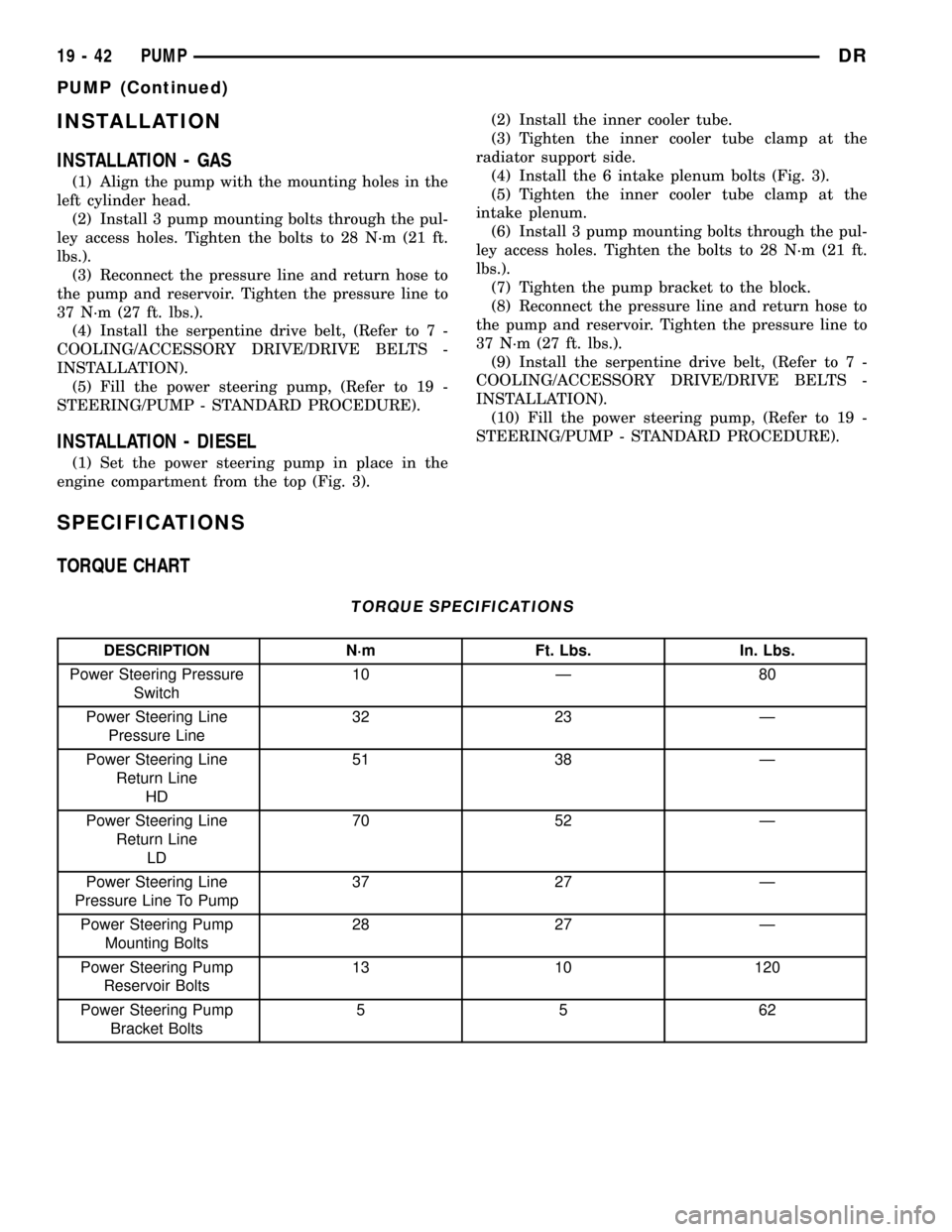
INSTALLATION
INSTALLATION - GAS
(1) Align the pump with the mounting holes in the
left cylinder head.
(2) Install 3 pump mounting bolts through the pul-
ley access holes. Tighten the bolts to 28 N´m (21 ft.
lbs.).
(3) Reconnect the pressure line and return hose to
the pump and reservoir. Tighten the pressure line to
37 N´m (27 ft. lbs.).
(4) Install the serpentine drive belt, (Refer to 7 -
COOLING/ACCESSORY DRIVE/DRIVE BELTS -
INSTALLATION).
(5) Fill the power steering pump, (Refer to 19 -
STEERING/PUMP - STANDARD PROCEDURE).
INSTALLATION - DIESEL
(1) Set the power steering pump in place in the
engine compartment from the top (Fig. 3).(2) Install the inner cooler tube.
(3) Tighten the inner cooler tube clamp at the
radiator support side.
(4) Install the 6 intake plenum bolts (Fig. 3).
(5) Tighten the inner cooler tube clamp at the
intake plenum.
(6) Install 3 pump mounting bolts through the pul-
ley access holes. Tighten the bolts to 28 N´m (21 ft.
lbs.).
(7) Tighten the pump bracket to the block.
(8) Reconnect the pressure line and return hose to
the pump and reservoir. Tighten the pressure line to
37 N´m (27 ft. lbs.).
(9) Install the serpentine drive belt, (Refer to 7 -
COOLING/ACCESSORY DRIVE/DRIVE BELTS -
INSTALLATION).
(10) Fill the power steering pump, (Refer to 19 -
STEERING/PUMP - STANDARD PROCEDURE).
SPECIFICATIONS
TORQUE CHART
TORQUE SPECIFICATIONS
DESCRIPTION N´m Ft. Lbs. In. Lbs.
Power Steering Pressure
Switch10 Ð 80
Power Steering Line
Pressure Line32 23 Ð
Power Steering Line
Return Line
HD51 38 Ð
Power Steering Line
Return Line
LD70 52 Ð
Power Steering Line
Pressure Line To Pump37 27 Ð
Power Steering Pump
Mounting Bolts28 27 Ð
Power Steering Pump
Reservoir Bolts13 10 120
Power Steering Pump
Bracket Bolts5562
19 - 42 PUMPDR
PUMP (Continued)
Page 1701 of 2627

(4) Remove the support and lower the vehicle.
(5) Reconnect the return hose at the reservoir.
(6) Refill the power steering system,(Refer to 19 -
STEERING/PUMP - STANDARD PROCEDURE).
POWER STEERING PRESSURE
SWITCH
DESCRIPTION
A pressure sensing switch is used in the power
steering system. It is mounted on the high-pressure
steering hose (Fig. 9). This switch will be used with
both 3.7L and 5.7L engines. There is no pressure
switch used for the 4.7L or the 5.9L pump.
OPERATION
The switch is used on the 3.7L V-6 & 5.7L V-8
engines.
The power steering pressure switch provides an
input to the Powertrain Control Module (PCM). This
input is provided during periods of high steering
pump load and low engine rpm; such as during park-
ing maneuvers. The PCM increases the idle speed
through the Idle Air Control (IAC) motor. This is
done to prevent the engine from stalling under the
increased load.
When steering pump pressure exceeds 3275 kPa
690 kPa (475 psi 100 psi), the Normally Closed
(NC) switch will open and the PCM will increase the
engine idle speed. This will prevent the engine from
stalling.
When pump pressure drops to approximately 1379
kPa (200 psi), the switch circuit will re-close and
engine idle speed will return to its previous setting.
REMOVAL - 3.7L & 5.7L
The power steering pressure switch is installed in
the power steering high-pressure hose (Fig. 9).
(1) Disconnect electrical connector from power
steering pressure switch.(2) Place a small container or shop towel beneath
switch to collect any excess fluid.
(3) Remove switch. Use back-up wrench on power
steering line to prevent line bending.
INSTALLATION - 3.7L & 5.7L
This switch is used only with the 3.7L V±6 and the
5.7L V-8 engines.
(1) Install power steering switch into power steer-
ing line.
(2) Tighten to 8±11 N´m (70±100 in. lbs.) torque.
(3) Connect electrical connector to switch.
(4) Check power steering fluid and add as neces-
sary.
(5) Start engine and again check power steering
fluid. Add fluid if necessary.
Fig. 9 PRESSURE SWITCH
1 - POWER STEERING PULLEY
2 - POWER STEERING PUMP HOUSING
3 - POWER STEERING FLUID RESERVOIR
4 - RETURN HOSE
5 - HIGH PRESSURE HOSE WITH PRESSURE SWITCH
19 - 46 PUMPDR
HOSES - LINK/COIL (Continued)
Page 1743 of 2627

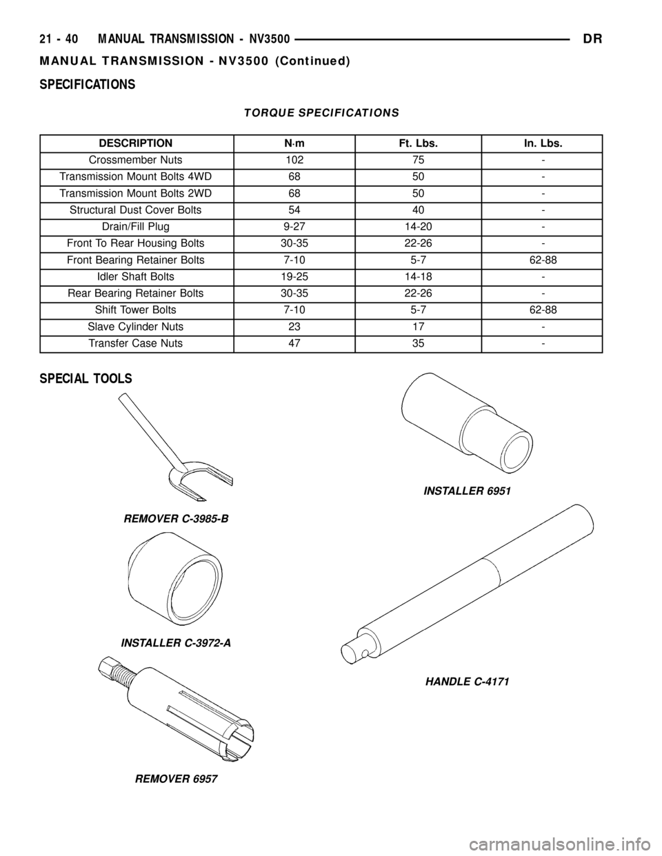
SPECIFICATIONS
TORQUE SPECIFICATIONS
DESCRIPTION N´m Ft. Lbs. In. Lbs.
Crossmember Nuts 102 75 -
Transmission Mount Bolts 4WD 68 50 -
Transmission Mount Bolts 2WD 68 50 -
Structural Dust Cover Bolts 54 40 -
Drain/Fill Plug 9-27 14-20 -
Front To Rear Housing Bolts 30-35 22-26 -
Front Bearing Retainer Bolts 7-10 5-7 62-88
Idler Shaft Bolts 19-25 14-18 -
Rear Bearing Retainer Bolts 30-35 22-26 -
Shift Tower Bolts 7-10 5-7 62-88
Slave Cylinder Nuts 23 17 -
Transfer Case Nuts 47 35 -
SPECIAL TOOLS
REMOVER C-3985-B
INSTALLER C-3972-A
REMOVER 6957
INSTALLER 6951
HANDLE C-4171
21 - 40 MANUAL TRANSMISSION - NV3500DR
MANUAL TRANSMISSION - NV3500 (Continued)
Page 1782 of 2627

(10) Tighten fifth gear nut with Nut Wrench 6743
and high capacity torque wrench. Tighten nut to 366-
380 N´m (270-280 ft. lbs.). Have helper hold trans-
mission steady if necessary.
(11) Torque the fifth gear clamp nut clamping bolt
to 13.5 N´m (10 ft. lbs.).
(12) Unlock the mainshaft gears by shifting all
synchro sleeves out of the engaged position.
EXTENSION/ADAPTER HOUSING
(1) Clean mating surfaces of extension/adapter
housing and gear case with a wax and grease
remover.
(2) Check alignment dowels in gear case and hous-
ing or adapter. Be sure dowels are in position and
seated.
(3) Apply Mopar Silicone Sealer or equivalent to
gear case and housing mating surfaces.
(4) Align and install extension/adapter housing on
gear case (Fig. 128).
(5) Apply Mopar Lock N' Seal or equivalent to
threads of extension/adapter housing bolts.
(6) Install and tighten housing bolts to 54 N´m (40
ft. lbs.).SHIFT MECHANISM
(1) Clean mating surfaces of shift cover and gear
case with wax and grease remover.
(2) Apply a small amount of Mopar silicone sealer
or equivalent to sealing surface of shift cover.
CAUTION: Do not over-apply an excesive amount
sealer. Excess can squeezed into gear case and
could block lubricant feed holes in time.
(3) Lubricate synchro sleeves with CastroltSyn-
torq gear lubricant or equivalent. Then apply light
coat of petroleum jelly to shift fork contact surfaces.
(4) Verify shift fork pads (Fig. 129) are secure.
(5) Verify 1-2 and 3-4 synchro sleeves and forks in
shift cover are in neutral position.
(6) Align and seat shift cover on transmission.
NOTE: If cover will not seat, it may not be aligned
on gear case dowels or shift forks are not aligned
with sleeves and shift lug.
(7) Apply Mopar Lock N' Seal or equivalent to
threads of shift cover bolts.
(8) Install shift cover bolts and tighten to 27-31
N´m (216-276 in. lbs.).
(9) Apply sealer to backup lamp switch. Install
switch into cover and tighten to 22-34 N´m (193-265
in. lbs.).
(10) Install vent assembly if removed. Apply an
adhesive/sealer to vent tube to help secure it in cover.
Fig. 128 INSTALLING EXTENSION/ADAPTER
HOUSING
1 - GEAR CASE
2 - EXTENSION HOUSING
Fig. 129 SHIFT FORK PAD
1 - SHIFT FORK PADS
2 - FIFTH-REVERSE FORK
DRMANUAL TRANSMISSION - NV4500 21 - 79
MANUAL TRANSMISSION - NV4500 (Continued)
Page 1784 of 2627

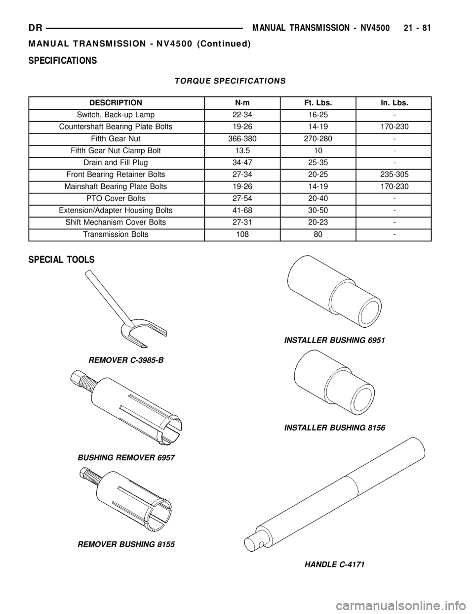
SPECIFICATIONS
TORQUE SPECIFICATIONS
DESCRIPTION N´m Ft. Lbs. In. Lbs.
Switch, Back-up Lamp 22-34 16-25 -
Countershaft Bearing Plate Bolts 19-26 14-19 170-230
Fifth Gear Nut 366-380 270-280 -
Fifth Gear Nut Clamp Bolt 13.5 10 -
Drain and Fill Plug 34-47 25-35 -
Front Bearing Retainer Bolts 27-34 20-25 235-305
Mainshaft Bearing Plate Bolts 19-26 14-19 170-230
PTO Cover Bolts 27-54 20-40 -
Extension/Adapter Housing Bolts 41-68 30-50 -
Shift Mechanism Cover Bolts 27-31 20-23 -
Transmission Bolts 108 80 -
SPECIAL TOOLS
REMOVER C-3985-B
BUSHING REMOVER 6957
REMOVER BUSHING 8155
INSTALLER BUSHING 6951
INSTALLER BUSHING 8156
HANDLE C-4171
DRMANUAL TRANSMISSION - NV4500 21 - 81
MANUAL TRANSMISSION - NV4500 (Continued)
Page 1826 of 2627

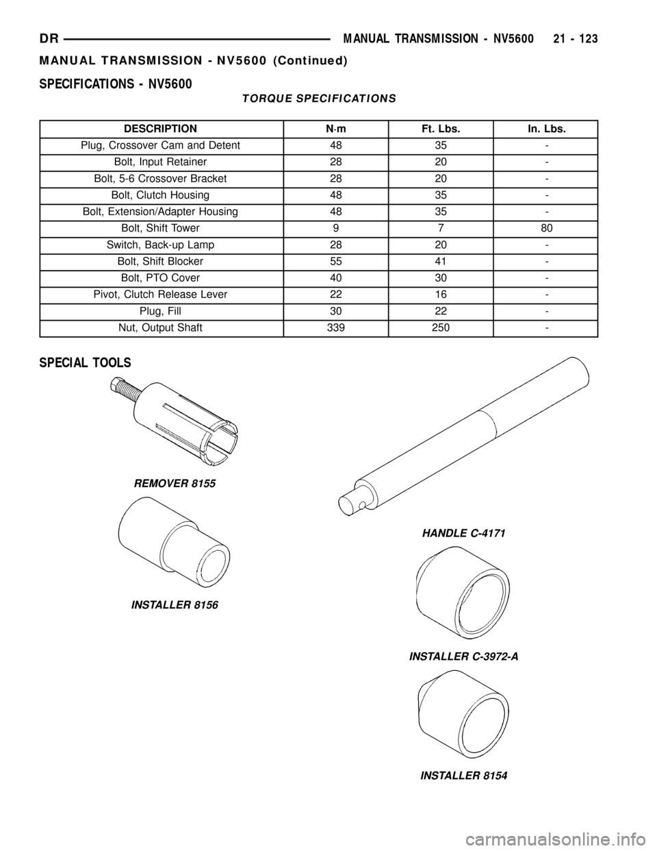
SPECIFICATIONS - NV5600
TORQUE SPECIFICATIONS
DESCRIPTION N´m Ft. Lbs. In. Lbs.
Plug, Crossover Cam and Detent 48 35 -
Bolt, Input Retainer 28 20 -
Bolt, 5-6 Crossover Bracket 28 20 -
Bolt, Clutch Housing 48 35 -
Bolt, Extension/Adapter Housing 48 35 -
Bolt, Shift Tower 9 7 80
Switch, Back-up Lamp 28 20 -
Bolt, Shift Blocker 55 41 -
Bolt, PTO Cover 40 30 -
Pivot, Clutch Release Lever 22 16 -
Plug, Fill 30 22 -
Nut, Output Shaft 339 250 -
SPECIAL TOOLS
REMOVER 8155
INSTALLER 8156
HANDLE C-4171
INSTALLER C-3972-A
INSTALLER 8154
DRMANUAL TRANSMISSION - NV5600 21 - 123
MANUAL TRANSMISSION - NV5600 (Continued)
Page 1834 of 2627

OUTPUT SHAFT FRONT BEARING
REMOVAL............................216
INSTALLATION........................216
OUTPUT SHAFT REAR BEARING
REMOVAL............................216
INSTALLATION........................217
OVERDRIVE CLUTCH
DESCRIPTION........................217
OPERATION..........................217
OVERDRIVE UNIT
REMOVAL............................218
DISASSEMBLY........................218
CLEANING...........................225
INSPECTION.........................225
ASSEMBLY...........................226
INSTALLATION........................235
OVERRUNNING CLUTCH CAM/OVERDRIVE
PISTON RETAINER
DESCRIPTION........................236
OPERATION..........................236
DISASSEMBLY........................236
CLEANING...........................236
INSPECTION.........................237
ASSEMBLY...........................237
PISTONS
DESCRIPTION........................239
OPERATION..........................239
PLANETARY GEARTRAIN/OUTPUT SHAFT
DESCRIPTION........................241
OPERATION..........................241
DISASSEMBLY........................242
INSPECTION.........................243
ASSEMBLY...........................244
REAR CLUTCH
DESCRIPTION........................247
OPERATION..........................248
DISASSEMBLY........................248
CLEANING...........................248
INSPECTION.........................248
ASSEMBLY...........................249
REAR SERVO
DESCRIPTION........................251
OPERATION..........................251
DISASSEMBLY........................251
CLEANING...........................251
ASSEMBLY...........................251
SHIFT MECHANISM
DESCRIPTION........................252OPERATION..........................252
SOLENOID
DESCRIPTION........................252
OPERATION..........................252
SPEED SENSOR
DESCRIPTION........................253
OPERATION..........................253
THROTTLE VALVE CABLE
DESCRIPTION........................253
ADJUSTMENTS - THROTTLE VALVE CABLE . 254
TORQUE CONVERTER
DESCRIPTION........................255
OPERATION..........................259
REMOVAL............................260
INSTALLATION........................260
TORQUE CONVERTER DRAINBACK VALVE
DESCRIPTION........................261
OPERATION..........................261
STANDARD PROCEDURE - TORQUE
CONVERTER DRAINBACK VALVE........261
TOW/HAUL OVERDRIVE SWITCH
DESCRIPTION........................261
OPERATION..........................262
DIAGNOSIS AND TESTING - OVERDRIVE
ELECTRICAL CONTROLS..............262
REMOVAL............................262
INSTALLATION........................262
TRANSMISSION RANGE SENSOR
DESCRIPTION........................263
OPERATION..........................263
DIAGNOSIS AND TESTING - TRANSMISSION
RANGE SENSOR (TRS)................264
REMOVAL............................265
INSTALLATION........................266
TRANSMISSION TEMPERATURE SENSOR
DESCRIPTION........................267
OPERATION..........................267
VALVE BODY
DESCRIPTION........................267
OPERATION..........................272
REMOVAL............................286
DISASSEMBLY........................287
CLEANING...........................298
INSPECTION.........................298
ASSEMBLY...........................299
INSTALLATION........................309
ADJUSTMENTS - VALVE BODY...........310
DRAUTOMATIC TRANSMISSION - 48RE 21 - 131