1998 DODGE RAM 1500 torque
[x] Cancel search: torquePage 1606 of 2627
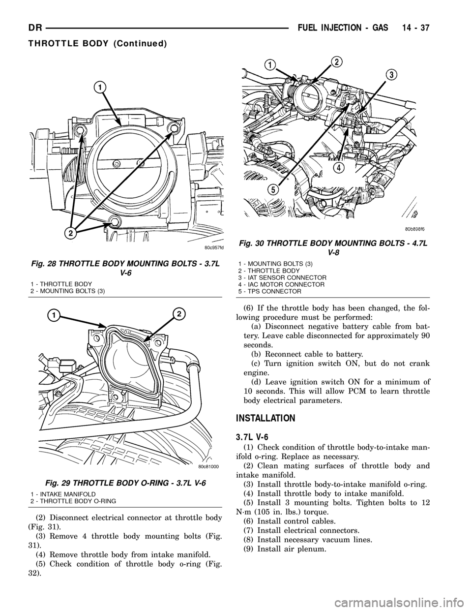
(2) Disconnect electrical connector at throttle body
(Fig. 31).
(3) Remove 4 throttle body mounting bolts (Fig.
31).
(4) Remove throttle body from intake manifold.
(5) Check condition of throttle body o-ring (Fig.
32).(6) If the throttle body has been changed, the fol-
lowing procedure must be performed:
(a) Disconnect negative battery cable from bat-
tery. Leave cable disconnected for approximately 90
seconds.
(b) Reconnect cable to battery.
(c) Turn ignition switch ON, but do not crank
engine.
(d) Leave ignition switch ON for a minimum of
10 seconds. This will allow PCM to learn throttle
body electrical parameters.
INSTALLATION
3.7L V-6
(1) Check condition of throttle body-to-intake man-
ifold o-ring. Replace as necessary.
(2) Clean mating surfaces of throttle body and
intake manifold.
(3) Install throttle body-to-intake manifold o-ring.
(4) Install throttle body to intake manifold.
(5) Install 3 mounting bolts. Tighten bolts to 12
N´m (105 in. lbs.) torque.
(6) Install control cables.
(7) Install electrical connectors.
(8) Install necessary vacuum lines.
(9) Install air plenum.
Fig. 28 THROTTLE BODY MOUNTING BOLTS - 3.7L
V-6
1 - THROTTLE BODY
2 - MOUNTING BOLTS (3)
Fig. 29 THROTTLE BODY O-RING - 3.7L V-6
1 - INTAKE MANIFOLD
2 - THROTTLE BODY O-RING
Fig. 30 THROTTLE BODY MOUNTING BOLTS - 4.7L
V-8
1 - MOUNTING BOLTS (3)
2 - THROTTLE BODY
3 - IAT SENSOR CONNECTOR
4 - IAC MOTOR CONNECTOR
5 - TPS CONNECTOR
DRFUEL INJECTION - GAS 14 - 37
THROTTLE BODY (Continued)
Page 1607 of 2627

4.7L V-8
(1) Clean throttle body-to-intake manifold o-ring.(2) Clean mating surfaces of throttle body and
intake manifold.
(3) Install throttle body to intake manifold by posi-
tioning throttle body to manifold alignment pins.
(4) Install three mounting bolts. Tighten bolts to
12 N´m (105 in. lbs.) torque.
(5) Install control cables.
(6) Install vacuum line to throttle body.
(7) Install electrical connectors.
(8) Install air plenum.
5.7L V-8
CAUTION: Do not use spray (carb) cleaners on any
part of the throttle body. Do not apply silicone lubri-
cants to any part of the throttle body.
(1) Clean and check condition of throttle body-to-
intake manifold o-ring.
(2) Clean mating surfaces of throttle body and
intake manifold.
(3) Install throttle body to intake manifold by posi-
tioning throttle body to manifold alignment pins.
(4) Install 4 mounting bolts. Refer to Torque Spec-
ifications.
(5) Install electrical connector.
(6) Install air plenum.
(7)If the throttle body has been changed, the
following procedure must be performed:
(a) Disconnect negative battery cable from bat-
tery. Leave cable disconnected for approximately 90
seconds.
(b) Reconnect cable to battery.
(c) Turn ignition switch ON, but do not crank
engine.
(d) Leave ignition switch ON for a minimum of
10 seconds. This will allow PCM to learn throttle
body electrical parameters.
THROTTLE CONTROL CABLE
REMOVAL
3.7L V-6
CAUTION: Be careful not to damage or kink cable
core wire (within cable sheathing) while servicing
accelerator pedal or throttle cable.
(1) From inside vehicle, hold up accelerator pedal.
Remove plastic cable retainer (clip) and throttle cable
core wire from upper end of pedal arm (Fig. 1). Plas-
tic cable retainer snaps into top of pedal arm.
(2) Remove cable core wire at pedal arm.
(3) From inside vehicle, remove metal clip holding
cable to dashpanel (Fig. 1).
Fig. 31 5.7L V-8 THROTTLE BODY
1 - THROTTLE BODY
2 - ELECTRICAL CONNECTOR
3 - SILICONE SEAL
4 - MOUNTING BOLTS (4)
Fig. 32 5.7L V-8 THROTTLE BODY O-RING
1 - INTAKE MANIFOLD
2 - THROTTLE BODY O-RING
14 - 38 FUEL INJECTION - GASDR
THROTTLE BODY (Continued)
Page 1612 of 2627
INSTALLATION
3.7L V-6
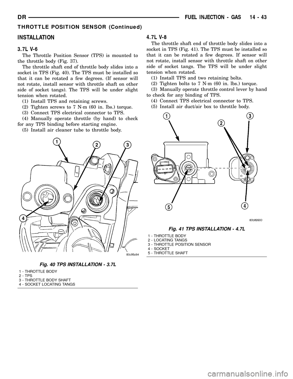
The Throttle Position Sensor (TPS) is mounted to
the throttle body (Fig. 37).
The throttle shaft end of throttle body slides into a
socket in TPS (Fig. 40). The TPS must be installed so
that it can be rotated a few degrees. (If sensor will
not rotate, install sensor with throttle shaft on other
side of socket tangs). The TPS will be under slight
tension when rotated.
(1) Install TPS and retaining screws.
(2) Tighten screws to 7 N´m (60 in. lbs.) torque.
(3) Connect TPS electrical connector to TPS.
(4) Manually operate throttle (by hand) to check
for any TPS binding before starting engine.
(5) Install air cleaner tube to throttle body.
4.7L V-8
The throttle shaft end of throttle body slides into a
socket in TPS (Fig. 41). The TPS must be installed so
that it can be rotated a few degrees. If sensor will
not rotate, install sensor with throttle shaft on other
side of socket tangs. The TPS will be under slight
tension when rotated.
(1) Install TPS and two retaining bolts.
(2) Tighten bolts to 7 N´m (60 in. lbs.) torque.
(3) Manually operate throttle control lever by hand
to check for any binding of TPS.
(4) Connect TPS electrical connector to TPS.
(5) Install air duct/air box to throttle body.
Fig. 40 TPS INSTALLATION - 3.7L
1 - THROTTLE BODY
2 - TPS
3 - THROTTLE BODY SHAFT
4 - SOCKET LOCATING TANGS
Fig. 41 TPS INSTALLATION - 4.7L
1 - THROTTLE BODY
2 - LOCATING TANGS
3 - THROTTLE POSITION SENSOR
4 - SOCKET
5 - THROTTLE SHAFT
DRFUEL INJECTION - GAS 14 - 43
THROTTLE POSITION SENSOR (Continued)
Page 1613 of 2627
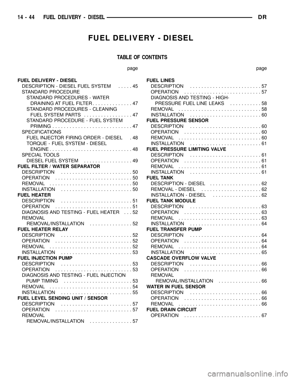
FUEL DELIVERY - DIESEL
TABLE OF CONTENTS
page page
FUEL DELIVERY - DIESEL
DESCRIPTION - DIESEL FUEL SYSTEM.....45
STANDARD PROCEDURE
STANDARD PROCEDURES - WATER
DRAINING AT FUEL FILTER..............47
STANDARD PROCEDURES - CLEANING
FUEL SYSTEM PARTS.................47
STANDARD PROCEDURE - FUEL SYSTEM
PRIMING............................47
SPECIFICATIONS
FUEL INJECTOR FIRING ORDER - DIESEL . 48
TORQUE - FUEL SYSTEM - DIESEL
ENGINE.............................48
SPECIAL TOOLS
DIESEL FUEL SYSTEM.................49
FUEL FILTER / WATER SEPARATOR
DESCRIPTION.........................50
OPERATION...........................50
REMOVAL.............................50
INSTALLATION.........................50
FUEL HEATER
DESCRIPTION.........................51
OPERATION...........................51
DIAGNOSIS AND TESTING - FUEL HEATER . . . 52
REMOVAL
REMOVAL/INSTALLATION...............52
FUEL HEATER RELAY
DESCRIPTION.........................52
OPERATION...........................52
REMOVAL.............................52
INSTALLATION.........................53
FUEL INJECTION PUMP
DESCRIPTION.........................53
OPERATION...........................53
DIAGNOSIS AND TESTING - FUEL INJECTION
PUMP TIMING........................53
REMOVAL.............................54
INSTALLATION.........................55
FUEL LEVEL SENDING UNIT / SENSOR
DESCRIPTION.........................57
OPERATION...........................57
REMOVAL
REMOVAL/INSTALLATION...............57FUEL LINES
DESCRIPTION.........................57
OPERATION...........................57
DIAGNOSIS AND TESTING - HIGH-
PRESSURE FUEL LINE LEAKS...........58
REMOVAL.............................58
INSTALLATION.........................60
FUEL PRESSURE SENSOR
DESCRIPTION.........................60
OPERATION...........................60
REMOVAL.............................60
INSTALLATION.........................61
FUEL PRESSURE LIMITING VALVE
DESCRIPTION.........................61
OPERATION...........................61
REMOVAL.............................61
INSTALLATION.........................61
FUEL TANK
DESCRIPTION - DIESEL..................62
REMOVAL - DIESEL.....................62
INSTALLATION - DIESEL.................62
FUEL TANK MODULE
DESCRIPTION.........................63
OPERATION...........................63
REMOVAL.............................63
INSTALLATION.........................64
FUEL TRANSFER PUMP
DESCRIPTION.........................64
OPERATION...........................64
REMOVAL.............................64
INSTALLATION.........................65
CASCADE OVERFLOW VALVE
DESCRIPTION.........................66
OPERATION...........................66
REMOVAL
REMOVAL/INSTALLATION...............66
WATER IN FUEL SENSOR
DESCRIPTION.........................66
OPERATION...........................66
REMOVAL.............................66
FUEL DRAIN CIRCUIT
OPERATION...........................67
14 - 44 FUEL DELIVERY - DIESELDR
Page 1617 of 2627
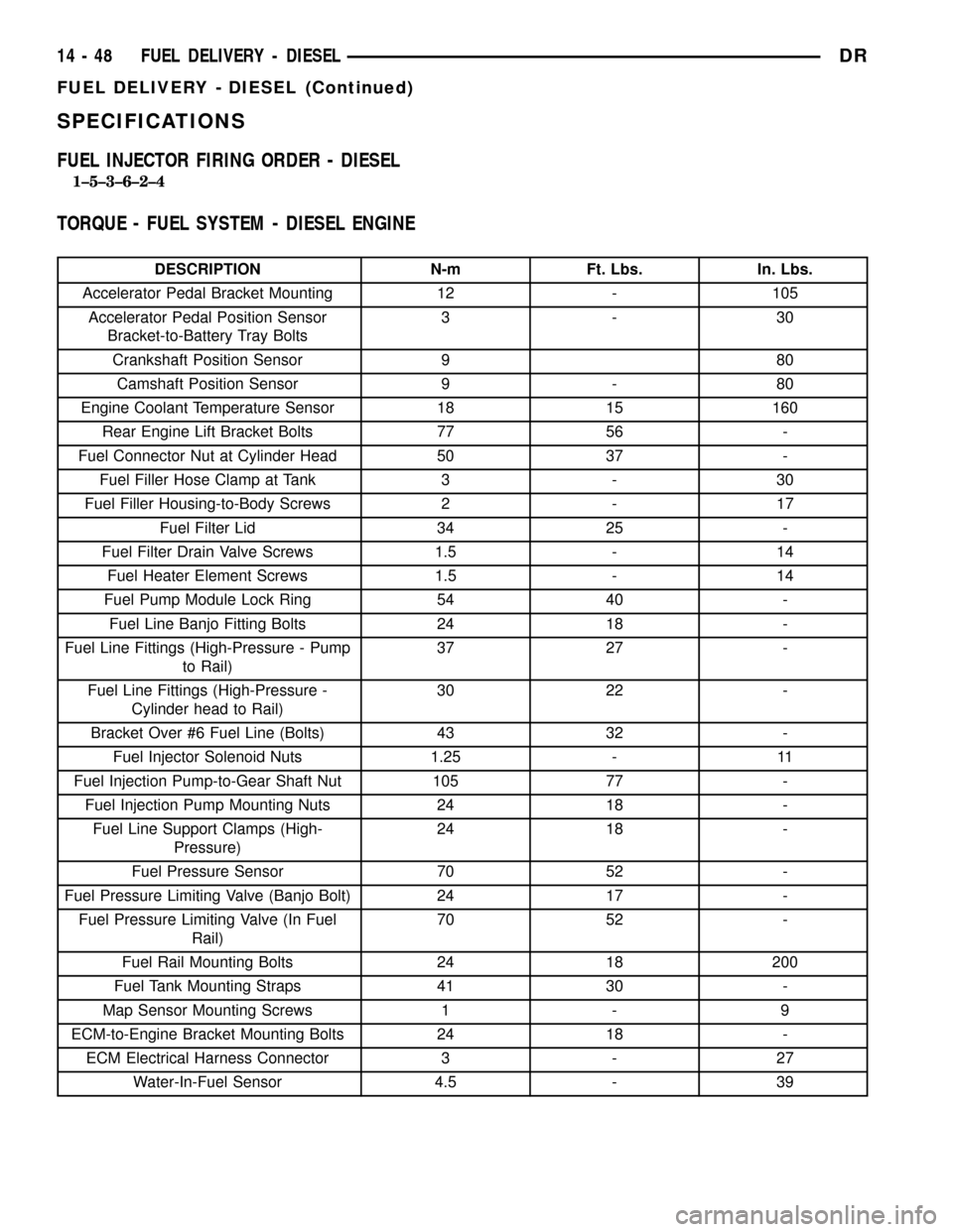
SPECIFICATIONS
FUEL INJECTOR FIRING ORDER - DIESEL
1±5±3±6±2±4
TORQUE - FUEL SYSTEM - DIESEL ENGINE
DESCRIPTION N-m Ft. Lbs. In. Lbs.
Accelerator Pedal Bracket Mounting 12 - 105
Accelerator Pedal Position Sensor
Bracket-to-Battery Tray Bolts3-30
Crankshaft Position Sensor 9 80
Camshaft Position Sensor 9 - 80
Engine Coolant Temperature Sensor 18 15 160
Rear Engine Lift Bracket Bolts 77 56 -
Fuel Connector Nut at Cylinder Head 50 37 -
Fuel Filler Hose Clamp at Tank 3 - 30
Fuel Filler Housing-to-Body Screws 2 - 17
Fuel Filter Lid 34 25 -
Fuel Filter Drain Valve Screws 1.5 - 14
Fuel Heater Element Screws 1.5 - 14
Fuel Pump Module Lock Ring 54 40 -
Fuel Line Banjo Fitting Bolts 24 18 -
Fuel Line Fittings (High-Pressure - Pump
to Rail)37 27 -
Fuel Line Fittings (High-Pressure -
Cylinder head to Rail)30 22 -
Bracket Over #6 Fuel Line (Bolts) 43 32 -
Fuel Injector Solenoid Nuts 1.25 - 11
Fuel Injection Pump-to-Gear Shaft Nut 105 77 -
Fuel Injection Pump Mounting Nuts 24 18 -
Fuel Line Support Clamps (High-
Pressure)24 18 -
Fuel Pressure Sensor 70 52 -
Fuel Pressure Limiting Valve (Banjo Bolt) 24 17 -
Fuel Pressure Limiting Valve (In Fuel
Rail)70 52 -
Fuel Rail Mounting Bolts 24 18 200
Fuel Tank Mounting Straps 41 30 -
Map Sensor Mounting Screws 1 - 9
ECM-to-Engine Bracket Mounting Bolts 24 18 -
ECM Electrical Harness Connector 3 - 27
Water-In-Fuel Sensor 4.5 - 39
14 - 48 FUEL DELIVERY - DIESELDR
FUEL DELIVERY - DIESEL (Continued)
Page 1620 of 2627

(b) Install new o-ring to canister lid and lubri-
cate o-ring with clean engine oil.
(c) Position new element to canister lid. Place
this assembly into canister by rotating clockwise.
(d) Tighten cap to 34 N´m (25 ft. lbs.) torque. Do
not overtighten cap.
(3)Water-In-Fuel (WIF) Sensor:
(a) Install new o-ring seal to WIF sensor.
(b) Apply a light film of clean oil to o-ring seal.
(c) Install sensor into housing.
(d) Tighten sensor to 2.5 N´m (25 in. lbs.) torque.
(e) Connect electrical connector to WIF sensor.
(4)Fuel Heater Element:
(a) Install fuel heater into fuel filter housing.
(b) Install fuel heater thermostat into fuel filter
housing.
(c) Install fuel heater mounting screws and
tighten to 1-1.5 N´m (13 in. lbs.) torque.
(d) Connect electrical connector to fuel heater
thermostat.
(e) Install new filter cover O-ring onto fuel filter
housing cover and lubricate with clean engine oil.
(f) Tighten fuel filter housing cover (lid) to 34
N´m (25 ft. lbs.).
(5)Drain Valve:
(a) Install 2 new o-rings to valve and filter hous-
ing.
(b) Lubricate with silicon grease.
(c) Install fuel drain valve.
(d) Install 4 mounting screws and tighten to
1±1.5 N´m (8±13 in. lbs.) torque.
(e) Connect drain hose to drain valve.
(6) Start engine and check for leaks.
FUEL HEATER
DESCRIPTION
The fuel heater assembly is located on the side of
the fuel filter housing (Fig. 3).
The heater/element assembly is equipped with a
temperature sensor (thermostat) that senses fuel
temperature. This sensor is attached to the fuel heat-
er/element assembly.
OPERATION
The fuel heater is used to prevent diesel fuel from
waxing during cold weather operation.
When the temperature is below 45 8 degrees F,
the temperature sensor allows current to flow to the
heater element warming the fuel. When the temper-
ature is above 75 8 degrees F, the sensor stops cur-
rent flow to the heater element.
Battery voltage to operate the fuel heater element
is supplied from the ignition switch and through the
fuel heater relay. Also refer to Fuel Heater Relay.
Fig. 3 FILTER HOUSING
1 - FILTER HOUSING
2 - FUEL HEATER AND THERMOSTAT
3 - FUEL HEATER MOUNTING SCREWS
4 - FUEL HEATER ELEC. CONNECTOR
5 - WIF SENSOR
6 - WIF SENSOR ELEC. CONNECTOR
7 - DRAIN HOSE
8 - DRAIN VALVE MOUNTING SCREWS
9 - DRAIN VALVE
Fig. 4 FILTER COVER (LID)
1 - FILTER COVER
2 - ATTACH SOCKET HERE
DRFUEL DELIVERY - DIESEL 14 - 51
FUEL FILTER / WATER SEPARATOR (Continued)
Page 1625 of 2627
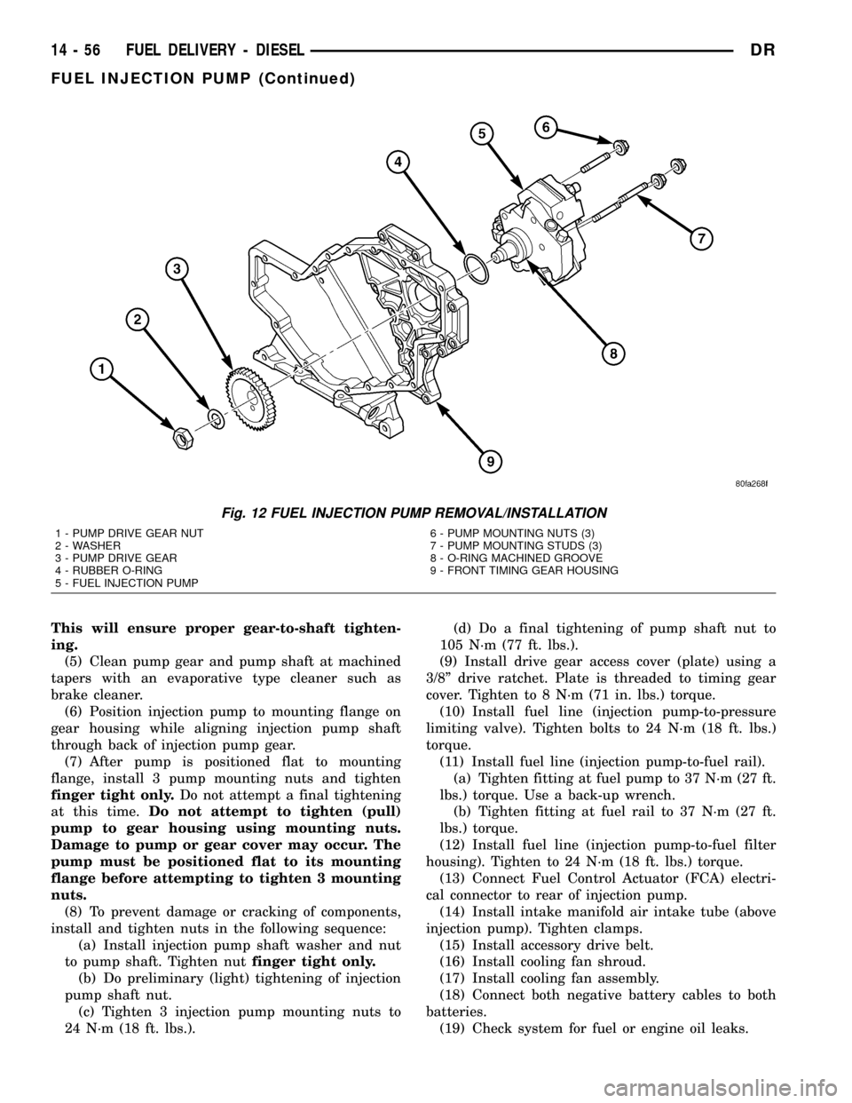
This will ensure proper gear-to-shaft tighten-
ing.
(5) Clean pump gear and pump shaft at machined
tapers with an evaporative type cleaner such as
brake cleaner.
(6) Position injection pump to mounting flange on
gear housing while aligning injection pump shaft
through back of injection pump gear.
(7) After pump is positioned flat to mounting
flange, install 3 pump mounting nuts and tighten
finger tight only.Do not attempt a final tightening
at this time.Do not attempt to tighten (pull)
pump to gear housing using mounting nuts.
Damage to pump or gear cover may occur. The
pump must be positioned flat to its mounting
flange before attempting to tighten 3 mounting
nuts.
(8) To prevent damage or cracking of components,
install and tighten nuts in the following sequence:
(a) Install injection pump shaft washer and nut
to pump shaft. Tighten nutfinger tight only.
(b) Do preliminary (light) tightening of injection
pump shaft nut.
(c) Tighten 3 injection pump mounting nuts to
24 N´m (18 ft. lbs.).(d) Do a final tightening of pump shaft nut to
105 N´m (77 ft. lbs.).
(9) Install drive gear access cover (plate) using a
3/8º drive ratchet. Plate is threaded to timing gear
cover. Tighten to 8 N´m (71 in. lbs.) torque.
(10) Install fuel line (injection pump-to-pressure
limiting valve). Tighten bolts to 24 N´m (18 ft. lbs.)
torque.
(11) Install fuel line (injection pump-to-fuel rail).
(a) Tighten fitting at fuel pump to 37 N´m (27 ft.
lbs.) torque. Use a back-up wrench.
(b) Tighten fitting at fuel rail to 37 N´m (27 ft.
lbs.) torque.
(12) Install fuel line (injection pump-to-fuel filter
housing). Tighten to 24 N´m (18 ft. lbs.) torque.
(13) Connect Fuel Control Actuator (FCA) electri-
cal connector to rear of injection pump.
(14) Install intake manifold air intake tube (above
injection pump). Tighten clamps.
(15) Install accessory drive belt.
(16) Install cooling fan shroud.
(17) Install cooling fan assembly.
(18) Connect both negative battery cables to both
batteries.
(19) Check system for fuel or engine oil leaks.
Fig. 12 FUEL INJECTION PUMP REMOVAL/INSTALLATION
1 - PUMP DRIVE GEAR NUT
2 - WASHER
3 - PUMP DRIVE GEAR
4 - RUBBER O-RING
5 - FUEL INJECTION PUMP6 - PUMP MOUNTING NUTS (3)
7 - PUMP MOUNTING STUDS (3)
8 - O-RING MACHINED GROOVE
9 - FRONT TIMING GEAR HOUSING
14 - 56 FUEL DELIVERY - DIESELDR
FUEL INJECTION PUMP (Continued)
Page 1627 of 2627
WARNING: USE EXTREME CAUTION WHEN
INSPECTING FOR HIGH-PRESSURE FUEL LEAKS.
INSPECT FOR HIGH-PRESSURE FUEL LEAKS WITH
A SHEET OF CARDBOARD. HIGH FUEL INJECTION
PRESSURE CAN CAUSE PERSONAL INJURY IF
CONTACT IS MADE WITH THE SKIN.
DIAGNOSIS AND TESTING - HIGH-PRESSURE
FUEL LINE LEAKS
High-pressure fuel line leaks can cause starting
problems and poor engine performance.
WARNING: DUE TO EXTREME FUEL PRESSURES
OF UP TO 160,000 kPa (23,206 PSI), USE EXTREME
CAUTION WHEN INSPECTING FOR HIGH-PRES-
SURE FUEL LEAKS. DO NOT GET YOUR HAND OR
A FINGER NEAR A SUSPECTED LEAK. INSPECT
FOR HIGH-PRESSURE FUEL LEAKS WITH A SHEET
OF CARDBOARD. HIGH FUEL INJECTION PRES-
SURE CAN CAUSE PERSONAL INJURY IF CON-
TACT IS MADE WITH THE SKIN.
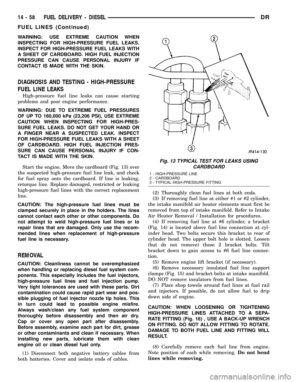
Start the engine. Move the cardboard (Fig. 13) over
the suspected high-pressure fuel line leak, and check
for fuel spray onto the cardboard. If line is leaking,
retorque line. Replace damaged, restricted or leaking
high-pressure fuel lines with the correct replacement
line.
CAUTION: The high-pressure fuel lines must be
clamped securely in place in the holders. The lines
cannot contact each other or other components. Do
not attempt to weld high-pressure fuel lines or to
repair lines that are damaged. Only use the recom-
mended lines when replacement of high-pressure
fuel line is necessary.
REMOVAL
CAUTION: Cleanliness cannot be overemphasized
when handling or replacing diesel fuel system com-
ponents. This especially includes the fuel injectors,
high-pressure fuel lines and fuel injection pump.
Very tight tolerances are used with these parts. Dirt
contamination could cause rapid part wear and pos-
sible plugging of fuel injector nozzle tip holes. This
in turn could lead to possible engine misfire.
Always wash/clean any fuel system component
thoroughly before disassembly and then air dry.
Cap or cover any open part after disassembly.
Before assembly, examine each part for dirt, grease
or other contaminants and clean if necessary. When
installing new parts, lubricate them with clean
engine oil or clean diesel fuel only.
(1) Disconnect both negative battery cables from
both batteries. Cover and isolate ends of cables.(2) Thoroughly clean fuel lines at both ends.
(3) If removing fuel line at either #1 or #2 cylinder,
the intake manifold air heater elements must first be
removed from top of intake manifold. Refer to Intake
Air Heater Removal / Installation for procedures.
(4) If removing fuel line at #6 cylinder, a bracket
(Fig. 14) is located above fuel line connection at cyl-
inder head. Two bolts secure this bracket to rear of
cylinder head. The upper bolt hole is slotted. Loosen
(but do not remove) these 2 bracket bolts. Tilt
bracket down to gain access to #6 fuel line connec-
tion.
(5) Remove engine lift bracket (if necessary).
(6) Remove necessary insulated fuel line support
clamps (Fig. 15) and bracket bolts at intake manifold.
DO NOT remove insulators from fuel lines.
(7) Place shop towels around fuel lines at fuel rail
and injectors. If possible, do not allow fuel to drip
down side of engine.
CAUTION: WHEN LOOSENING OR TIGHTENING
HIGH-PRESSURE LINES ATTACHED TO A SEPA-
RATE FITTING (Fig. 16) , USE A BACK-UP WRENCH
ON FITTING. DO NOT ALLOW FITTING TO ROTATE.
DAMAGE TO BOTH FUEL LINE AND FITTING WILL
RESULT.
(8) Carefully remove each fuel line from engine.
Note position of each while removing.Do not bend
lines while removing.
Fig. 13 TYPICAL TEST FOR LEAKS USING
CARDBOARD
1 - HIGH-PRESSURE LINE
2 - CARDBOARD
3 - TYPICAL HIGH-PRESSURE FITTING
14 - 58 FUEL DELIVERY - DIESELDR
FUEL LINES (Continued)