1998 DODGE RAM 1500 stop start
[x] Cancel search: stop startPage 1580 of 2627
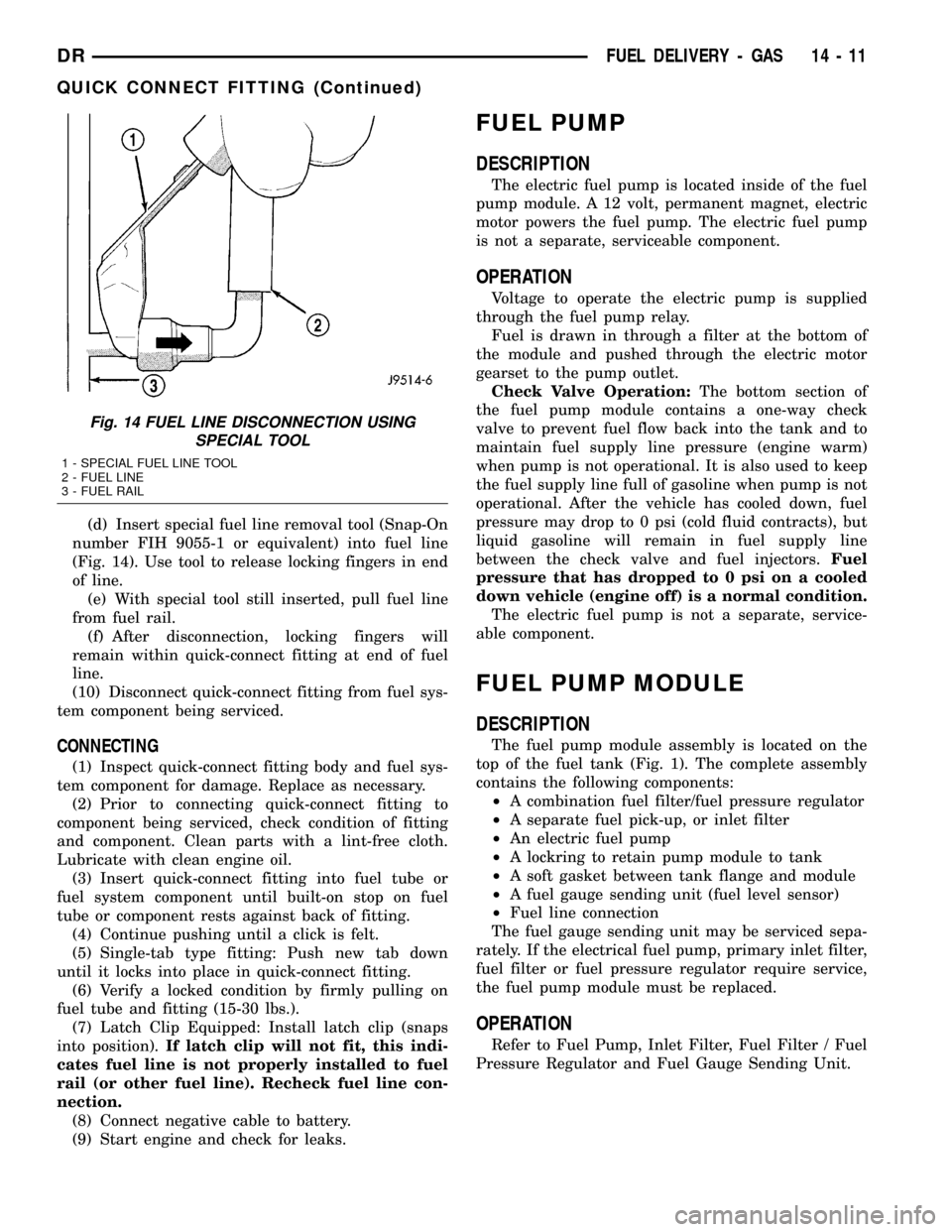
(d) Insert special fuel line removal tool (Snap-On
number FIH 9055-1 or equivalent) into fuel line
(Fig. 14). Use tool to release locking fingers in end
of line.
(e) With special tool still inserted, pull fuel line
from fuel rail.
(f) After disconnection, locking fingers will
remain within quick-connect fitting at end of fuel
line.
(10) Disconnect quick-connect fitting from fuel sys-
tem component being serviced.
CONNECTING
(1) Inspect quick-connect fitting body and fuel sys-
tem component for damage. Replace as necessary.
(2) Prior to connecting quick-connect fitting to
component being serviced, check condition of fitting
and component. Clean parts with a lint-free cloth.
Lubricate with clean engine oil.
(3) Insert quick-connect fitting into fuel tube or
fuel system component until built-on stop on fuel
tube or component rests against back of fitting.
(4) Continue pushing until a click is felt.
(5) Single-tab type fitting: Push new tab down
until it locks into place in quick-connect fitting.
(6) Verify a locked condition by firmly pulling on
fuel tube and fitting (15-30 lbs.).
(7) Latch Clip Equipped: Install latch clip (snaps
into position).If latch clip will not fit, this indi-
cates fuel line is not properly installed to fuel
rail (or other fuel line). Recheck fuel line con-
nection.
(8) Connect negative cable to battery.
(9) Start engine and check for leaks.
FUEL PUMP
DESCRIPTION
The electric fuel pump is located inside of the fuel
pump module. A 12 volt, permanent magnet, electric
motor powers the fuel pump. The electric fuel pump
is not a separate, serviceable component.
OPERATION
Voltage to operate the electric pump is supplied
through the fuel pump relay.
Fuel is drawn in through a filter at the bottom of
the module and pushed through the electric motor
gearset to the pump outlet.
Check Valve Operation:The bottom section of
the fuel pump module contains a one-way check
valve to prevent fuel flow back into the tank and to
maintain fuel supply line pressure (engine warm)
when pump is not operational. It is also used to keep
the fuel supply line full of gasoline when pump is not
operational. After the vehicle has cooled down, fuel
pressure may drop to 0 psi (cold fluid contracts), but
liquid gasoline will remain in fuel supply line
between the check valve and fuel injectors.Fuel
pressure that has dropped to 0 psi on a cooled
down vehicle (engine off) is a normal condition.
The electric fuel pump is not a separate, service-
able component.
FUEL PUMP MODULE
DESCRIPTION
The fuel pump module assembly is located on the
top of the fuel tank (Fig. 1). The complete assembly
contains the following components:
²A combination fuel filter/fuel pressure regulator
²A separate fuel pick-up, or inlet filter
²An electric fuel pump
²A lockring to retain pump module to tank
²A soft gasket between tank flange and module
²A fuel gauge sending unit (fuel level sensor)
²Fuel line connection
The fuel gauge sending unit may be serviced sepa-
rately. If the electrical fuel pump, primary inlet filter,
fuel filter or fuel pressure regulator require service,
the fuel pump module must be replaced.
OPERATION
Refer to Fuel Pump, Inlet Filter, Fuel Filter / Fuel
Pressure Regulator and Fuel Gauge Sending Unit.
Fig. 14 FUEL LINE DISCONNECTION USING
SPECIAL TOOL
1 - SPECIAL FUEL LINE TOOL
2 - FUEL LINE
3 - FUEL RAIL
DRFUEL DELIVERY - GAS 14 - 11
QUICK CONNECT FITTING (Continued)
Page 1616 of 2627

STANDARD PROCEDURE
STANDARD PROCEDURES - WATER DRAINING
AT FUEL FILTER
Refer to Fuel Filter/Water Separator removal/in-
stallation for procedures.
STANDARD PROCEDURES - CLEANING FUEL
SYSTEM PARTS
CAUTION: Cleanliness cannot be overemphasized
when handling or replacing diesel fuel system com-
ponents. This especially includes the fuel injectors,
high-pressure fuel lines and fuel injection pump.
Very tight tolerances are used with these parts. Dirt
contamination could cause rapid part wear and pos-
sible plugging of fuel injector nozzle tip holes. This
in turn could lead to possible engine misfire.
Always wash/clean any fuel system component
thoroughly before disassembly and then air dry.
Cap or cover any open part after disassembly.
Before assembly, examine each part for dirt, grease
or other contaminants and clean if necessary. When
installing new parts, lubricate them with clean
engine oil or clean diesel fuel only.
STANDARD PROCEDURE - FUEL SYSTEM
PRIMING
A certain amount of air becomes trapped in the
fuel system when fuel system components on the
supply and/or high-pressure side are serviced or
replaced. Fuel system priming is accomplished using
the electric fuel transfer (lift) pump.
Servicing or replacing fuel system components will
not require fuel system priming.
The fuel transfer (lift) pump is self-priming: When
the key is first turned on (without cranking engine),
the pump operates for approximately 1 to 2 second
and then shuts off. The pump will also operate for up
to 25 seconds after the starter is quickly engaged,
and then disengaged without allowing the engine to
start. The pump shuts off immediately if the key is
on and the engine stops running.
(1) Turn key to CRANK position and quickly
release key to ON position before engine starts. This
will operate fuel transfer pump for approximately 25
seconds.
(2) Crank engine. If the engine does not start after
25 seconds, turn key OFF. Repeat previous step until
engine starts.
(3) Fuel system priming is now completed.
(4) Attempt to start engine. If engine will not
start, proceed to following steps.When engine does
start, it may run erratically and be noisy for a
few minutes. This is a normal condition.
CAUTION: Do not engage the starter motor for more
than 30 seconds at a time. Allow two minutes
between cranking intervals.
(5) Perform previous fuel priming procedure steps
using fuel transfer pump. Be sure fuel is present at
fuel tank.
(6) Crank the engine for 30 seconds at a time to
allow fuel system to prime.
WARNING: THE FUEL INJECTION PUMP SUPPLIES
EXTREMELY HIGH FUEL PRESSURE TO EACH INDI-
VIDUAL INJECTOR THROUGH THE HIGH-PRES-
SURE LINES. FUEL UNDER THIS AMOUNT OF
PRESSURE CAN PENETRATE THE SKIN AND
CAUSE PERSONAL INJURY. WEAR SAFETY GOG-
GLES AND ADEQUATE PROTECTIVE CLOTHING.
DO NOT LOOSEN FUEL FITTINGS WHILE ENGINE
IS RUNNING.
WARNING: ENGINE MAY START WHILE CRANKING
STARTER MOTOR.
Fig. 2 FUEL INJECTORS
1 - SOLENOID CONNECTIONS
2 - ROCKER HOUSING
3 - FUEL INJECTOR
4 - PASSTHROUGH CONNECTOR
DRFUEL DELIVERY - DIESEL 14 - 47
FUEL DELIVERY - DIESEL (Continued)
Page 1620 of 2627

(b) Install new o-ring to canister lid and lubri-
cate o-ring with clean engine oil.
(c) Position new element to canister lid. Place
this assembly into canister by rotating clockwise.
(d) Tighten cap to 34 N´m (25 ft. lbs.) torque. Do
not overtighten cap.
(3)Water-In-Fuel (WIF) Sensor:
(a) Install new o-ring seal to WIF sensor.
(b) Apply a light film of clean oil to o-ring seal.
(c) Install sensor into housing.
(d) Tighten sensor to 2.5 N´m (25 in. lbs.) torque.
(e) Connect electrical connector to WIF sensor.
(4)Fuel Heater Element:
(a) Install fuel heater into fuel filter housing.
(b) Install fuel heater thermostat into fuel filter
housing.
(c) Install fuel heater mounting screws and
tighten to 1-1.5 N´m (13 in. lbs.) torque.
(d) Connect electrical connector to fuel heater
thermostat.
(e) Install new filter cover O-ring onto fuel filter
housing cover and lubricate with clean engine oil.
(f) Tighten fuel filter housing cover (lid) to 34
N´m (25 ft. lbs.).
(5)Drain Valve:
(a) Install 2 new o-rings to valve and filter hous-
ing.
(b) Lubricate with silicon grease.
(c) Install fuel drain valve.
(d) Install 4 mounting screws and tighten to
1±1.5 N´m (8±13 in. lbs.) torque.
(e) Connect drain hose to drain valve.
(6) Start engine and check for leaks.
FUEL HEATER
DESCRIPTION
The fuel heater assembly is located on the side of
the fuel filter housing (Fig. 3).
The heater/element assembly is equipped with a
temperature sensor (thermostat) that senses fuel
temperature. This sensor is attached to the fuel heat-
er/element assembly.
OPERATION
The fuel heater is used to prevent diesel fuel from
waxing during cold weather operation.
When the temperature is below 45 8 degrees F,
the temperature sensor allows current to flow to the
heater element warming the fuel. When the temper-
ature is above 75 8 degrees F, the sensor stops cur-
rent flow to the heater element.
Battery voltage to operate the fuel heater element
is supplied from the ignition switch and through the
fuel heater relay. Also refer to Fuel Heater Relay.
Fig. 3 FILTER HOUSING
1 - FILTER HOUSING
2 - FUEL HEATER AND THERMOSTAT
3 - FUEL HEATER MOUNTING SCREWS
4 - FUEL HEATER ELEC. CONNECTOR
5 - WIF SENSOR
6 - WIF SENSOR ELEC. CONNECTOR
7 - DRAIN HOSE
8 - DRAIN VALVE MOUNTING SCREWS
9 - DRAIN VALVE
Fig. 4 FILTER COVER (LID)
1 - FILTER COVER
2 - ATTACH SOCKET HERE
DRFUEL DELIVERY - DIESEL 14 - 51
FUEL FILTER / WATER SEPARATOR (Continued)
Page 1621 of 2627

The fuel heater element and fuel heater relay
are not computer controlled.
The heater element operates on 12 volts, 300 watts
at 0 degrees F.
DIAGNOSIS AND TESTING - FUEL HEATER
The fuel heater is used to prevent diesel fuel from
waxing during cold weather operation.
NOTE: The fuel heater element, fuel heater relay
and fuel heater temperature sensor are not con-
trolled by the Engine Control Module (ECM).
A malfunctioning fuel heater can cause a wax
build-up in the fuel filter/water separator. Wax
build-up in the filter/separator can cause engine
starting problems and prevent the engine from rev-
ving up. It can also cause blue or white fog-like
exhaust. If the heater is not operating in cold tem-
peratures, the engine may not operate due to fuel
waxing.
The fuel heater assembly is located on the side of
fuel filter housing.
The heater assembly is equipped with a built-in
fuel temperature sensor (thermostat) that senses fuel
temperature. When fuel temperature drops below 45
degrees 8 degrees F, the sensor allows current to
flow to built-in heater element to warm fuel. When
fuel temperature rises above 75 degrees 8 degrees
F, the sensor stops current flow to heater element
(circuit is open).
Voltage to operate fuel heater element is supplied
from ignition switch, through fuel heater relay (also
refer to Fuel Heater Relay), to fuel temperature sen-
sor and on to fuel heater element.
The heater element operates on 12 volts, 300 watts
at 0 degrees F. As temperature increases, power
requirements decrease.
A minimum of 7 volts is required to operate the
fuel heater. The resistance value of the heater ele-
ment is less than 1 ohm (cold) and up to 1000 ohms
warm.
TESTING
(1) Disconnect electrical connector from thermostat
(Fig. 3).
Ambient temperature must be below the circuit
close temperature. If necessary, induce this ambient
temperature by placing ice packs on thermostat to
produce an effective ambient temperature below cir-
cuit close temperature.
Measure resistance across two pins. Operating
range is 0.3 Ð 0.45 Ohms.
(2) If resistance is out of range, remove thermostat
and check resistance across terminal connections of
heater. The heater can be checked at room tempera-
ture. Operating range is 0.3 - 0.45 Ohms.(3) Replace heater if resistance is not within oper-
ating range.
(4) If heater is within operating range, replace
heater thermostat.
REMOVAL
REMOVAL/INSTALLATION
The fuel heater/element/sensor assembly is located
inside of the fuel filter housing. Refer to Fuel Filter/
Water Separator Removal/Installation for procedures.
FUEL HEATER RELAY
DESCRIPTION
The fuel heater relay is located in Power Distribu-
tion Center (PDC) (Fig. 5). Refer to label on inside of
PDC cover for relay location.
OPERATION
Battery voltage to operate the fuel heater element
is supplied from the ignition switch through the fuel
heater relay.The fuel heater element and fuel
heater relay are not computer controlled.
REMOVAL
The fuel heater relay is located in the Power Dis-
tribution Center (PDC) (Fig. 6). Refer to label under
PDC cover for relay location.
(1) Remove PDC cover.
(2) Remove relay from PDC.
Fig. 5 POWER DISTRIBUTION CENTER LOCATION
1 - CLIP
2 - BATTERY
3 - TRAY
4 - NEGATIVE CABLE
5 - POSITIVE CABLE
6 - CLIP
7 - FENDER INNER SHIELD
8 - POWER DISTRIBUTION CENTER
14 - 52 FUEL DELIVERY - DIESELDR
FUEL HEATER (Continued)
Page 1633 of 2627
INSTALLATION
CAUTION: Whenever the fuel tank module is ser-
viced, the rubber gasket must be replaced.
(1) Thoroughly clean locknut and locknut threads
at top of tank.(2) Using new gasket, carefully position fuel tank
module into opening in fuel tank.
(3) Position locknut over top of fuel tank module.
Install locknut finger tight.
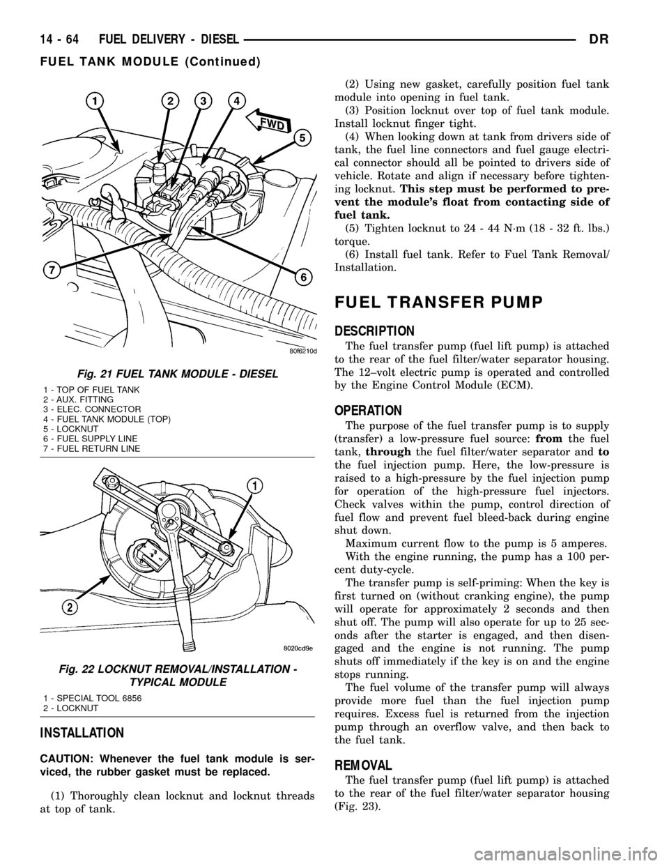
(4) When looking down at tank from drivers side of
tank, the fuel line connectors and fuel gauge electri-
cal connector should all be pointed to drivers side of
vehicle. Rotate and align if necessary before tighten-
ing locknut.This step must be performed to pre-
vent the module's float from contacting side of
fuel tank.
(5) Tighten locknut to 24 - 44 N´m (18 - 32 ft. lbs.)
torque.
(6) Install fuel tank. Refer to Fuel Tank Removal/
Installation.
FUEL TRANSFER PUMP
DESCRIPTION
The fuel transfer pump (fuel lift pump) is attached
to the rear of the fuel filter/water separator housing.
The 12±volt electric pump is operated and controlled
by the Engine Control Module (ECM).
OPERATION
The purpose of the fuel transfer pump is to supply
(transfer) a low-pressure fuel source:fromthe fuel
tank,throughthe fuel filter/water separator andto
the fuel injection pump. Here, the low-pressure is
raised to a high-pressure by the fuel injection pump
for operation of the high-pressure fuel injectors.
Check valves within the pump, control direction of
fuel flow and prevent fuel bleed-back during engine
shut down.
Maximum current flow to the pump is 5 amperes.
With the engine running, the pump has a 100 per-
cent duty-cycle.
The transfer pump is self-priming: When the key is
first turned on (without cranking engine), the pump
will operate for approximately 2 seconds and then
shut off. The pump will also operate for up to 25 sec-
onds after the starter is engaged, and then disen-
gaged and the engine is not running. The pump
shuts off immediately if the key is on and the engine
stops running.
The fuel volume of the transfer pump will always
provide more fuel than the fuel injection pump
requires. Excess fuel is returned from the injection
pump through an overflow valve, and then back to
the fuel tank.
REMOVAL
The fuel transfer pump (fuel lift pump) is attached
to the rear of the fuel filter/water separator housing
(Fig. 23).
Fig. 21 FUEL TANK MODULE - DIESEL
1 - TOP OF FUEL TANK
2 - AUX. FITTING
3 - ELEC. CONNECTOR
4 - FUEL TANK MODULE (TOP)
5 - LOCKNUT
6 - FUEL SUPPLY LINE
7 - FUEL RETURN LINE
Fig. 22 LOCKNUT REMOVAL/INSTALLATION -
TYPICAL MODULE
1 - SPECIAL TOOL 6856
2 - LOCKNUT
14 - 64 FUEL DELIVERY - DIESELDR
FUEL TANK MODULE (Continued)
Page 1644 of 2627
The torquing force of this threaded nut (fitting)
provides a sealing pressure between the fuel line con-
nector and the fuel injector.Retaining nut torque
is very critical.If the nut (fitting) is under torqued,
the mating surfaces will not seal and a high-pressure
fuel leak will result. If the fitting is over torqued, the
connector and injector will deform and also cause a
high-pressure fuel leak. This leak will be inside the
cylinder head and will not be visible. The result will
be a possible fuel injector miss-fire and low power, or
a no-start condition.
The fuel injectors use hole type nozzles. High-pres-
sure flows into the side of the injector, the ECM acti-
vates the solenoid causing the injector needle to lift
and fuel to be injected. The clearances in the nozzle
bore are extremely small and any dirt or contami-
nants will cause the injector to stick. Because of this,
it is very important to do a thorough cleaning of any
lines before opening up any fuel system component.
Always cover or cap any open fuel connections before
a fuel system repair is performed.
Each fuel injector connector tube contains an edge
filter that is designed to beak up small contaminants
before entering the fuel injector.The edge filters
are not a substitute for proper cleaning andcovering of all fuel system components during
repair.
The bottom of each fuel injector is sealed to the
cylinder head with a1.5mmthick copper shim (gas-
ket). The correct thickness shim must always be re-
installed after removing an injector.
Fuel pressure in the injector circuit decreases after
injection. The injector needle valve is immediately
closed and fuel flow into the combustion chamber is
stopped. Exhaust gases are prevented from entering
the injector nozzle by the needle valve.
REMOVAL
CAUTION: Refer to Cleaning Fuel System Parts.
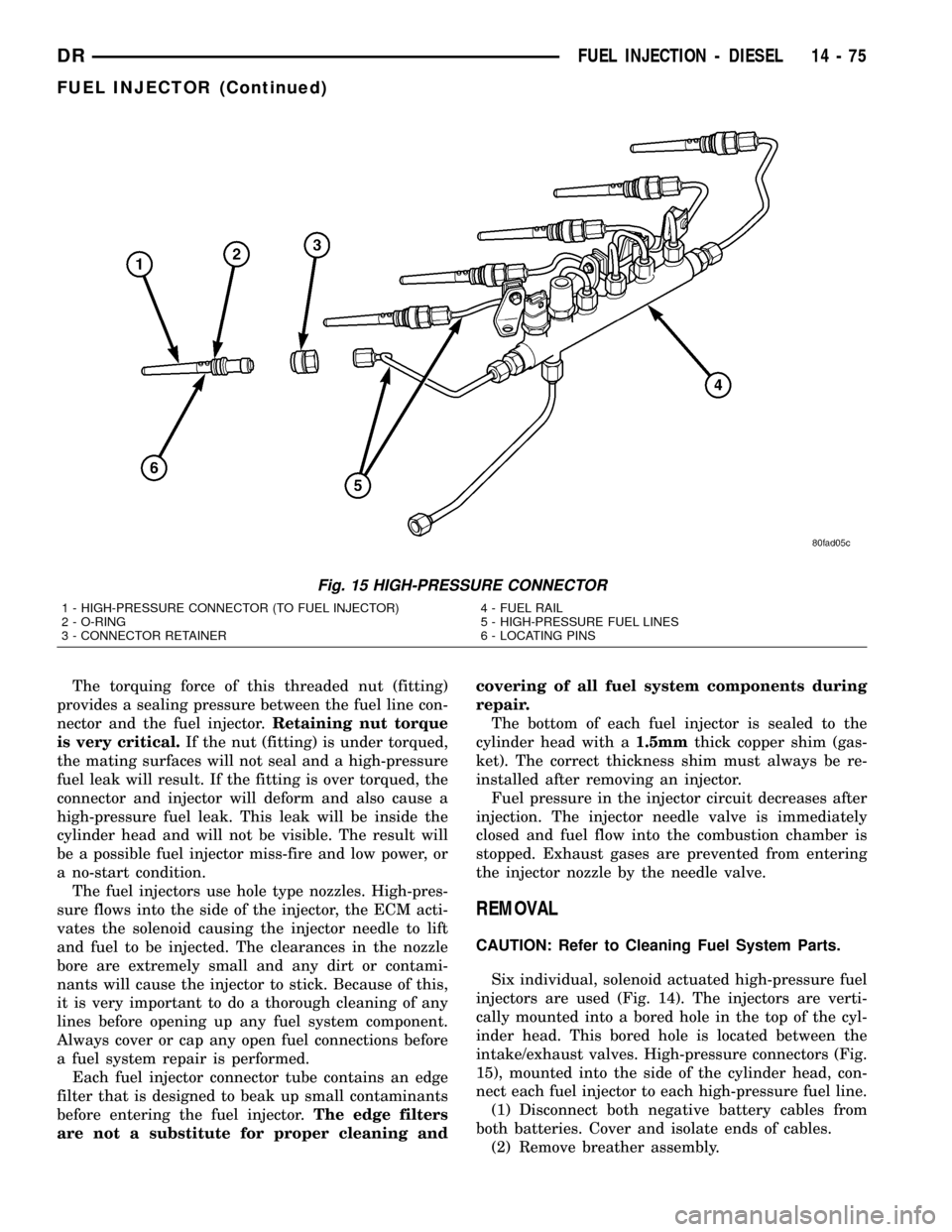
Six individual, solenoid actuated high-pressure fuel
injectors are used (Fig. 14). The injectors are verti-
cally mounted into a bored hole in the top of the cyl-
inder head. This bored hole is located between the
intake/exhaust valves. High-pressure connectors (Fig.
15), mounted into the side of the cylinder head, con-
nect each fuel injector to each high-pressure fuel line.
(1) Disconnect both negative battery cables from
both batteries. Cover and isolate ends of cables.
(2) Remove breather assembly.
Fig. 15 HIGH-PRESSURE CONNECTOR
1 - HIGH-PRESSURE CONNECTOR (TO FUEL INJECTOR)
2 - O-RING
3 - CONNECTOR RETAINER4 - FUEL RAIL
5 - HIGH-PRESSURE FUEL LINES
6 - LOCATING PINS
DRFUEL INJECTION - DIESEL 14 - 75
FUEL INJECTOR (Continued)
Page 1659 of 2627
DIAGNOSIS AND TESTING - POWER STEERING
FLOW AND PRESSURE
The following procedure is used to test the opera-
tion of the power steering system on the vehicle. This
test will provide the gallons per minute (GPM) or
flow rate of the power steering pump along with the
maximum relief pressure. Perform test any time a
power steering system problem is present. This test
will determine if the power steering pump or power
steering gear is not functioning properly. The follow-
ing pressure and flow test is performed using Power
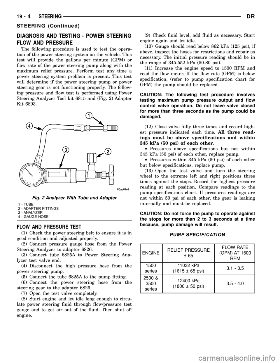
Steering Analyzer Tool kit 6815 and (Fig. 2) Adapter
Kit 6893.
FLOW AND PRESSURE TEST
(1) Check the power steering belt to ensure it is in
good condition and adjusted properly.
(2) Connect pressure gauge hose from the Power
Steering Analyzer to adapter 6826.
(3) Connect tube 6825A to Power Steering Ana-
lyzer test valve end.
(4) Disconnect the high pressure hose from the
power steering pump.
(5) Connect the tube 6825A to the pump fitting.
(6) Connect the power steering hose from the
steering gear to the adapter 6826.
(7) Open the test valve completely.
(8) Start engine and let idle long enough to circu-
late power steering fluid through flow/pressure test
gauge and to get air out of the fluid. Then shut off
engine.(9) Check fluid level, add fluid as necessary. Start
engine again and let idle.
(10) Gauge should read below 862 kPa (125 psi), if
above, inspect the hoses for restrictions and repair as
necessary. The initial pressure reading should be in
the range of 345-552 kPa (50-80 psi).
(11) Increase the engine speed to 1500 RPM and
read the flow meter. If the flow rate (GPM) is below
specification, (refer to pump specification chart for
GPM) the pump should be replaced.
CAUTION: The following test procedure involves
testing maximum pump pressure output and flow
control valve operation. Do not leave valve closed
for more than three seconds as the pump could be
damaged.
(12) Close valve fully three times and record high-
est pressure indicated each time.All three read-
ings must be above specifications and within
345 kPa (50 psi) of each other.
²Pressures above specifications but not within
345 kPa (50 psi) of each other, replace pump.
²Pressures within 345 kPa (50 psi) of each other
but below specifications, replace pump.
(13) Open the test valve and turn the steering
wheel to the extreme left and right positions three
times against the stops. Record the highest pressure
reading at each position. Compare readings to the
pump specifications chart. If pressures readings are
not within 50 psi of each other, the gear is leaking
internally and must be replaced.
CAUTION: Do not force the pump to operate against
the stops for more than 2 to 3 seconds at a time
because, pump damage will result.PUMP SPECIFICATION
ENGINERELIEF PRESSURE
65FLOW RATE
(GPM) AT 1500
RPM
1500
series11032 kPa
(1615 65 psi)3.1 - 3.5
2500 &
3500
series12400 kPa
(1800 50 psi)3.5 - 4.0
Fig. 2 Analyzer With Tube and Adapter
1 - TUBE
2 - ADAPTER FITTINGS
3 - ANALYZER
4 - GAUGE HOSE
19 - 4 STEERINGDR
STEERING (Continued)
Page 1677 of 2627
CAUTION: Do not overtighten the vise on the gear
case. This may affect the adjustment
(3) Hold the steering gear upside down over a
drain pan and rotate the input shaft back and forth
several times lock-to-lock to discharge the fluid from
the steering gear
(4) Rotate the input shaft to the left stop and then
back-off approximately 45 degrees. Using an inch-
pound torque wrench on the input shaft, record the
peak torque required to slowly and evenly rotate the
input shaft clockwise
1¤2turn (180 degrees) starting
from the 45 degree position. This peak torque read-
ing is the preload torque. The preload torque must be
within2-10in-lbs.
(5) Rotate the input shaft to its center of travel
(approximately 1.5 turns from either stop). Place the
torque wrench on the input shaft with the handle in
the vertical position. Rotate the torque wrench slowly
and evenly
1¤4turn (90 degrees) each side of center
and record the peak torque measure on or near cen-ter. This total on-center torque reading must be5-9
in-lbs higher than the previously measured preload
torque without exceeding a total of 17 in-lbs. The
value of the total on-center minus the preload torque
is defined as the meshload torque
(6) If required, adjust the on-center torque by loos-
ening the adjuster screw lock nut and turning the
adjuster screw until the total on-center and meshload
torque readings fall within the specified values. Turn
the adjuster screw clockwise to increase and counter-
clockwise to decrease the torque reading. While hold-
ing the adjuster screw in place, tighten the lock nut
to 31 N´m (23 ft. lbs.).
(7) Re-check the preload and on-center torque
readings.
(8) Install pitman arm on the steering gear (Refer
to 19 - STEERING/LINKAGE/PITMAN ARM -
INSTALLATION).
(9) Reinstall steering gear to the vehicle (Refer to
19 - STEERING/GEAR - INSTALLATION).
SPECIFICATIONS
POWER STEERING GEAR
SPECIFICATIONS
DESCRIPTION SPECIFICATION
Steering Gear
TypeRecirculating Ball
Gear Code & Ratio 12.5:1
TORQUE SPECIFICATIONS
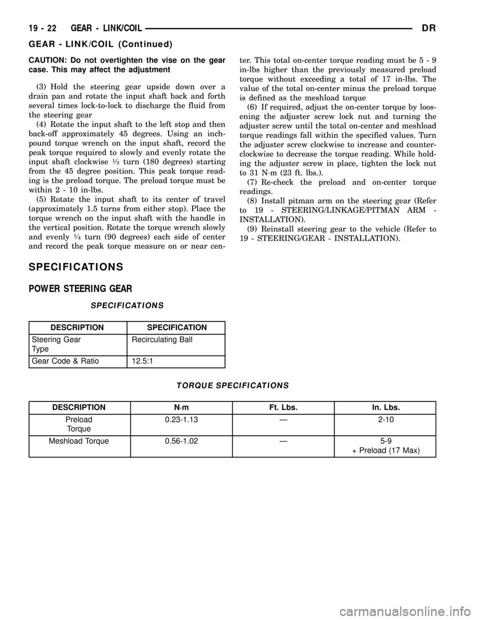
DESCRIPTION N´m Ft. Lbs. In. Lbs.
Preload
Torque0.23-1.13 Ð 2-10
Meshload Torque 0.56-1.02 Ð 5-9
+ Preload (17 Max)
19 - 22 GEAR - LINK/COILDR
GEAR - LINK/COIL (Continued)