1998 DODGE RAM 1500 Rocker arms
[x] Cancel search: Rocker armsPage 1464 of 2627
(10) Drain engine oil. Remove and discard the oil
filter (Refer to 9 - ENGINE/LUBRICATION/OIL FIL-
TER - REMOVAL).
(11) Install the drain plug. Tighten the plug to 50
N´m (37 ft. lbs.) torque.
(12) Install a new oil filter (Refer to 9 - ENGINE/
LUBRICATION/OIL FILTER - INSTALLATION).
(13) Fill engine crankcase with the specified
amount and grade of oil (Refer to LUBRICATION &
MAINTENANCE/FLUID TYPES - SPECIFICA-
TIONS).
(14) Connect the negative cable(s) to the battery.
(15) Start the engine and check for any leaks.
REMOVAL
REMOVAL - ENGINE
(1) Disconnect both battery negative cables.
(2) Disconnect engine grid heater harness at grid
heater relays.
(3) Disconnect electrical connections from rear of
alternator.
(4) Recover A/C refrigerant. (Refer to 24 - HEAT-
ING & AIR CONDITIONING/PLUMBING - STAN-
DARD PROCEDURE).
(5) Raise vehicle on a hoist.
(6) Drain engine coolant (Refer to 7 - COOLING -
STANDARD PROCEDURE).
(7) Remove engine oil drain plug and drain engine
oil.
(8) Reinstall drain plug. Tighten to 50N´m (37 ft.
lbs.) torque.
(9) Lower the vehicle.
(10) Remove fan/drive assembly. Refer to Section 7
± Fan/Drive Removal
(11) Remove radiator upper hose.
(12) Remove upper fan shroud mounting bolts.
(13) Disconnect the coolant recovery bottle hose
from the radiator fill neck and remove bottle.
(14) Using a 36mm wrench, remove viscous fan/
drive assembly. (Refer to 7 - COOLING/ENGINE/RA-
DIATOR FAN - REMOVAL).
(15) Remove cooling fan and shroud together.
(16) Disconnect heater core supply and return
hoses from the cylinder head fitting and coolant pipe.
(17) Raise vehicle on a hoist.
(18) Remove transmission and transfer case (if
equipped).
(19) Disconnect exhaust pipe from turbocharger
extension pipe.
(20) Disconnect engine harness to vehicle harness
connectors.
(21) Remove starter motor (Refer to 8 - ELECTRI-
CAL/STARTING/STARTER MOTOR - REMOVAL).(22) Remove flywheel/flexplate.
(23) Remove transmission adapter
(24) Disconnect A/C suction/discharge hose from
the rear of the A/C compressor.
(25) Lower vehicle.
(26) Disconnect lower radiator hose from radiator
outlet.
(27) Automatic transmission models:
(28) Disconnect transmission oil cooler lines from
in front of radiator using special tool #6931
(29) Remove radiator. (Refer to 7 - COOLING/EN-
GINE/RADIATOR - REMOVAL).
(30) If A/C equipped, disconnect A/C condenser
refrigerant lines.
(31) Disconnect charge air cooler piping.
(32) Remove charge air cooler mounting bolts.
(33) Remove charge air cooler (and A/C condenser
if equipped) from vehicle.
(34) Remove damper and speed indicator ring from
front of engine.
(35) Disconnect engine block heater connector.
(36) Disconnect A/C compressor and pressure sen-
sor electrical connectors.
(37) Remove the passenger battery ground cable
from the engine block. Remove the driver side bat-
tery ground cable from the engine block.
(38) Remove power steering pump from engine by
removing 3 bolts.
(39) Remove accelerator linkage cover.
(40) Disconnect cables from on-engine APPS.
(41) Disconnect the ECM power connector.
(42) Disconnect the ECM ground wire from the
hydroform screw.
(43) Disconnect the fuel supply and return hoses.
(44) Remove the cylinder head cover. (Refer to 9 -
ENGINE/CYLINDER HEAD/CYLINDER HEAD
COVER(S) - REMOVAL).
(45) Disconnect the 3 injector harness connectors
at the rocker housing. Disconnect the wire harnesses
from the injectors.
(46) Remove the rear engine lift bracket.
(47) Remove cylinder #4, #5, and #6 intake and
exhaust rocker arms, pedestals, and push tubes. Note
the original location for re-assembly.
(48) Loosen #6 fuel line shield bolts and rotate
shield out of the way.
(49) Remove cylinder #5 and #6 high pressure fuel
lines. Remove the fuel connector tube nut and fuel
connector tube. Remove cylinder #5 and #6 fuel injec-
tor.
(50) Remove rocker housing.
DRENGINE 5.9L DIESEL 9 - 241
ENGINE 5.9L DIESEL (Continued)
Page 1466 of 2627
(8) Replace injector o-ring and sealing washer on
injectors #5 and #6. Install injectors and torque using
the following steps:
²Step 1ÐInstall injector hold-down capscrews
and torque to 5 N´m (44 in. lbs.) torque.
²Step 2ÐLoosen injector hold-down capscrews.
²Step 3ÐInstall HPC connector tube and nut.
Torque nut to 15 N´m (11 ft. lbs.) torque.
²Step 4ÐTorque injector hold-down capscrews to
10 N´m (89 in. lbs.) torque.
²Step 5ÐTorque HPC connector tube nut to 50
N´m (37 ft. lbs.) torque.
(9) Install #5 and #6 high pressure fuel lines. Fol-
low correct torque sequence per section 14. Torque
fuel line fittings to 30 N-m (22 ft-lb). Torque brace
capscrew to 24 N-m (18 ft-lb).
(10) Install rear engine lift bracket. Torque to 77
N-m (57 ft-lb).
(11) Install push tubes, rocker arms, and pedestals
for cylinders #4, #5, and #6. Torque the mounting
bolts to 36 N-m (27 ft-lbs).
(12) Reset valve lash on cylinders #4, #5, and #6.
Torque adjusting nuts to 24 N-m (18 ft-lbs).
(13) Install cylinder head cover. Torque to 24 N-m
(18 ft-lbs).(Refer to 9 - ENGINE/CYLINDER HEAD -
INSTALLATION).
(14) Connect breather tube and lube oil drain tube
to breather housing cover. Install breather housing.
Torque capscrews to 24 N-m (18 ft-lbs)
(15) Connect fuel supply and return hoses.
(16) Connect ECM ground to hydroform screw.
Connect ECM power connector.
(17) Install the APPS cable(s) to the APPS. Install
the throttle linkage cover.
(18) Install the power steering pump.
(19) Install the damper and speed indicator ring.
Torque to 40 N-m (30 ft-lb) plus 60 degrees.
(20) Connect the engine block heater connection.
(21) Connect the A/C compressor and pressure sen-
sor connectors
(22) Install the charge air cooler and a/c condenser
(if equipped). Install and tighten the charge air
cooler mounting bolts to 2 N-m (17 in-lbs).
(23) Connect the charge air cooler piping. Torque
all clamps to 8 N-m (72 in-lbs).
(24) Connect the a/c refrigerant lines to the a/c
condenser (if equipped).
(25) Install the radiator upper support panel.
(26) Install radiator.
(27) Connect the transmission quick-connect oil
cooler lines.(28) Raise vehicle.
(29) Connect a/c compressor suction/discharge hose
(if equipped).
(30) Install the radiator lower hose and clamps.
(31) Install the battery negative cables to the
engine block on the driver and passenger side.
(32) Install the transmission adapter with a new
camshaft rectangular ring seal. Torque to 77 N-m (57
ft-lb).
(33) Install the flywheel/flexplate. Torque to 137
N-m (101 ft-lb).
(34) Install the starter motor. Torque to 43 N-m
(32 ft-lb). (Refer to 8 - ELECTRICAL/STARTING/
STARTER MOTOR - INSTALLATION).
(35) Connect engine to vehicle harness connectors.
(36) Install transmission and transfer case (if
equipped).
(37) Connect the exhaust pipe to the turbocharger
elbow.
(38) Connect the transmission auxiliary oil cooler
lines (if equipped).
(39) Lower the vehicle.
(40) Connect the heater core supply and return
hoses.
(41) Install the cooling fan and upper fan shroud
at the same time. (Refer to 7 - COOLING/ENGINE/
RADIATOR FAN - INSTALLATION).
(42) Install the coolant recovery bottle.
(43) Install the windshield washer bottle.
(44) Install the upper radiator hose and clamps.
(45) Raise vehicle.
(46) Connect electronically controlled fan drive
wire harness. Install lower radiator fan shroud.
(47) Change oil filter and install new engine oil.
(48) Fill the cooling system with coolant. (Refer to
7 - COOLING - STANDARD PROCEDURE).
(49) Connect grid heater harness at grid heater
relays.
(50) Connect electrical connections to rear of alter-
nator.
(51) Start the engine and inspect for engine oil,
coolant, and fuel leaks.
INSTALLATIONÐCRANKCASE BREATHER
(1) Install a new o-ring onto the breather element.
(2) Lubricate o-ring and install into cylinder head
cover. Torque capscrews to 10 N´m (89 in. lbs.).
(3) Connect breather tube and lube oil drain tube.
(4) Install breather cover (Fig. 4). Torque to 24
N´m (18 ft. lbs.)
(5) Install oil fill cap.
DRENGINE 5.9L DIESEL 9 - 243
ENGINE 5.9L DIESEL (Continued)
Page 1476 of 2627
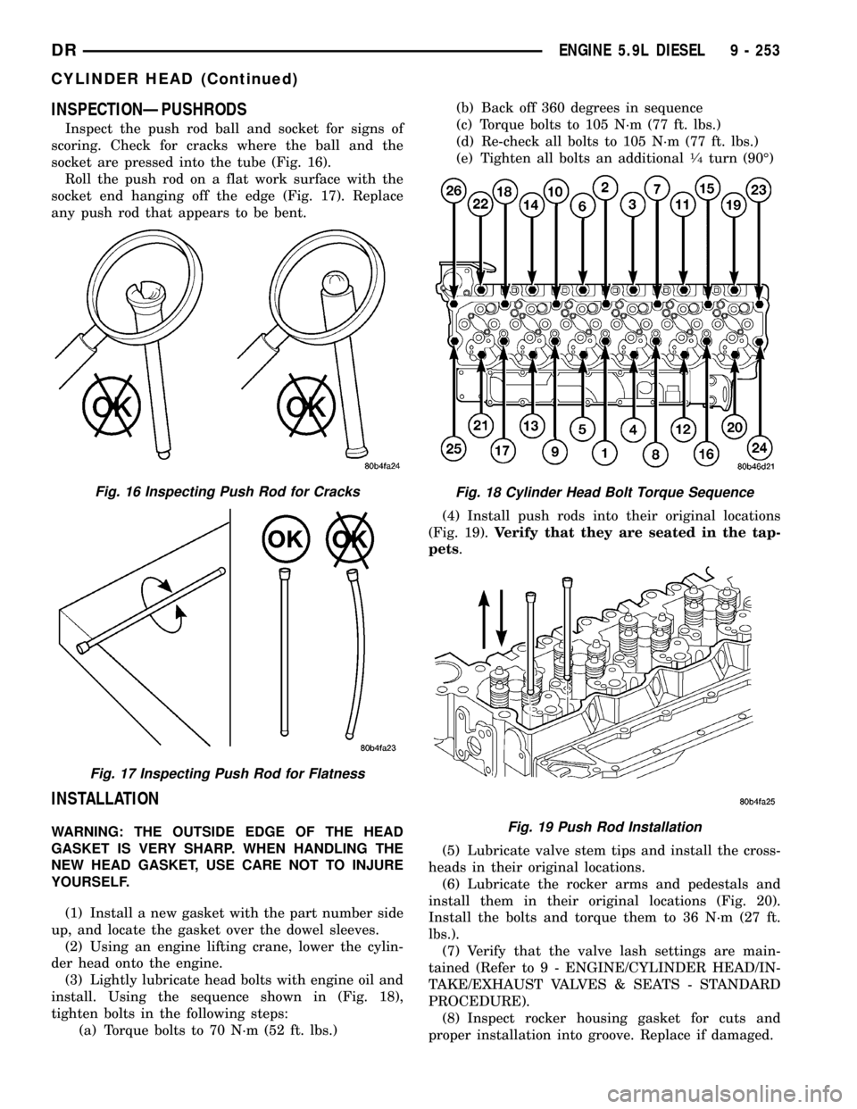
INSPECTIONÐPUSHRODS
Inspect the push rod ball and socket for signs of
scoring. Check for cracks where the ball and the
socket are pressed into the tube (Fig. 16).
Roll the push rod on a flat work surface with the
socket end hanging off the edge (Fig. 17). Replace
any push rod that appears to be bent.
INSTALLATION
WARNING: THE OUTSIDE EDGE OF THE HEAD
GASKET IS VERY SHARP. WHEN HANDLING THE
NEW HEAD GASKET, USE CARE NOT TO INJURE
YOURSELF.
(1) Install a new gasket with the part number side
up, and locate the gasket over the dowel sleeves.
(2) Using an engine lifting crane, lower the cylin-
der head onto the engine.
(3) Lightly lubricate head bolts with engine oil and
install. Using the sequence shown in (Fig. 18),
tighten bolts in the following steps:
(a) Torque bolts to 70 N´m (52 ft. lbs.)(b) Back off 360 degrees in sequence
(c) Torque bolts to 105 N´m (77 ft. lbs.)
(d) Re-check all bolts to 105 N´m (77 ft. lbs.)
(e) Tighten all bolts an additional
1¤4turn (90É)
(4) Install push rods into their original locations
(Fig. 19).Verify that they are seated in the tap-
pets.
(5) Lubricate valve stem tips and install the cross-
heads in their original locations.
(6) Lubricate the rocker arms and pedestals and
install them in their original locations (Fig. 20).
Install the bolts and torque them to 36 N´m (27 ft.
lbs.).
(7) Verify that the valve lash settings are main-
tained (Refer to 9 - ENGINE/CYLINDER HEAD/IN-
TAKE/EXHAUST VALVES & SEATS - STANDARD
PROCEDURE).
(8) Inspect rocker housing gasket for cuts and
proper installation into groove. Replace if damaged.
Fig. 16 Inspecting Push Rod for Cracks
Fig. 17 Inspecting Push Rod for Flatness
Fig. 18 Cylinder Head Bolt Torque Sequence
Fig. 19 Push Rod Installation
DRENGINE 5.9L DIESEL 9 - 253
CYLINDER HEAD (Continued)
Page 1482 of 2627
INSTALLATION
(1) Install new valve seals. The yellow seals are for
the intake valves and the green seals are for the
exhaust valves.
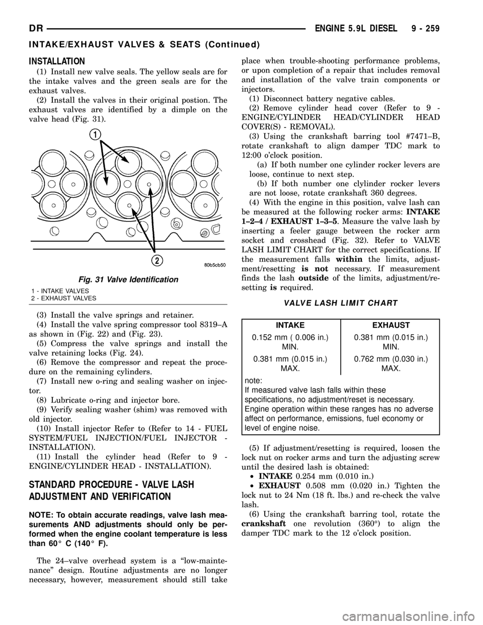
(2) Install the valves in their original postion. The
exhaust valves are identified by a dimple on the
valve head (Fig. 31).
(3) Install the valve springs and retainer.
(4) Install the valve spring compressor tool 8319±A
as shown in (Fig. 22) and (Fig. 23).
(5) Compress the valve springs and install the
valve retaining locks (Fig. 24).
(6) Remove the compressor and repeat the proce-
dure on the remaining cylinders.
(7) Install new o-ring and sealing washer on injec-
tor.
(8) Lubricate o-ring and injector bore.
(9) Verify sealing washer (shim) was removed with
old injector.
(10) Install injector Refer to (Refer to 14 - FUEL
SYSTEM/FUEL INJECTION/FUEL INJECTOR -
INSTALLATION).
(11) Install the cylinder head (Refer to 9 -
ENGINE/CYLINDER HEAD - INSTALLATION).
STANDARD PROCEDURE - VALVE LASH
ADJUSTMENT AND VERIFICATION
NOTE: To obtain accurate readings, valve lash mea-
surements AND adjustments should only be per-
formed when the engine coolant temperature is less
than 60É C (140É F).
The 24±valve overhead system is a ªlow-mainte-
nanceº design. Routine adjustments are no longer
necessary, however, measurement should still takeplace when trouble-shooting performance problems,
or upon completion of a repair that includes removal
and installation of the valve train components or
injectors.
(1) Disconnect battery negative cables.
(2) Remove cylinder head cover (Refer to 9 -
ENGINE/CYLINDER HEAD/CYLINDER HEAD
COVER(S) - REMOVAL).
(3) Using the crankshaft barring tool #7471±B,
rotate crankshaft to align damper TDC mark to
12:00 o'clock position.
(a) If both number one cylinder rocker levers are
loose, continue to next step.
(b) If both number one clylinder rocker levers
are not loose, rotate crankshaft 360 degrees.
(4) With the engine in this position, valve lash can
be measured at the following rocker arms:INTAKE
1±2±4 / EXHAUST 1±3±5. Measure the valve lash by
inserting a feeler gauge between the rocker arm
socket and crosshead (Fig. 32). Refer to VALVE
LASH LIMIT CHART for the correct specifications. If
the measurement fallswithinthe limits, adjust-
ment/resettingis notnecessary. If measurement
finds the lashoutsideof the limits, adjustment/re-
settingisrequired.
VALVE LASH LIMIT CHART
INTAKE EXHAUST
0.152 mm ( 0.006 in.)
MIN.0.381 mm (0.015 in.)
MIN.
0.381 mm (0.015 in.)
MAX.0.762 mm (0.030 in.)
MAX.
note:
If measured valve lash falls within these
specifications, no adjustment/reset is necessary.
Engine operation within these ranges has no adverse
affect on performance, emissions, fuel economy or
level of engine noise.
(5) If adjustment/resetting is required, loosen the
lock nut on rocker arms and turn the adjusting screw
until the desired lash is obtained:
²INTAKE0.254 mm (0.010 in.)
²EXHAUST0.508 mm (0.020 in.) Tighten the
lock nut to 24 Nm (18 ft. lbs.) and re-check the valve
lash.
(6) Using the crankshaft barring tool, rotate the
crankshaftone revolution (360É) to align the
damper TDC mark to the 12 o'clock position.
Fig. 31 Valve Identification
1 - INTAKE VALVES
2 - EXHAUST VALVES
DRENGINE 5.9L DIESEL 9 - 259
INTAKE/EXHAUST VALVES & SEATS (Continued)
Page 1483 of 2627
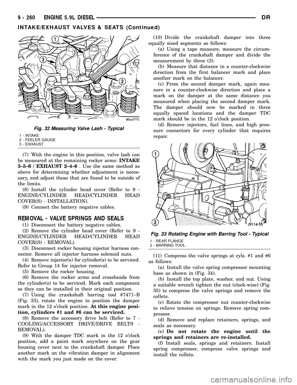
(7) With the engine in this position, valve lash can
be measured at the remaining rocker arms:INTAKE
3±5±6 / EXHAUST 2±4±6. Use the same method as
above for determining whether adjustment is neces-
sary, and adjust those that are found to be outside of
the limits.
(8) Install the cylinder head cover (Refer to 9 -
ENGINE/CYLINDER HEAD/CYLINDER HEAD
COVER(S) - INSTALLATION).
(9) Connect the battery negative cables.
REMOVAL - VALVE SPRINGS AND SEALS
(1) Disconnect the battery negative cables.
(2) Remove the cylinder head cover (Refer to 9 -
ENGINE/CYLINDER HEAD/CYLINDER HEAD
COVER(S) - REMOVAL).
(3) Disconnect rocker housing injector harness con-
nector. Remove all injector harness solenoid nuts.
(4) Remove injector(s) for cylinder(s) to be serviced.
Refer to Group 14 for injector removal.
(5) Remove the rocker housing.
(6) Remove the rocker arms and crossheads from
the cylinder(s) to be serviced. Mark each component
so they can be installed in their original position.
(7) Using the crankshaft barring tool #7471±B
(Fig. 33), rotate the engine to position the damper
mark in the 12 o'clock position.At this engine posi-
tion, cylinders #1 and #6 can be serviced.
(8) Remove the accessory drive belt (Refer to 7 -
COOLING/ACCESSORY DRIVE/DRIVE BELTS -
REMOVAL).
(9) With the damper TDC mark in the 12 o'clock
position, add a paint mark anywhere on the gear
housing cover next to the crankshaft damper. Place
another mark on the vibration damper in alignment
with the mark you just made on the cover.(10) Divide the crankshaft damper into three
equally sized segments as follows:
(a) Using a tape measure, measure the circum-
ference of the crankshaft damper and divide the
measurement by three (3).
(b) Measure that distance in a counter-clockwise
direction from the first balancer mark and place
another mark on the balancer.
(c) From the second damper mark, again mea-
sure in a counter-clockwise direction and place a
mark on the damper at the same distance you
measured when placing the second damper mark.
The damper should now be marked in three
equally spaced locations and the damper TDC
mark should be in the 12 o'clock position.
(d) Remove injectors, fuel lines, and high pres-
sure connectors for every cylinder that requires
repair.
(11) Compress the valve springs at cyls. #1 and #6
as follows:
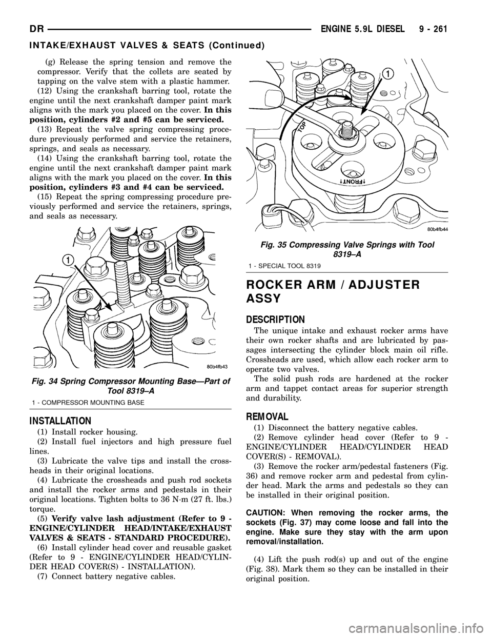
(a) Install the valve spring compressor mounting
base as shown in (Fig. 34).
(b) Install the top plate, washer, and nut. Using
a suitable wrench tighten the nut (clock-wise) (Fig.
35) to compress the valve springs and remove the
collets.
(c) Rotate the compressor nut counter-clockwise
to relieve tension on springs. Remove spring com-
pressor.
(d) Remove and replace retainers, springs, and
seals as necessary.
(e)Do not rotate the engine until the
springs and retainers are re-installed.
(f) Install seals, springs and retainers. Install
spring compressor, compress valve springs and
install the collets.
Fig. 32 Measuring Valve Lash - Typical
1 - INTAKE
2 - FEELER GAUGE
3 - EXHAUST
Fig. 33 Rotating Engine with Barring Tool - Typical
1 - REAR FLANGE
2 - BARRING TOOL
9 - 260 ENGINE 5.9L DIESELDR
INTAKE/EXHAUST VALVES & SEATS (Continued)
Page 1484 of 2627
(g) Release the spring tension and remove the
compressor. Verify that the collets are seated by
tapping on the valve stem with a plastic hammer.
(12) Using the crankshaft barring tool, rotate the
engine until the next crankshaft damper paint mark
aligns with the mark you placed on the cover.In this
position, cylinders #2 and #5 can be serviced.
(13) Repeat the valve spring compressing proce-
dure previously performed and service the retainers,
springs, and seals as necessary.
(14) Using the crankshaft barring tool, rotate the
engine until the next crankshaft damper paint mark
aligns with the mark you placed on the cover.In this
position, cylinders #3 and #4 can be serviced.
(15) Repeat the spring compressing procedure pre-
viously performed and service the retainers, springs,
and seals as necessary.
INSTALLATION
(1) Install rocker housing.
(2) Install fuel injectors and high pressure fuel
lines.
(3) Lubricate the valve tips and install the cross-
heads in their original locations.
(4) Lubricate the crossheads and push rod sockets
and install the rocker arms and pedestals in their
original locations. Tighten bolts to 36 N´m (27 ft. lbs.)
torque.
(5)Verify valve lash adjustment (Refer to 9 -
ENGINE/CYLINDER HEAD/INTAKE/EXHAUST
VALVES & SEATS - STANDARD PROCEDURE).
(6) Install cylinder head cover and reusable gasket
(Refer to 9 - ENGINE/CYLINDER HEAD/CYLIN-
DER HEAD COVER(S) - INSTALLATION).
(7) Connect battery negative cables.
ROCKER ARM / ADJUSTER
ASSY
DESCRIPTION
The unique intake and exhaust rocker arms have
their own rocker shafts and are lubricated by pas-
sages intersecting the cylinder block main oil rifle.
Crossheads are used, which allow each rocker arm to
operate two valves.
The solid push rods are hardened at the rocker
arm and tappet contact areas for superior strength
and durability.
REMOVAL
(1) Disconnect the battery negative cables.
(2) Remove cylinder head cover (Refer to 9 -
ENGINE/CYLINDER HEAD/CYLINDER HEAD
COVER(S) - REMOVAL).
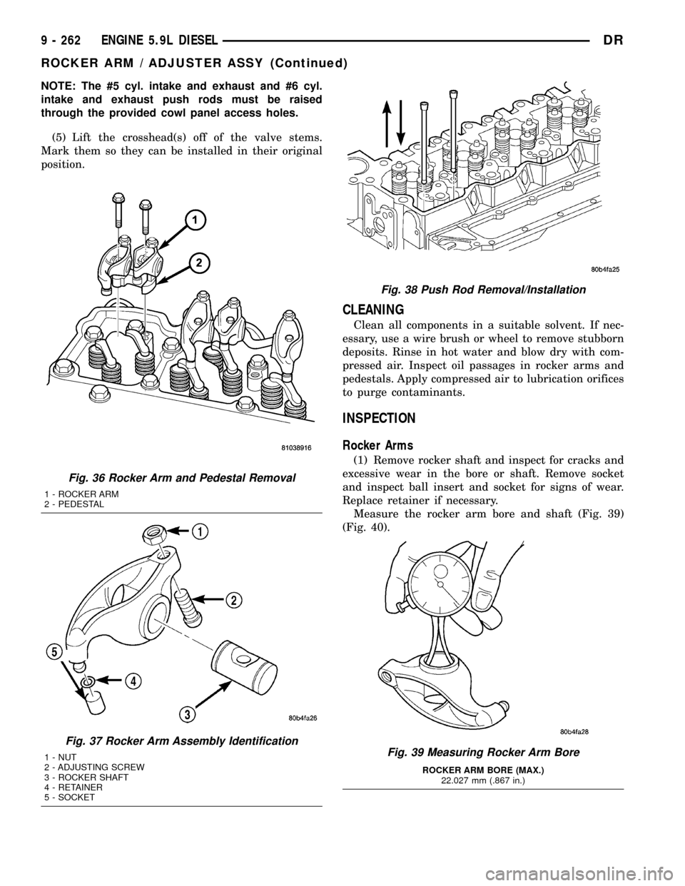
(3) Remove the rocker arm/pedestal fasteners (Fig.
36) and remove rocker arm and pedestal from cylin-
der head. Mark the arms and pedestals so they can
be installed in their original position.
CAUTION: When removing the rocker arms, the
sockets (Fig. 37) may come loose and fall into the
engine. Make sure they stay with the arm upon
removal/installation.
(4) Lift the push rod(s) up and out of the engine
(Fig. 38). Mark them so they can be installed in their
original position.
Fig. 34 Spring Compressor Mounting BaseÐPart of
Tool 8319±A
1 - COMPRESSOR MOUNTING BASE
Fig. 35 Compressing Valve Springs with Tool
8319±A
1 - SPECIAL TOOL 8319
DRENGINE 5.9L DIESEL 9 - 261
INTAKE/EXHAUST VALVES & SEATS (Continued)
Page 1485 of 2627
NOTE: The #5 cyl. intake and exhaust and #6 cyl.
intake and exhaust push rods must be raised
through the provided cowl panel access holes.
(5) Lift the crosshead(s) off of the valve stems.
Mark them so they can be installed in their original
position.
CLEANING
Clean all components in a suitable solvent. If nec-
essary, use a wire brush or wheel to remove stubborn
deposits. Rinse in hot water and blow dry with com-
pressed air. Inspect oil passages in rocker arms and
pedestals. Apply compressed air to lubrication orifices
to purge contaminants.
INSPECTION
Rocker Arms
(1) Remove rocker shaft and inspect for cracks and
excessive wear in the bore or shaft. Remove socket
and inspect ball insert and socket for signs of wear.
Replace retainer if necessary.
Measure the rocker arm bore and shaft (Fig. 39)
(Fig. 40).
Fig. 36 Rocker Arm and Pedestal Removal
1 - ROCKER ARM
2 - PEDESTAL
Fig. 37 Rocker Arm Assembly Identification
1 - NUT
2 - ADJUSTING SCREW
3 - ROCKER SHAFT
4 - RETAINER
5 - SOCKET
Fig. 38 Push Rod Removal/Installation
Fig. 39 Measuring Rocker Arm Bore
ROCKER ARM BORE (MAX.)
22.027 mm (.867 in.)
9 - 262 ENGINE 5.9L DIESELDR
ROCKER ARM / ADJUSTER ASSY (Continued)
Page 1486 of 2627
Push Rods
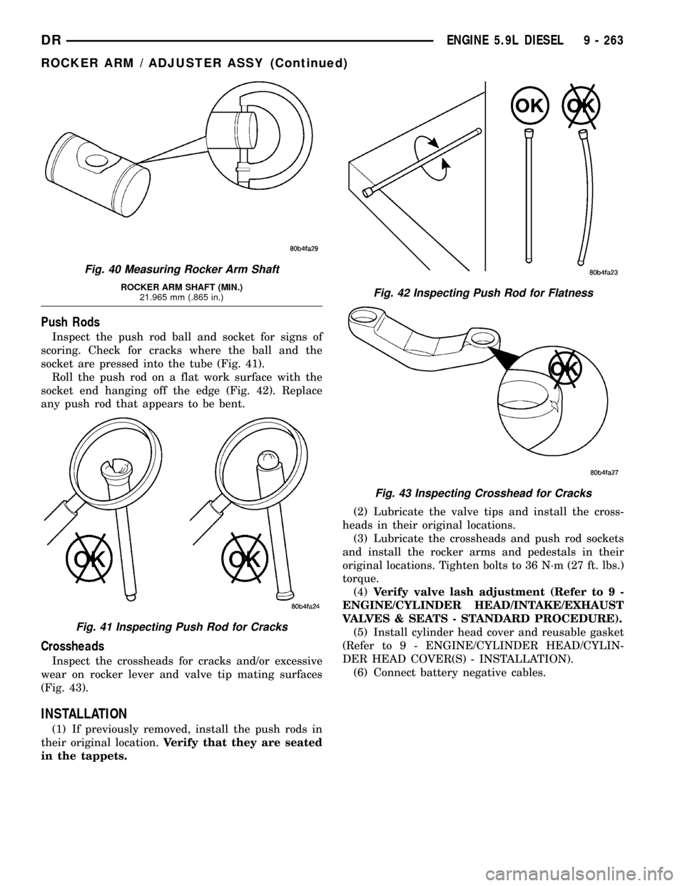
Inspect the push rod ball and socket for signs of
scoring. Check for cracks where the ball and the
socket are pressed into the tube (Fig. 41).
Roll the push rod on a flat work surface with the
socket end hanging off the edge (Fig. 42). Replace
any push rod that appears to be bent.
Crossheads
Inspect the crossheads for cracks and/or excessive
wear on rocker lever and valve tip mating surfaces
(Fig. 43).
INSTALLATION
(1) If previously removed, install the push rods in
their original location.Verify that they are seated
in the tappets.(2) Lubricate the valve tips and install the cross-
heads in their original locations.
(3) Lubricate the crossheads and push rod sockets
and install the rocker arms and pedestals in their
original locations. Tighten bolts to 36 N´m (27 ft. lbs.)
torque.
(4)Verify valve lash adjustment (Refer to 9 -
ENGINE/CYLINDER HEAD/INTAKE/EXHAUST
VALVES & SEATS - STANDARD PROCEDURE).
(5) Install cylinder head cover and reusable gasket
(Refer to 9 - ENGINE/CYLINDER HEAD/CYLIN-
DER HEAD COVER(S) - INSTALLATION).
(6) Connect battery negative cables.
Fig. 40 Measuring Rocker Arm Shaft
ROCKER ARM SHAFT (MIN.)
21.965 mm (.865 in.)
Fig. 41 Inspecting Push Rod for Cracks
Fig. 42 Inspecting Push Rod for Flatness
Fig. 43 Inspecting Crosshead for Cracks
DRENGINE 5.9L DIESEL 9 - 263
ROCKER ARM / ADJUSTER ASSY (Continued)