1998 DODGE RAM 1500 Rocker arms
[x] Cancel search: Rocker armsPage 1349 of 2627
base circle. Depress part of rocker arm over adjuster.
Normal adjusters should feel very firm. Spongy
adjusters can be bottomed out easily.
b. Remove suspected lash adjusters, and replace.
c. Before installation, make sure adjusters are at
least partially full of oil. This can be verified by little
or no plunger travel when lash adjuster is depressed.
REMOVAL
NOTE: Disconnect the battery negative cable to pre-
vent accidental starter engagement.
(1) Remove the cylinder head cover (Refer to 9 -
ENGINE/CYLINDER HEAD/CYLINDER HEAD
COVER(S) - REMOVAL).
(2) For rocker arm removal on cylinders 3 and 5
Rotate the crankshaft until cylinder #1 is at TDC
exhaust stroke.
(3) For rocker arm removal on cylinders 2 and 8
Rotate the crankshaft until cylinder #1 is at TDC
compression stroke.
(4) For rocker arm removal on cylinders 4 and 6
Rotate the crankshaft until cylinder #3 is at TDC
compression stroke.
(5) For rocker arm removal on cylinders 1 and 7
Rotate the crankshaft until cylinder #2 is at TDC
compression stroke.
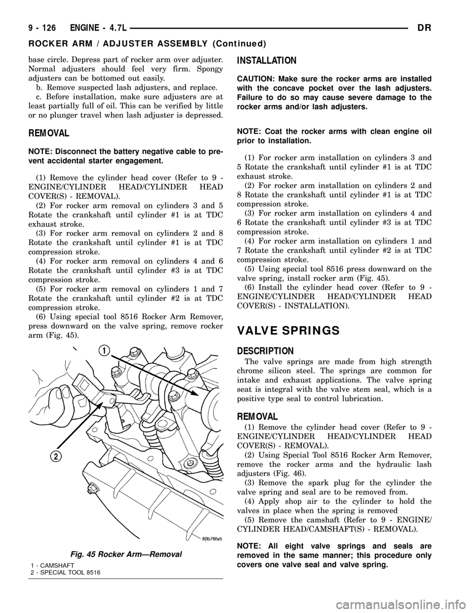
(6) Using special tool 8516 Rocker Arm Remover,
press downward on the valve spring, remove rocker
arm (Fig. 45).
INSTALLATION
CAUTION: Make sure the rocker arms are installed
with the concave pocket over the lash adjusters.
Failure to do so may cause severe damage to the
rocker arms and/or lash adjusters.
NOTE: Coat the rocker arms with clean engine oil
prior to installation.
(1) For rocker arm installation on cylinders 3 and
5 Rotate the crankshaft until cylinder #1 is at TDC
exhaust stroke.
(2) For rocker arm installation on cylinders 2 and
8 Rotate the crankshaft until cylinder #1 is at TDC
compression stroke.
(3) For rocker arm installation on cylinders 4 and
6 Rotate the crankshaft until cylinder #3 is at TDC
compression stroke.
(4) For rocker arm installation on cylinders 1 and
7 Rotate the crankshaft until cylinder #2 is at TDC
compression stroke.
(5) Using special tool 8516 press downward on the
valve spring, install rocker arm (Fig. 45).
(6) Install the cylinder head cover (Refer to 9 -
ENGINE/CYLINDER HEAD/CYLINDER HEAD
COVER(S) - INSTALLATION).
VALVE SPRINGS
DESCRIPTION
The valve springs are made from high strength
chrome silicon steel. The springs are common for
intake and exhaust applications. The valve spring
seat is integral with the valve stem seal, which is a
positive type seal to control lubrication.
REMOVAL
(1) Remove the cylinder head cover (Refer to 9 -
ENGINE/CYLINDER HEAD/CYLINDER HEAD
COVER(S) - REMOVAL).
(2) Using Special Tool 8516 Rocker Arm Remover,
remove the rocker arms and the hydraulic lash
adjusters (Fig. 46).
(3) Remove the spark plug for the cylinder the
valve spring and seal are to be removed from.
(4) Apply shop air to the cylinder to hold the
valves in place when the spring is removed
(5) Remove the camshaft (Refer to 9 - ENGINE/
CYLINDER HEAD/CAMSHAFT(S) - REMOVAL).
NOTE: All eight valve springs and seals are
removed in the same manner; this procedure only
covers one valve seal and valve spring.
Fig. 45 Rocker ArmÐRemoval
1 - CAMSHAFT
2 - SPECIAL TOOL 8516
9 - 126 ENGINE - 4.7LDR
ROCKER ARM / ADJUSTER ASSEMBLY (Continued)
Page 1350 of 2627
(6) Using Special Tool 8387 Valve Spring Compres-
sor, compress the valve spring.
NOTE: It may be necessary to tap the top of the
valve spring to loosen the spring retainers locks
enough to be removed.
(7) Remove the two spring retainer lock halves.
NOTE: the valve spring is under tension use care
when releasing the valve spring compressor.
(8) Remove the valve spring compressor.
(9) Remove the spring retainer, and the spring.
(10) Remove the valve stem seal.
NOTE: The valve stem seals are common between
intake and exhaust.
INSTALLATION
(1) coat the valve stem with clean engine oil and
install the valve stem seal. Make sure the seal is
fully seated and that the garter spring at the top of
the seal is intact.
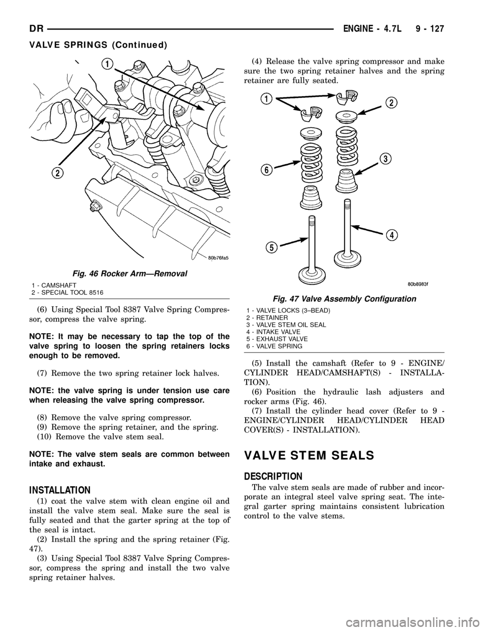
(2) Install the spring and the spring retainer (Fig.
47).
(3) Using Special Tool 8387 Valve Spring Compres-
sor, compress the spring and install the two valve
spring retainer halves.(4) Release the valve spring compressor and make
sure the two spring retainer halves and the spring
retainer are fully seated.
(5) Install the camshaft (Refer to 9 - ENGINE/
CYLINDER HEAD/CAMSHAFT(S) - INSTALLA-
TION).
(6) Position the hydraulic lash adjusters and
rocker arms (Fig. 46).
(7) Install the cylinder head cover (Refer to 9 -
ENGINE/CYLINDER HEAD/CYLINDER HEAD
COVER(S) - INSTALLATION).
VALVE STEM SEALS
DESCRIPTION
The valve stem seals are made of rubber and incor-
porate an integral steel valve spring seat. The inte-
gral garter spring maintains consistent lubrication
control to the valve stems.
Fig. 46 Rocker ArmÐRemoval
1 - CAMSHAFT
2 - SPECIAL TOOL 8516
Fig. 47 Valve Assembly Configuration
1 - VALVE LOCKS (3±BEAD)
2 - RETAINER
3 - VALVE STEM OIL SEAL
4 - INTAKE VALVE
5 - EXHAUST VALVE
6 - VALVE SPRING
DRENGINE - 4.7L 9 - 127
VALVE SPRINGS (Continued)
Page 1374 of 2627
The camshaft exhaust valve lobes and rocker arms
are lubricated through a small hole in the rocker
arm; oil flows through the lash adjuster then through
the rocker arm and onto the camshaft lobe. Due to
the orentation of the rocker arm, the camshaft intake
lobes are not lubed in the same manner as the
exhaust lobes. The intake lobes are lubed through
internal passages in the camshaft. Oil flows througha bore in the number 3 camshaft bearing bore, and
as the camshaft turns, a hole in the camshaft aligns
with the hole in the camshaft bore allowing engine
oil to enter the camshaft tube. The oil then exits
through 1.6mm (0.063 in.) holes drilled into the
intake lobes, lubricating the lobes and the rocker
arms.
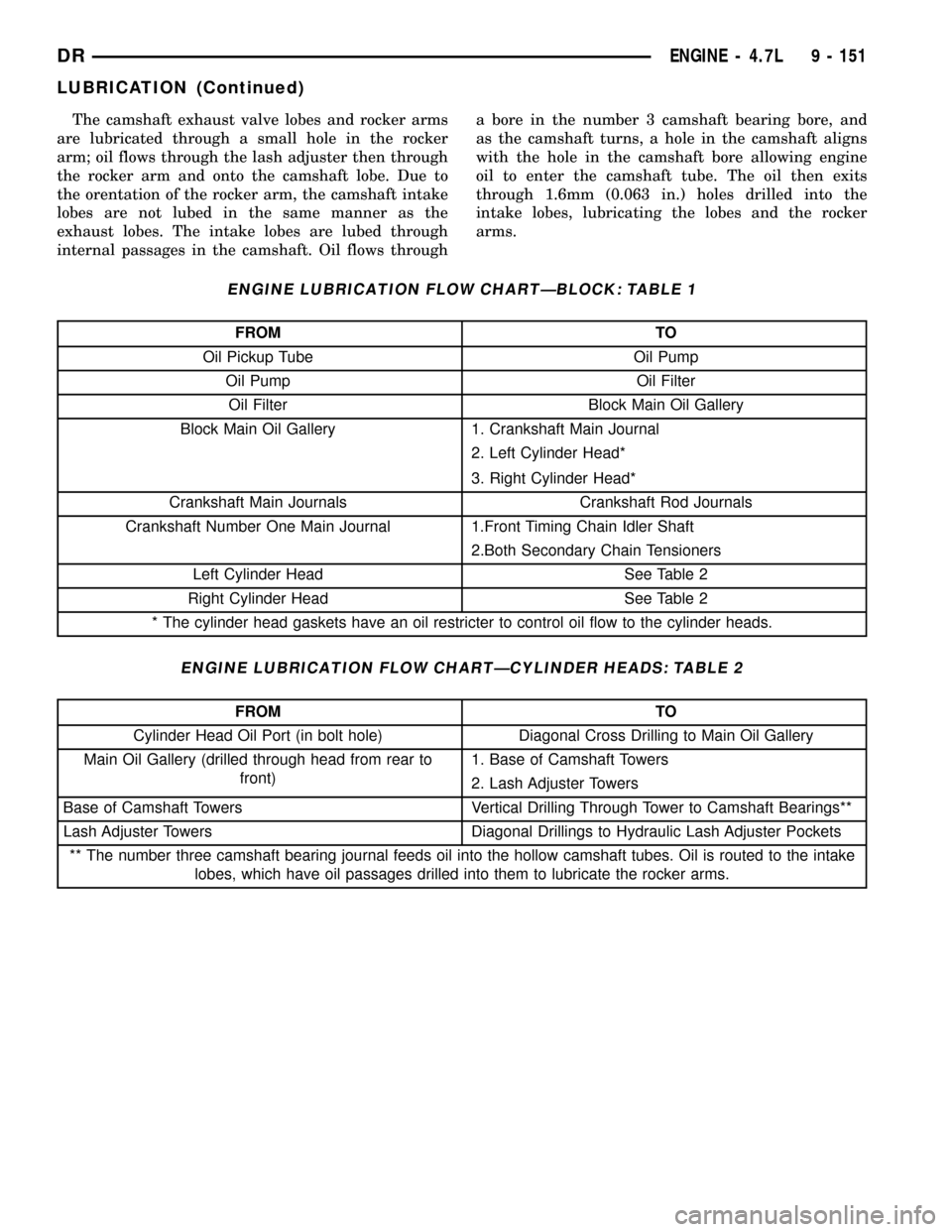
ENGINE LUBRICATION FLOW CHARTÐBLOCK: TABLE 1
FROM TO
Oil Pickup Tube Oil Pump
Oil Pump Oil Filter
Oil Filter Block Main Oil Gallery
Block Main Oil Gallery 1. Crankshaft Main Journal
2. Left Cylinder Head*
3. Right Cylinder Head*
Crankshaft Main Journals Crankshaft Rod Journals
Crankshaft Number One Main Journal 1.Front Timing Chain Idler Shaft
2.Both Secondary Chain Tensioners
Left Cylinder Head See Table 2
Right Cylinder Head See Table 2
* The cylinder head gaskets have an oil restricter to control oil flow to the cylinder heads.
ENGINE LUBRICATION FLOW CHARTÐCYLINDER HEADS: TABLE 2
FROM TO
Cylinder Head Oil Port (in bolt hole) Diagonal Cross Drilling to Main Oil Gallery
Main Oil Gallery (drilled through head from rear to
front)1. Base of Camshaft Towers
2. Lash Adjuster Towers
Base of Camshaft Towers Vertical Drilling Through Tower to Camshaft Bearings**
Lash Adjuster Towers Diagonal Drillings to Hydraulic Lash Adjuster Pockets
** The number three camshaft bearing journal feeds oil into the hollow camshaft tubes. Oil is routed to the intake
lobes, which have oil passages drilled into them to lubricate the rocker arms.
DRENGINE - 4.7L 9 - 151
LUBRICATION (Continued)
Page 1408 of 2627
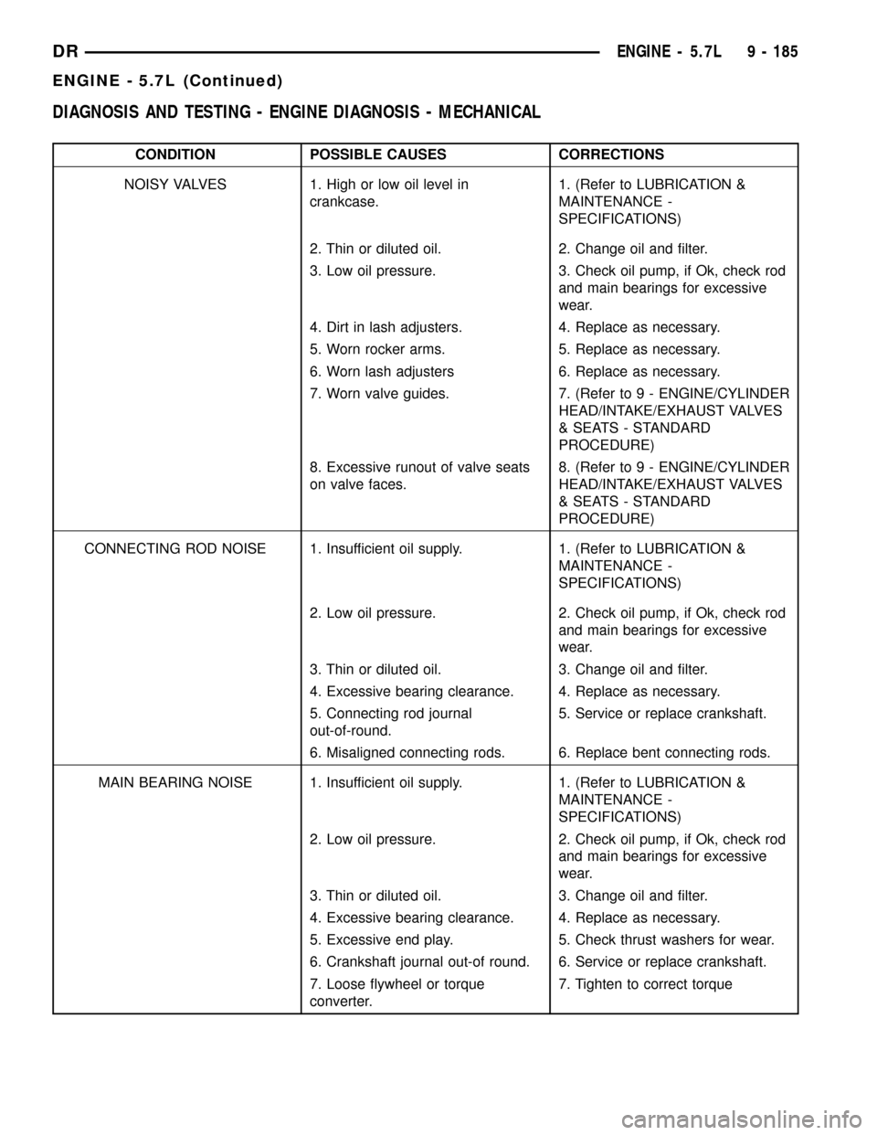
DIAGNOSIS AND TESTING - ENGINE DIAGNOSIS - MECHANICAL
CONDITION POSSIBLE CAUSES CORRECTIONS
NOISY VALVES 1. High or low oil level in
crankcase.1. (Refer to LUBRICATION &
MAINTENANCE -
SPECIFICATIONS)
2. Thin or diluted oil. 2. Change oil and filter.
3. Low oil pressure. 3. Check oil pump, if Ok, check rod
and main bearings for excessive
wear.
4. Dirt in lash adjusters. 4. Replace as necessary.
5. Worn rocker arms. 5. Replace as necessary.
6. Worn lash adjusters 6. Replace as necessary.
7. Worn valve guides. 7. (Refer to 9 - ENGINE/CYLINDER
HEAD/INTAKE/EXHAUST VALVES
& SEATS - STANDARD
PROCEDURE)
8. Excessive runout of valve seats
on valve faces.8. (Refer to 9 - ENGINE/CYLINDER
HEAD/INTAKE/EXHAUST VALVES
& SEATS - STANDARD
PROCEDURE)
CONNECTING ROD NOISE 1. Insufficient oil supply. 1. (Refer to LUBRICATION &
MAINTENANCE -
SPECIFICATIONS)
2. Low oil pressure. 2. Check oil pump, if Ok, check rod
and main bearings for excessive
wear.
3. Thin or diluted oil. 3. Change oil and filter.
4. Excessive bearing clearance. 4. Replace as necessary.
5. Connecting rod journal
out-of-round.5. Service or replace crankshaft.
6. Misaligned connecting rods. 6. Replace bent connecting rods.
MAIN BEARING NOISE 1. Insufficient oil supply. 1. (Refer to LUBRICATION &
MAINTENANCE -
SPECIFICATIONS)
2. Low oil pressure. 2. Check oil pump, if Ok, check rod
and main bearings for excessive
wear.
3. Thin or diluted oil. 3. Change oil and filter.
4. Excessive bearing clearance. 4. Replace as necessary.
5. Excessive end play. 5. Check thrust washers for wear.
6. Crankshaft journal out-of round. 6. Service or replace crankshaft.
7. Loose flywheel or torque
converter.7. Tighten to correct torque
DRENGINE - 5.7L 9 - 185
ENGINE - 5.7L (Continued)
Page 1411 of 2627
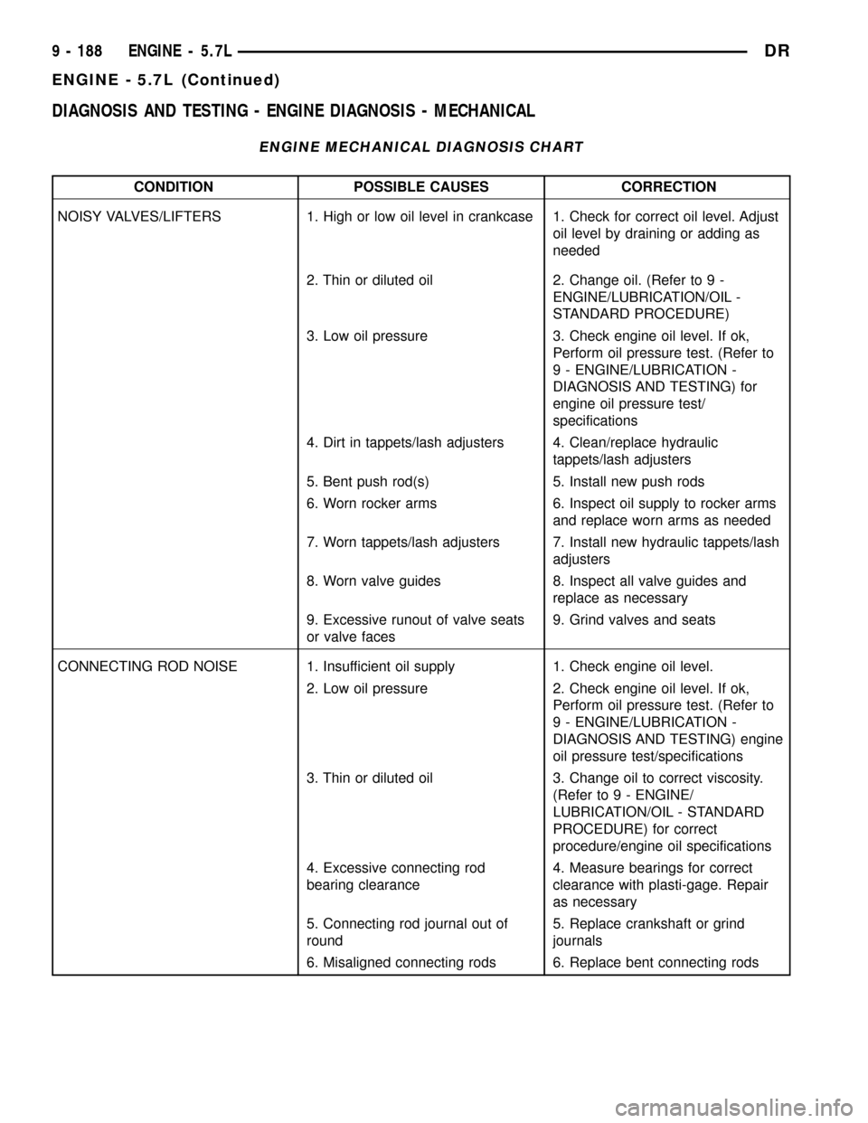
DIAGNOSIS AND TESTING - ENGINE DIAGNOSIS - MECHANICAL
ENGINE MECHANICAL DIAGNOSIS CHART
CONDITION POSSIBLE CAUSES CORRECTION
NOISY VALVES/LIFTERS 1. High or low oil level in crankcase 1. Check for correct oil level. Adjust
oil level by draining or adding as
needed
2. Thin or diluted oil 2. Change oil. (Refer to 9 -
ENGINE/LUBRICATION/OIL -
STANDARD PROCEDURE)
3. Low oil pressure 3. Check engine oil level. If ok,
Perform oil pressure test. (Refer to
9 - ENGINE/LUBRICATION -
DIAGNOSIS AND TESTING) for
engine oil pressure test/
specifications
4. Dirt in tappets/lash adjusters 4. Clean/replace hydraulic
tappets/lash adjusters
5. Bent push rod(s) 5. Install new push rods
6. Worn rocker arms 6. Inspect oil supply to rocker arms
and replace worn arms as needed
7. Worn tappets/lash adjusters 7. Install new hydraulic tappets/lash
adjusters
8. Worn valve guides 8. Inspect all valve guides and
replace as necessary
9. Excessive runout of valve seats
or valve faces9. Grind valves and seats
CONNECTING ROD NOISE 1. Insufficient oil supply 1. Check engine oil level.
2. Low oil pressure 2. Check engine oil level. If ok,
Perform oil pressure test. (Refer to
9 - ENGINE/LUBRICATION -
DIAGNOSIS AND TESTING) engine
oil pressure test/specifications
3. Thin or diluted oil 3. Change oil to correct viscosity.
(Refer to 9 - ENGINE/
LUBRICATION/OIL - STANDARD
PROCEDURE) for correct
procedure/engine oil specifications
4. Excessive connecting rod
bearing clearance4. Measure bearings for correct
clearance with plasti-gage. Repair
as necessary
5. Connecting rod journal out of
round5. Replace crankshaft or grind
journals
6. Misaligned connecting rods 6. Replace bent connecting rods
9 - 188 ENGINE - 5.7LDR
ENGINE - 5.7L (Continued)
Page 1426 of 2627
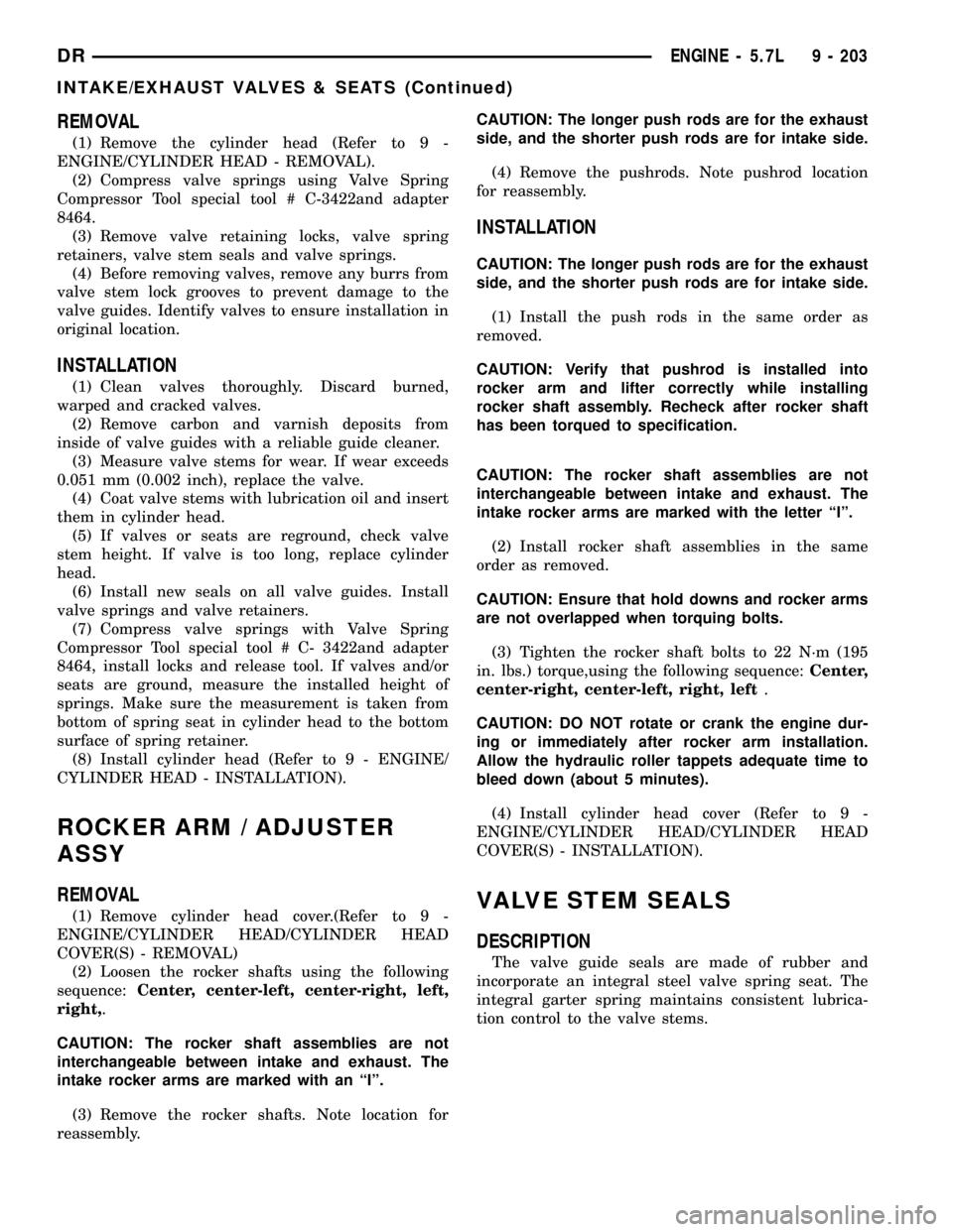
REMOVAL
(1) Remove the cylinder head (Refer to 9 -
ENGINE/CYLINDER HEAD - REMOVAL).
(2) Compress valve springs using Valve Spring
Compressor Tool special tool # C-3422and adapter
8464.
(3) Remove valve retaining locks, valve spring
retainers, valve stem seals and valve springs.
(4) Before removing valves, remove any burrs from
valve stem lock grooves to prevent damage to the
valve guides. Identify valves to ensure installation in
original location.
INSTALLATION
(1) Clean valves thoroughly. Discard burned,
warped and cracked valves.
(2) Remove carbon and varnish deposits from
inside of valve guides with a reliable guide cleaner.
(3) Measure valve stems for wear. If wear exceeds
0.051 mm (0.002 inch), replace the valve.
(4) Coat valve stems with lubrication oil and insert
them in cylinder head.
(5) If valves or seats are reground, check valve
stem height. If valve is too long, replace cylinder
head.
(6) Install new seals on all valve guides. Install
valve springs and valve retainers.
(7) Compress valve springs with Valve Spring
Compressor Tool special tool # C- 3422and adapter
8464, install locks and release tool. If valves and/or
seats are ground, measure the installed height of
springs. Make sure the measurement is taken from
bottom of spring seat in cylinder head to the bottom
surface of spring retainer.
(8) Install cylinder head (Refer to 9 - ENGINE/
CYLINDER HEAD - INSTALLATION).
ROCKER ARM / ADJUSTER
ASSY
REMOVAL
(1) Remove cylinder head cover.(Refer to 9 -
ENGINE/CYLINDER HEAD/CYLINDER HEAD
COVER(S) - REMOVAL)
(2) Loosen the rocker shafts using the following
sequence:Center, center-left, center-right, left,
right,.
CAUTION: The rocker shaft assemblies are not
interchangeable between intake and exhaust. The
intake rocker arms are marked with an ªIº.
(3) Remove the rocker shafts. Note location for
reassembly.CAUTION: The longer push rods are for the exhaust
side, and the shorter push rods are for intake side.
(4) Remove the pushrods. Note pushrod location
for reassembly.
INSTALLATION
CAUTION: The longer push rods are for the exhaust
side, and the shorter push rods are for intake side.
(1) Install the push rods in the same order as
removed.
CAUTION: Verify that pushrod is installed into
rocker arm and lifter correctly while installing
rocker shaft assembly. Recheck after rocker shaft
has been torqued to specification.
CAUTION: The rocker shaft assemblies are not
interchangeable between intake and exhaust. The
intake rocker arms are marked with the letter ªIº.
(2) Install rocker shaft assemblies in the same
order as removed.
CAUTION: Ensure that hold downs and rocker arms
are not overlapped when torquing bolts.
(3) Tighten the rocker shaft bolts to 22 N´m (195
in. lbs.) torque,using the following sequence:Center,
center-right, center-left, right, left.
CAUTION: DO NOT rotate or crank the engine dur-
ing or immediately after rocker arm installation.
Allow the hydraulic roller tappets adequate time to
bleed down (about 5 minutes).
(4) Install cylinder head cover (Refer to 9 -
ENGINE/CYLINDER HEAD/CYLINDER HEAD
COVER(S) - INSTALLATION).
VALVE STEM SEALS
DESCRIPTION
The valve guide seals are made of rubber and
incorporate an integral steel valve spring seat. The
integral garter spring maintains consistent lubrica-
tion control to the valve stems.
DRENGINE - 5.7L 9 - 203
INTAKE/EXHAUST VALVES & SEATS (Continued)
Page 1429 of 2627
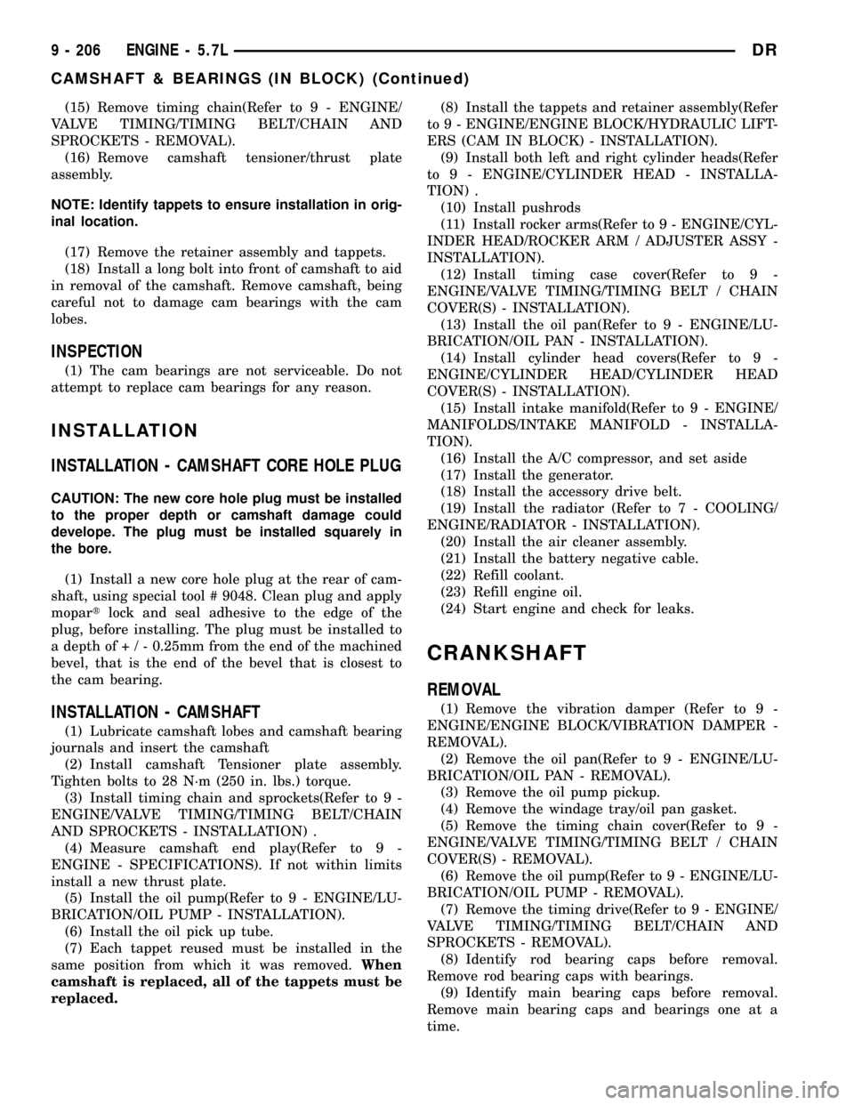
(15) Remove timing chain(Refer to 9 - ENGINE/
VALVE TIMING/TIMING BELT/CHAIN AND
SPROCKETS - REMOVAL).
(16) Remove camshaft tensioner/thrust plate
assembly.
NOTE: Identify tappets to ensure installation in orig-
inal location.
(17) Remove the retainer assembly and tappets.
(18) Install a long bolt into front of camshaft to aid
in removal of the camshaft. Remove camshaft, being
careful not to damage cam bearings with the cam
lobes.
INSPECTION
(1) The cam bearings are not serviceable. Do not
attempt to replace cam bearings for any reason.
INSTALLATION
INSTALLATION - CAMSHAFT CORE HOLE PLUG
CAUTION: The new core hole plug must be installed
to the proper depth or camshaft damage could
develope. The plug must be installed squarely in
the bore.
(1) Install a new core hole plug at the rear of cam-
shaft, using special tool # 9048. Clean plug and apply
mopartlock and seal adhesive to the edge of the
plug, before installing. The plug must be installed to
a depth of+/-0.25mm from the end of the machined
bevel, that is the end of the bevel that is closest to
the cam bearing.
INSTALLATION - CAMSHAFT
(1) Lubricate camshaft lobes and camshaft bearing
journals and insert the camshaft
(2) Install camshaft Tensioner plate assembly.
Tighten bolts to 28 N´m (250 in. lbs.) torque.
(3) Install timing chain and sprockets(Refer to 9 -
ENGINE/VALVE TIMING/TIMING BELT/CHAIN
AND SPROCKETS - INSTALLATION) .
(4) Measure camshaft end play(Refer to 9 -
ENGINE - SPECIFICATIONS). If not within limits
install a new thrust plate.
(5) Install the oil pump(Refer to 9 - ENGINE/LU-
BRICATION/OIL PUMP - INSTALLATION).
(6) Install the oil pick up tube.
(7) Each tappet reused must be installed in the
same position from which it was removed.When
camshaft is replaced, all of the tappets must be
replaced.(8) Install the tappets and retainer assembly(Refer
to 9 - ENGINE/ENGINE BLOCK/HYDRAULIC LIFT-
ERS (CAM IN BLOCK) - INSTALLATION).
(9) Install both left and right cylinder heads(Refer
to 9 - ENGINE/CYLINDER HEAD - INSTALLA-
TION) .
(10) Install pushrods
(11) Install rocker arms(Refer to 9 - ENGINE/CYL-
INDER HEAD/ROCKER ARM / ADJUSTER ASSY -
INSTALLATION).
(12) Install timing case cover(Refer to 9 -
ENGINE/VALVE TIMING/TIMING BELT / CHAIN
COVER(S) - INSTALLATION).
(13) Install the oil pan(Refer to 9 - ENGINE/LU-
BRICATION/OIL PAN - INSTALLATION).
(14) Install cylinder head covers(Refer to 9 -
ENGINE/CYLINDER HEAD/CYLINDER HEAD
COVER(S) - INSTALLATION).
(15) Install intake manifold(Refer to 9 - ENGINE/
MANIFOLDS/INTAKE MANIFOLD - INSTALLA-
TION).
(16) Install the A/C compressor, and set aside
(17) Install the generator.
(18) Install the accessory drive belt.
(19) Install the radiator (Refer to 7 - COOLING/
ENGINE/RADIATOR - INSTALLATION).
(20) Install the air cleaner assembly.
(21) Install the battery negative cable.
(22) Refill coolant.
(23) Refill engine oil.
(24) Start engine and check for leaks.
CRANKSHAFT
REMOVAL
(1) Remove the vibration damper (Refer to 9 -
ENGINE/ENGINE BLOCK/VIBRATION DAMPER -
REMOVAL).
(2) Remove the oil pan(Refer to 9 - ENGINE/LU-
BRICATION/OIL PAN - REMOVAL).
(3) Remove the oil pump pickup.
(4) Remove the windage tray/oil pan gasket.
(5) Remove the timing chain cover(Refer to 9 -
ENGINE/VALVE TIMING/TIMING BELT / CHAIN
COVER(S) - REMOVAL).
(6) Remove the oil pump(Refer to 9 - ENGINE/LU-
BRICATION/OIL PUMP - REMOVAL).
(7) Remove the timing drive(Refer to 9 - ENGINE/
VALVE TIMING/TIMING BELT/CHAIN AND
SPROCKETS - REMOVAL).
(8) Identify rod bearing caps before removal.
Remove rod bearing caps with bearings.
(9) Identify main bearing caps before removal.
Remove main bearing caps and bearings one at a
time.
9 - 206 ENGINE - 5.7LDR
CAMSHAFT & BEARINGS (IN BLOCK) (Continued)
Page 1458 of 2627
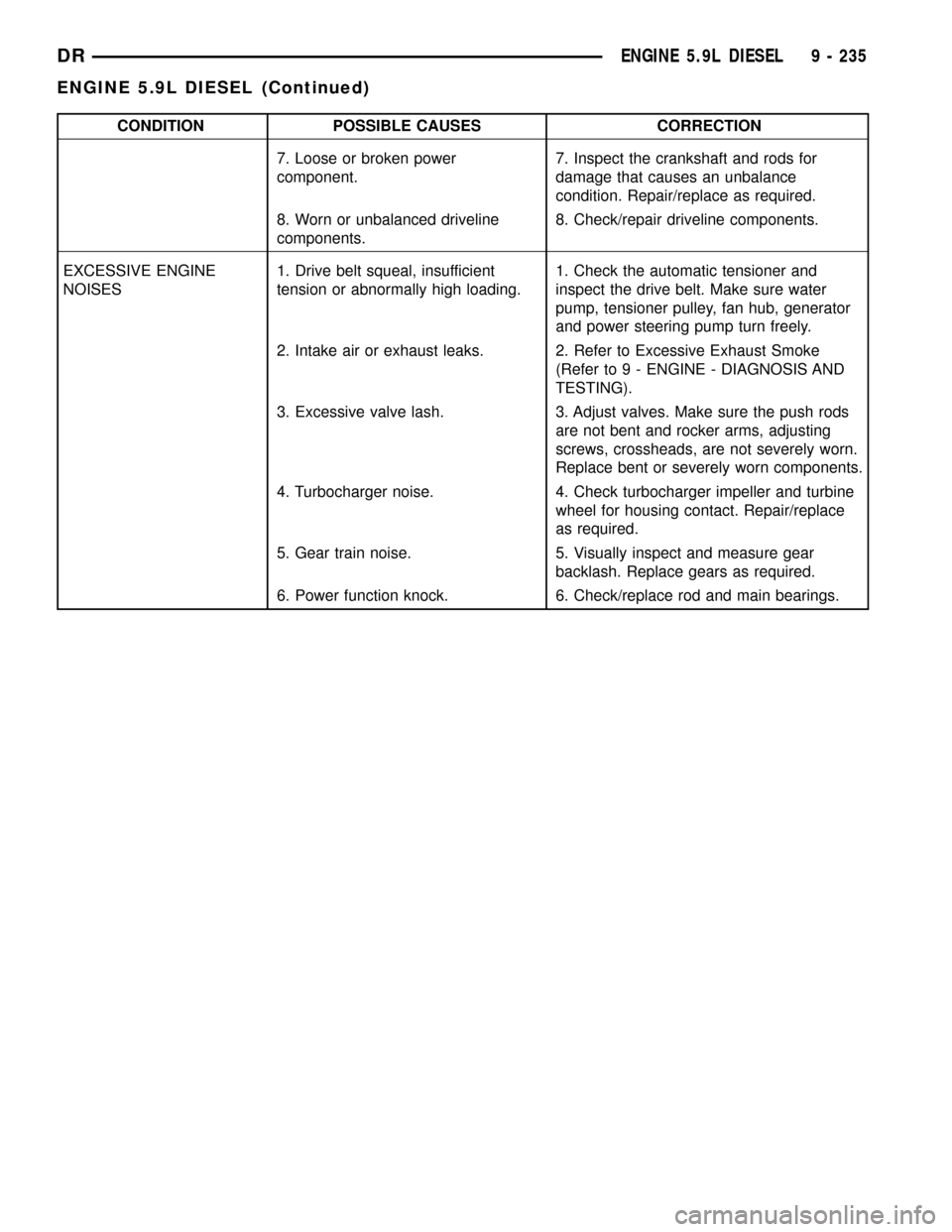
CONDITION POSSIBLE CAUSES CORRECTION
7. Loose or broken power
component.7. Inspect the crankshaft and rods for
damage that causes an unbalance
condition. Repair/replace as required.
8. Worn or unbalanced driveline
components.8. Check/repair driveline components.
EXCESSIVE ENGINE
NOISES1. Drive belt squeal, insufficient
tension or abnormally high loading.1. Check the automatic tensioner and
inspect the drive belt. Make sure water
pump, tensioner pulley, fan hub, generator
and power steering pump turn freely.
2. Intake air or exhaust leaks. 2. Refer to Excessive Exhaust Smoke
(Refer to 9 - ENGINE - DIAGNOSIS AND
TESTING).
3. Excessive valve lash. 3. Adjust valves. Make sure the push rods
are not bent and rocker arms, adjusting
screws, crossheads, are not severely worn.
Replace bent or severely worn components.
4. Turbocharger noise. 4. Check turbocharger impeller and turbine
wheel for housing contact. Repair/replace
as required.
5. Gear train noise. 5. Visually inspect and measure gear
backlash. Replace gears as required.
6. Power function knock. 6. Check/replace rod and main bearings.
DRENGINE 5.9L DIESEL 9 - 235
ENGINE 5.9L DIESEL (Continued)