1998 DODGE RAM 1500 Front axle
[x] Cancel search: Front axlePage 74 of 2627

SPRING
REMOVAL
(1) Raise and support the vehicle. Position a
hydraulic jack under the axle to support it.
(2) Paint or scribe alignment marks on lower sus-
pension arm cam adjusters and axle bracket for
installation reference.
(3) Remove the upper suspension arm and loosen
lower suspension arm bolts.
(4) Mark and disconnect the front propeller shaft
from the axle 4x4 models.
(5) Disconnect the track bar from the frame rail
bracket.
(6) Disconnect the drag link from pitman arm.
(7) Disconnect the stabilizer bar link and shock
absorber from the axle.
(8) Lower the axle until the spring is free from the
upper mount. Remove the coil spring.
INSTALLATION
(1) Position the coil spring on the axle pad.
(2) Raise the axle into position until the spring
seats in the upper mount.
(3) Connect the stabilizer bar links and shock
absorbers to the axle bracket. Connect the track bar
to the frame rail bracket.
(4) Install the upper suspension arm.
(5) Install the front propeller shaft to the axle 4x4
model.
(6) Install drag link to pitman arm and tighten
nut to specifications. Install new cotter pin.
(7) Remove the supports and lower the vehicle.
(8) Tighten the following suspension components
to specifications:
²Link to stabilizer bar nut.
²Lower shock bolt.
²Track bar bolt at axle shaft tube bracket.
²Upper suspension arm nut at axle bracket.
²Upper suspension nut at frame bracket.
²Align lower suspension arm reference marks and
tighten cam nut.
²Lower suspension nut at frame bracket.
STABILIZER BAR
REMOVAL
(1) Raise and support the vehicle.
(2) Hold the stabilizer link shafts with a wrench
and remove the link nuts at the stabilizer bar.
(3) Remove the retainers and grommets from the
stabilizer bar links.
(4) Remove the stabilizer bar link nuts from the
axle brackets.
Fig. 23 Shock Absorber and Bracket
1 - GROMMET
2 - RETAINER
3 - BRACKET
4 - RETAINER
5 - SHOCK
6 - GROMMET
Fig. 24 Shock Absorber Axle Mount
1 - SHOCK
2 - SPRING
3 - FLAG NUT
4 - SHOCK BOLT
DRFRONT - LINK/COIL 2 - 39
SHOCK (Continued)
Page 75 of 2627

(5) Remove the links from the axle brackets with
Puller C-3894-A (Fig. 25).
(6) Remove the stabilizer bar clamps from the
frame rails and remove the stabilizer bar.INSTALLATION
(1) Position the stabilizer bar on the frame rail
and install the clamps and bolts. Ensure the bar is
centered with equal spacing on both sides.
(2) Tighten the clamp bolts to 61 N´m (45 ft. lbs.).
(3) Install links to the axle bracket and tighten
nut to 71 N´m (52 ft. lbs.).
(4) Install links, retainers, grommets and nuts to
the stabilizer bar. Hold the link shaft with a wrench
and tighten the nuts to 37 N´m (27 ft. lbs.).
(5) Remove the supports and lower the vehicle.
Fig. 25 Stabilizer Link
1 - PULLER
2 - LINK
2 - 40 FRONT - LINK/COILDR
STABILIZER BAR (Continued)
Page 76 of 2627

REAR
TABLE OF CONTENTS
page page
REAR
DESCRIPTION.........................41
DIAGNOSIS AND TESTING - SPRING AND
SHOCK.............................41
SPECIFICATIONS
TORQUE CHART......................42
BUSHINGS
REMOVAL.............................43
INSTALLATION.........................43
JOUNCE BUMPER
REMOVAL.............................43
INSTALLATION.........................43
AUXILIARY SPRING BUMPERS (3500)
REMOVAL.............................43INSTALLATION.........................43
SHOCK
REMOVAL.............................43
INSTALLATION.........................43
SPRING
DESCRIPTION.........................44
OPERATION...........................44
REMOVAL.............................44
INSTALLATION.........................44
SPRING TIP INSERTS
REMOVAL.............................44
INSTALLATION.........................45
REAR
DESCRIPTION
The rear suspension is comprised of:
²Shock Absorbers
²Jounce Bumpers
²Leaf Springs
²Auxiliary Leaf Spring (3500 series)
²Auxiliary Spring Bumpers (3500 series)
²Drive Axle
CAUTION: A vehicle should always be loaded so
the vehicle weight center-line is located immedi-
ately forward of the rear axle. Correct vehicle load-
ing provides proper front tire-to-road contact. This
results in maximum vehicle handling stability and
safety. Incorrect vehicle weight distribution can
cause excessive tire tread wear, spring fatigue or
failure, and erratic steering.
CAUTION: Suspension components with rubber/ure-
thane bushings (except stabilizer bar) should be
tightened with the vehicle at normal ride height. It is
important to have the springs supporting the weight
of the vehicle when the fasteners are torqued. If
springs are not at their normal ride position, vehicle
ride comfort could be affected and premature bush-
ing wear may occur.
DIAGNOSIS AND TESTING - SPRING AND
SHOCK
A knocking or rattling noise from a shock absorber
may be caused by movement between mounting
bushings and metal brackets or attaching compo-
nents. These noises can usually be stopped by tight-
ening the attaching nuts. If the noise persists,
inspect for damaged and worn bushings, and attach-
ing components. Repair as necessary if any of these
conditions exist.
A squeaking noise from the shock absorber may be
caused by the hydraulic valving and may be intermit-
tent. This condition is not repairable and the shock
absorber must be replaced.
The shock absorbers are not refillable or adjust-
able. If a malfunction occurs, the shock absorber
must be replaced. To test a shock absorber, hold it in
an upright position and force the piston in and out of
the cylinder four or five times. The action throughout
each stroke should be smooth and even.
The spring eye and shock absorber bushings do not
require any type of lubrication. Do not attempt to
stop spring bushing noise by lubricating them.
Grease and mineral oil-base lubricants will deterio-
rate the bushing rubber.
If the vehicle is used for severe, off-road operation,
the springs should be examined periodically. Check
for broken and shifted leafs, loose and missing clips,
and broken center bolts. Refer to Spring and Shock
Absorber Diagnosis chart for additional information.
DRREAR 2 - 41
Page 79 of 2627

(3) Tighten the upper and lower bolt/nuts Tighten
to 135 N.m (100 ft. lbs.)
(4) Remove the support and lower the vehicle.
SPRING
DESCRIPTION
The rear suspension system uses a multi-leaf
springs and a solid drive axle. The forward end of the
springs are mounted to the body rail hangers
through rubber bushings. The rearward end of the
springs are attached to the body by the use of shack-
les. The spring and shackles use rubber bushings.
OPERATION
The springs control ride quality and maintain vehi-
cle ride height. The shackles allow the springs to
change their length as the vehicle moves over various
road conditions.
REMOVAL
(1) Raise and support the vehicle.
(2) Support the axle with a suitable holding fix-
ture.
(3) Remove the nuts, spring clamp bolts and the
plate that attach the spring to the axle (Fig. 4).
(4) Remove the nuts and bolts from the spring
front and rear shackle (Fig. 4).
(5) Remove the spring from the vehicle.
INSTALLATION
(1) Position spring on axle shaft tube so spring
center bolt is inserted into the locating hole in the
axle tube.(2) Align the front of the spring with the bolt hole
in the front bracket. Install the eye pivot bolt and
nut.
(3) Align the rear of the spring into the shackle
and install the bolt and nut.
(4) Tighten the spring front and rear eye pivot bolt
snug do not torque.
(5) Install the spring clamp bolts, plate and the
retaining nuts.
(6) Remove the holding fixture for the rear axle.
(7) Remove the supports and lower the vehicle so
that the weight is being supported by the tires.
(8) Tighten the spring clamp retaining nuts to 149
N´m (110 ft. lbs.).
(9) Tighten the spring front and rear pivot bolt
nuts to 163 N´m (120 ft. lbs.)(LD) or 230 N´m (170 ft.
lbs.)(HD).
SPRING TIP INSERTS
REMOVAL
(1) Raise and support the vehicle.
(2) Remove both rear tireand wheel assemblies
(3) Position a large C-Clamp adjacent to the spring
clinch clip and clamp the leaves of the spring
together
Fig. 3 SHOCK ABSORBER
1 - NUT
2 - AXLE
3 - SHOCK ABSORBER
Fig. 4 REAR SPRING
1 - LEAF SPRING
2 - PLATE
3 - NUTS
4 - FRONT NUT & BOLT
5 - SPRING CLAMP BOLTS
6 - SHACKLES
2 - 44 REARDR
SHOCK (Continued)
Page 82 of 2627

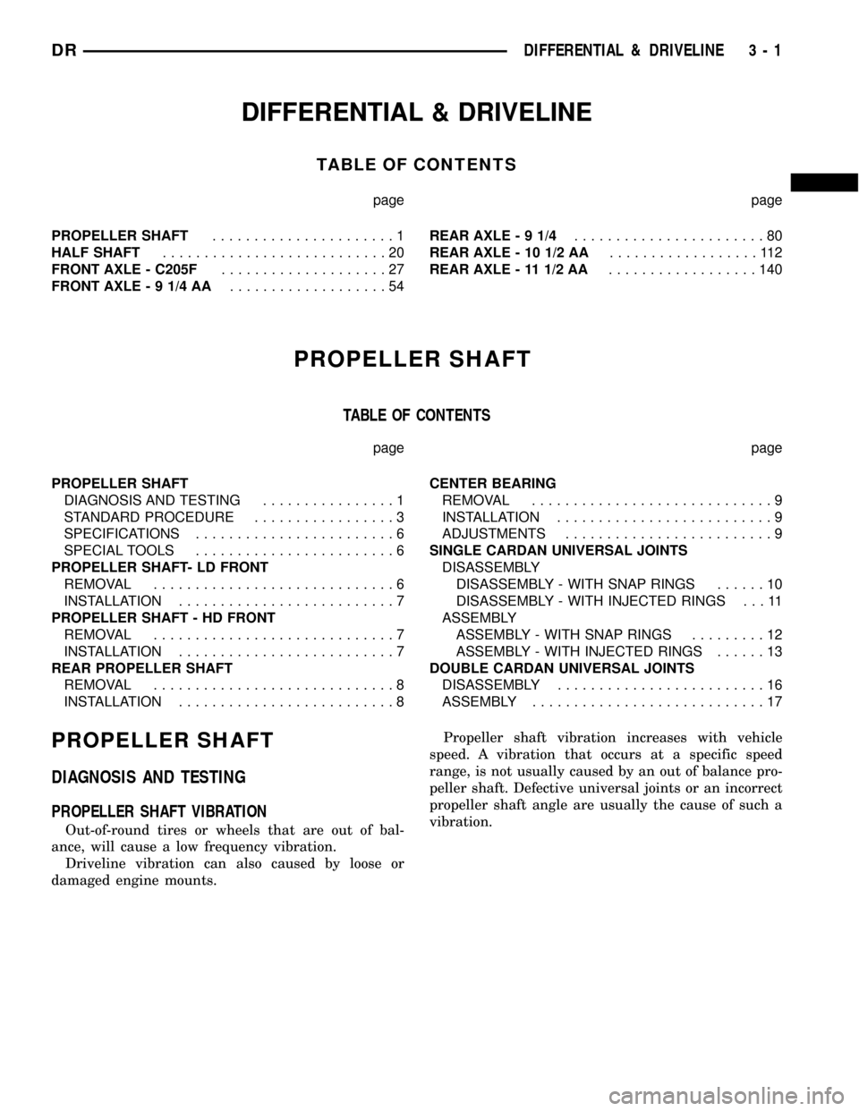
DIFFERENTIAL & DRIVELINE
TABLE OF CONTENTS
page page
PROPELLER SHAFT......................1
HALF SHAFT...........................20
FRONT AXLE - C205F....................27
FRONT AXLE - 9 1/4 AA...................54REAR AXLE-91/4.......................80
REAR AXLE - 10 1/2 AA..................112
REAR AXLE - 11 1/2 AA..................140
PROPELLER SHAFT
TABLE OF CONTENTS
page page
PROPELLER SHAFT
DIAGNOSIS AND TESTING................1
STANDARD PROCEDURE.................3
SPECIFICATIONS........................6
SPECIAL TOOLS........................6
PROPELLER SHAFT- LD FRONT
REMOVAL.............................6
INSTALLATION..........................7
PROPELLER SHAFT - HD FRONT
REMOVAL.............................7
INSTALLATION..........................7
REAR PROPELLER SHAFT
REMOVAL.............................8
INSTALLATION..........................8CENTER BEARING
REMOVAL.............................9
INSTALLATION..........................9
ADJUSTMENTS.........................9
SINGLE CARDAN UNIVERSAL JOINTS
DISASSEMBLY
DISASSEMBLY - WITH SNAP RINGS......10
DISASSEMBLY - WITH INJECTED RINGS . . . 11
ASSEMBLY
ASSEMBLY - WITH SNAP RINGS.........12
ASSEMBLY - WITH INJECTED RINGS......13
DOUBLE CARDAN UNIVERSAL JOINTS
DISASSEMBLY.........................16
ASSEMBLY............................17
PROPELLER SHAFT
DIAGNOSIS AND TESTING
PROPELLER SHAFT VIBRATION
Out-of-round tires or wheels that are out of bal-
ance, will cause a low frequency vibration.
Driveline vibration can also caused by loose or
damaged engine mounts.Propeller shaft vibration increases with vehicle
speed. A vibration that occurs at a specific speed
range, is not usually caused by an out of balance pro-
peller shaft. Defective universal joints or an incorrect
propeller shaft angle are usually the cause of such a
vibration.
DRDIFFERENTIAL & DRIVELINE 3 - 1
Page 84 of 2627

(10) Start engine and check vibration. If there is
little or no change move the clamp to the next posi-
tions. Repeat the vibration test.
NOTE: If there is no difference in vibration at this
positions, the vibration may not be the propeller
shaft.
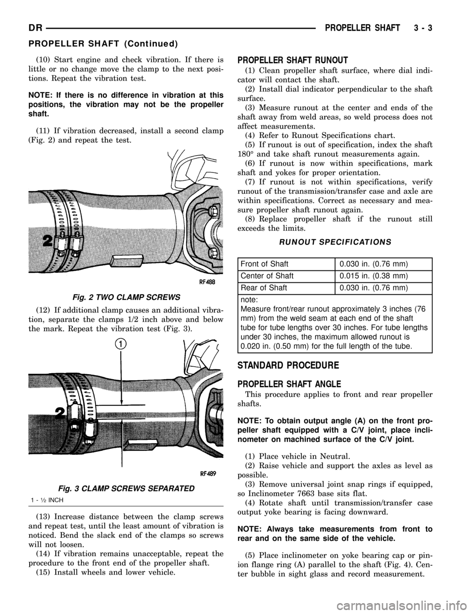
(11) If vibration decreased, install a second clamp
(Fig. 2) and repeat the test.
(12) If additional clamp causes an additional vibra-
tion, separate the clamps 1/2 inch above and below
the mark. Repeat the vibration test (Fig. 3).
(13) Increase distance between the clamp screws
and repeat test, until the least amount of vibration is
noticed. Bend the slack end of the clamps so screws
will not loosen.
(14) If vibration remains unacceptable, repeat the
procedure to the front end of the propeller shaft.
(15) Install wheels and lower vehicle.PROPELLER SHAFT RUNOUT
(1) Clean propeller shaft surface, where dial indi-
cator will contact the shaft.
(2) Install dial indicator perpendicular to the shaft
surface.
(3) Measure runout at the center and ends of the
shaft away from weld areas, so weld process does not
affect measurements.
(4) Refer to Runout Specifications chart.
(5) If runout is out of specification, index the shaft
180É and take shaft runout measurements again.
(6) If runout is now within specifications, mark
shaft and yokes for proper orientation.
(7) If runout is not within specifications, verify
runout of the transmission/transfer case and axle are
within specifications. Correct as necessary and mea-
sure propeller shaft runout again.
(8) Replace propeller shaft if the runout still
exceeds the limits.
RUNOUT SPECIFICATIONS
Front of Shaft 0.030 in. (0.76 mm)
Center of Shaft 0.015 in. (0.38 mm)
Rear of Shaft 0.030 in. (0.76 mm)
note:
Measure front/rear runout approximately 3 inches (76
mm) from the weld seam at each end of the shaft
tube for tube lengths over 30 inches. For tube lengths
under 30 inches, the maximum allowed runout is
0.020 in. (0.50 mm) for the full length of the tube.
STANDARD PROCEDURE
PROPELLER SHAFT ANGLE
This procedure applies to front and rear propeller
shafts.
NOTE: To obtain output angle (A) on the front pro-
peller shaft equipped with a C/V joint, place incli-
nometer on machined surface of the C/V joint.
(1) Place vehicle in Neutral.
(2) Raise vehicle and support the axles as level as
possible.
(3) Remove universal joint snap rings if equipped,
so Inclinometer 7663 base sits flat.
(4) Rotate shaft until transmission/transfer case
output yoke bearing is facing downward.
NOTE: Always take measurements from front to
rear and on the same side of the vehicle.
(5) Place inclinometer on yoke bearing cap or pin-
ion flange ring (A) parallel to the shaft (Fig. 4). Cen-
ter bubble in sight glass and record measurement.
Fig. 2 TWO CLAMP SCREWS
Fig. 3 CLAMP SCREWS SEPARATED
1-1¤2INCH
DRPROPELLER SHAFT 3 - 3
PROPELLER SHAFT (Continued)
Page 87 of 2627

SPECIFICATIONS
TORQUE SPECIFICATIONS
DESCRIPTION N´m Ft. Lbs. In. Lbs.
Center Bearing Bolts 54 40 -
Transfer Case Flange
Bolts88 65 -
LD - Front Pinion Flange
Bolts11 5 8 5 -
HD - Front Pinion Flange
Bolts28 21 -
Rear Pinion Flange Bolts 115 85 -
Rear Pinion Yoke Bolts 29 22 -
SPECIAL TOOLSPROPELLER SHAFT- LD
FRONT
REMOVAL
(1) With vehicle in neutral, position vehicle on
hoist.
(2) Remove exhaust crossover pipe.
(3) Mark a line across the axle companion flange,
propeller shaft flange yoke and transfer case (Fig. 9)
for installation reference.
INCLINOMETER 7663
Bearing Splitter 1130
INSTALLER 6052
Fig. 9 COMPANION FLANGE
1 - COMPANION FLANGE
2 - PROPELLER SHAFT
3 - FLANGE YOKE
4 - REFERENCE MARK
3 - 6 PROPELLER SHAFTDR
PROPELLER SHAFT (Continued)
Page 88 of 2627

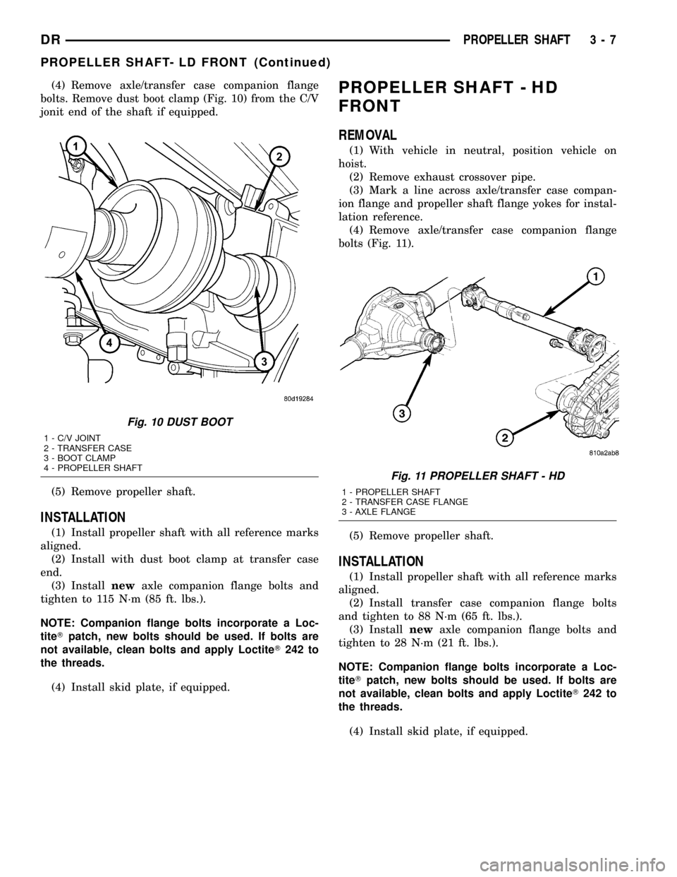
(4) Remove axle/transfer case companion flange
bolts. Remove dust boot clamp (Fig. 10) from the C/V
jonit end of the shaft if equipped.
(5) Remove propeller shaft.
INSTALLATION
(1) Install propeller shaft with all reference marks
aligned.
(2) Install with dust boot clamp at transfer case
end.
(3) Installnewaxle companion flange bolts and
tighten to 115 N´m (85 ft. lbs.).
NOTE: Companion flange bolts incorporate a Loc-
titeTpatch, new bolts should be used. If bolts are
not available, clean bolts and apply LoctiteT242 to
the threads.
(4) Install skid plate, if equipped.
PROPELLER SHAFT - HD
FRONT
REMOVAL
(1) With vehicle in neutral, position vehicle on
hoist.
(2) Remove exhaust crossover pipe.
(3) Mark a line across axle/transfer case compan-
ion flange and propeller shaft flange yokes for instal-
lation reference.
(4) Remove axle/transfer case companion flange
bolts (Fig. 11).
(5) Remove propeller shaft.
INSTALLATION
(1) Install propeller shaft with all reference marks
aligned.
(2) Install transfer case companion flange bolts
and tighten to 88 N´m (65 ft. lbs.).
(3) Installnewaxle companion flange bolts and
tighten to 28 N´m (21 ft. lbs.).
NOTE: Companion flange bolts incorporate a Loc-
titeTpatch, new bolts should be used. If bolts are
not available, clean bolts and apply LoctiteT242 to
the threads.
(4) Install skid plate, if equipped.
Fig. 10 DUST BOOT
1 - C/V JOINT
2 - TRANSFER CASE
3 - BOOT CLAMP
4 - PROPELLER SHAFT
Fig. 11 PROPELLER SHAFT - HD
1 - PROPELLER SHAFT
2 - TRANSFER CASE FLANGE
3 - AXLE FLANGE
DRPROPELLER SHAFT 3 - 7
PROPELLER SHAFT- LD FRONT (Continued)