1998 DODGE RAM 1500 belt
[x] Cancel search: beltPage 2364 of 2627
(3) Using a trim stick C-4755 or equivalent,
remove the center seat belt trim bezel, if equipped.
(4) On quad cab models, remove the left lower
c-pillar trim panel. (Refer to 23 - BODY/INTERIOR/
C-PILLAR TRIM - REMOVAL)
(5) On standard cab models, remove the left lower
b-pillar trim panel. (Refer to 23 - BODY/INTERIOR/
B-PILLAR LOWER TRIM - REMOVAL)
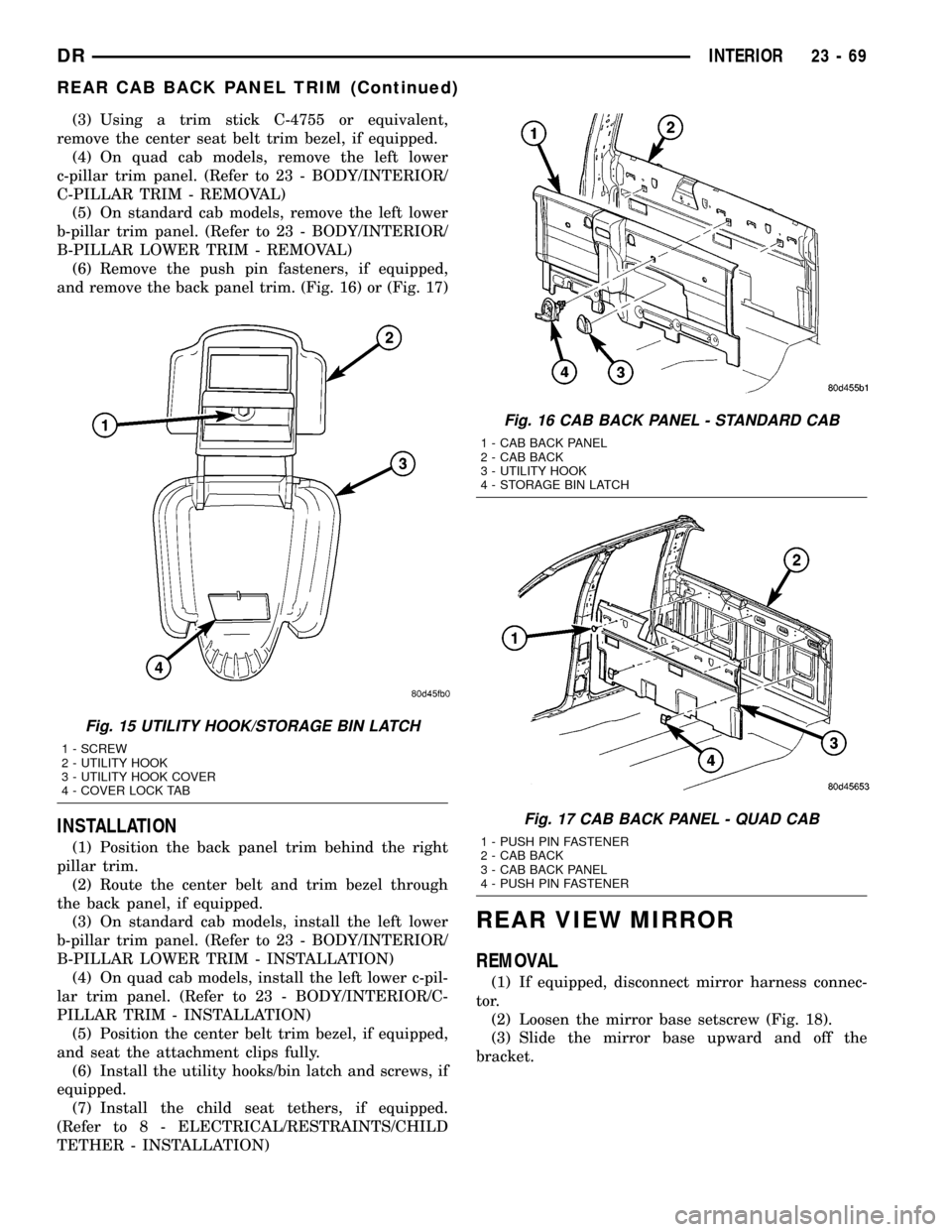
(6) Remove the push pin fasteners, if equipped,
and remove the back panel trim. (Fig. 16) or (Fig. 17)
INSTALLATION
(1) Position the back panel trim behind the right
pillar trim.
(2) Route the center belt and trim bezel through
the back panel, if equipped.
(3) On standard cab models, install the left lower
b-pillar trim panel. (Refer to 23 - BODY/INTERIOR/
B-PILLAR LOWER TRIM - INSTALLATION)
(4) On quad cab models, install the left lower c-pil-
lar trim panel. (Refer to 23 - BODY/INTERIOR/C-
PILLAR TRIM - INSTALLATION)
(5) Position the center belt trim bezel, if equipped,
and seat the attachment clips fully.
(6) Install the utility hooks/bin latch and screws, if
equipped.
(7) Install the child seat tethers, if equipped.
(Refer to 8 - ELECTRICAL/RESTRAINTS/CHILD
TETHER - INSTALLATION)
REAR VIEW MIRROR
REMOVAL
(1) If equipped, disconnect mirror harness connec-
tor.
(2) Loosen the mirror base setscrew (Fig. 18).
(3) Slide the mirror base upward and off the
bracket.
Fig. 15 UTILITY HOOK/STORAGE BIN LATCH
1 - SCREW
2 - UTILITY HOOK
3 - UTILITY HOOK COVER
4 - COVER LOCK TAB
Fig. 16 CAB BACK PANEL - STANDARD CAB
1 - CAB BACK PANEL
2 - CAB BACK
3 - UTILITY HOOK
4 - STORAGE BIN LATCH
Fig. 17 CAB BACK PANEL - QUAD CAB
1 - PUSH PIN FASTENER
2 - CAB BACK
3 - CAB BACK PANEL
4 - PUSH PIN FASTENER
DRINTERIOR 23 - 69
REAR CAB BACK PANEL TRIM (Continued)
Page 2386 of 2627
WEATHERSTRIP/SEALS
TABLE OF CONTENTS
page page
A-PILLAR WEATHERSTRIP RETAINER
REMOVAL.............................91
INSTALLATION.........................91
DRIP RAIL WEATHERSTRIP
REMOVAL.............................91
INSTALLATION.........................91
DOOR OPENING SEAL
REMOVAL.............................92
INSTALLATION.........................92
DRIP RAIL WEATHERSTRIP RETAINER
REMOVAL.............................92
INSTALLATION.........................92
FRONT DOOR GLASS RUN WEATHERSTRIP
REMOVAL.............................92
INSTALLATION.........................92FRONT DOOR OUTER BELT MOLDING
REMOVAL.............................92
INSTALLATION.........................93
FRONT DOOR INNER BELT MOLDING
REMOVAL.............................93
INSTALLATION.........................93
REAR DOOR GLASS RUN WEATHERSTRIP
REMOVAL.............................93
INSTALLATION.........................93
REAR DOOR OUTER BELT MOLDING
REMOVAL.............................93
INSTALLATION.........................94
REAR DOOR INNER BELT MOLDING
REMOVAL.............................94
INSTALLATION.........................94
A-PILLAR WEATHERSTRIP
RETAINER
REMOVAL
(1) Remove the drip rail weatherstrip retainer.
(Refer to 23 - BODY/WEATHERSTRIP/SEALS/DRIP
RAIL WEATHERSTRIP - REMOVAL)
(2) Remove the five screws and remove the weath-
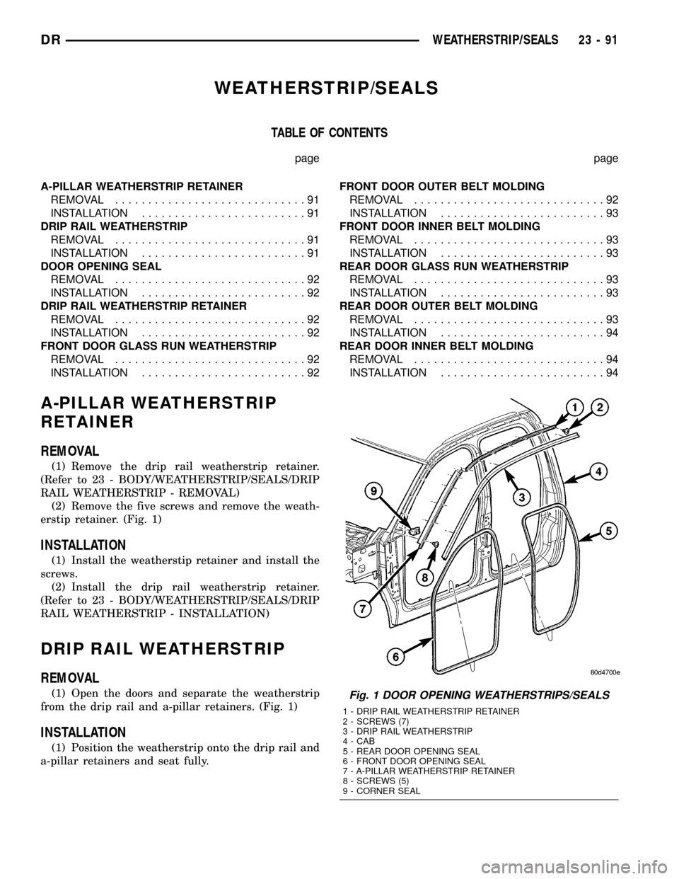
erstip retainer. (Fig. 1)
INSTALLATION
(1) Install the weatherstip retainer and install the
screws.
(2) Install the drip rail weatherstrip retainer.
(Refer to 23 - BODY/WEATHERSTRIP/SEALS/DRIP
RAIL WEATHERSTRIP - INSTALLATION)
DRIP RAIL WEATHERSTRIP
REMOVAL
(1) Open the doors and separate the weatherstrip
from the drip rail and a-pillar retainers. (Fig. 1)
INSTALLATION
(1) Position the weatherstrip onto the drip rail and
a-pillar retainers and seat fully.
Fig. 1 DOOR OPENING WEATHERSTRIPS/SEALS
1 - DRIP RAIL WEATHERSTRIP RETAINER
2 - SCREWS (7)
3 - DRIP RAIL WEATHERSTRIP
4 - CAB
5 - REAR DOOR OPENING SEAL
6 - FRONT DOOR OPENING SEAL
7 - A-PILLAR WEATHERSTRIP RETAINER
8 - SCREWS (5)
9 - CORNER SEAL
DRWEATHERSTRIP/SEALS 23 - 91
Page 2387 of 2627
DOOR OPENING SEAL
REMOVAL
FRONT DOOR SEAL
(1) Remove the cowl trim panel. (Refer to 23 -
BODY/INTERIOR/COWL TRIM - REMOVAL)
(2) Remove the lower b-pillar trim panel. (Refer to
23 - BODY/INTERIOR/B-PILLAR LOWER TRIM -
REMOVAL)
(3) Separate the door opening seal from the door
opening flange. (Fig. 1)
REAR DOOR SEAL
(1) Remove the lower b-pillar trim panel. (Refer to
23 - BODY/INTERIOR/B-PILLAR LOWER TRIM -
REMOVAL)
(2) Remove the lower c-pillar trim. (Refer to 23 -
BODY/INTERIOR/C-PILLAR TRIM - REMOVAL)
(3) Separate the door opening seal from the door
opening flange. (Fig. 1)
INSTALLATION
FRONT DOOR SEAL
(1) Position the seal to the bottom of the door
opening, with bulb facing outboard, starting the
installation at the center of the lower flange. Press
the seal onto the sill flange and work around the
perimeter of the door opening until fully seated.
Work in one direction, smoothing the seal to avoid
puckers or wrinkles.
(2) Install the lower b-pillar trim. (Refer to 23 -
BODY/INTERIOR/B-PILLAR LOWER TRIM -
INSTALLATION)
(3) Install the cowl trim panel. (Refer to 23 -
BODY/INTERIOR/COWL TRIM - INSTALLATION)
(4) When installing a new weatherstrip on the
front door opening, remove the tear strip starting at
the splice and moving around the front of the door to
the back of the opening.
REAR DOOR SEAL
(1) Position the seal to the bottom of the door
opening, with bulb facing outboard, starting the
installation at the center of the lower flange. Press
the seal onto the sill flange and work around the
perimeter of the door opening until fully seated.
Work in one direction, smoothing the seal to avoid
puckers or wrinkles.
(2) Install the lower c-pillar trim. (Refer to 23 -
BODY/INTERIOR/C-PILLAR TRIM - INSTALLA-
TION)
(3) Install the lower b-pillar trim. (Refer to 23 -
BODY/INTERIOR/B-PILLAR LOWER TRIM -
INSTALLATION)(4) When installing a new weatherstrip on the rear
door opening, remove the tear strip starting at the
splice and moving around the back of the door to the
front of the opening.
DRIP RAIL WEATHERSTRIP
RETAINER
REMOVAL
(1) Separate the drip rail weatherstrip from the
weatherstrip retainer. (Fig. 1)
(2) Remove the seven screws and remove the
retainer.
INSTALLATION
(1) Install the weatherstrip retainer and install
the seven screws.
(2) Position the weatherstrip over the retainer
flange and seat fully.
FRONT DOOR GLASS RUN
WEATHERSTRIP
REMOVAL
(1) Remove the door glass. (Refer to 23 - BODY/
DOOR - FRONT/DOOR GLASS - REMOVAL)
(2) Separate the weatherstrip out of the door
frame and remove through the window opening. (Fig.
2)
INSTALLATION
NOTE: A mixture of soap and water may be used to
aid installation of the weatherstrip into the corners.
(1) Position the glass run weatherstrip into the
door through the window opening.
(2) Position the weatherstrip into the upper cor-
ners and seat firmly.
(3) From back to front, seat the weatherstrip
between the corners and then down the sides firmly
(4) Install the door glass. (Refer to 23 - BODY/
DOOR - FRONT/DOOR GLASS - INSTALLATION)
FRONT DOOR OUTER BELT
MOLDING
REMOVAL
(1) Remove the screw and separate the belt mold-
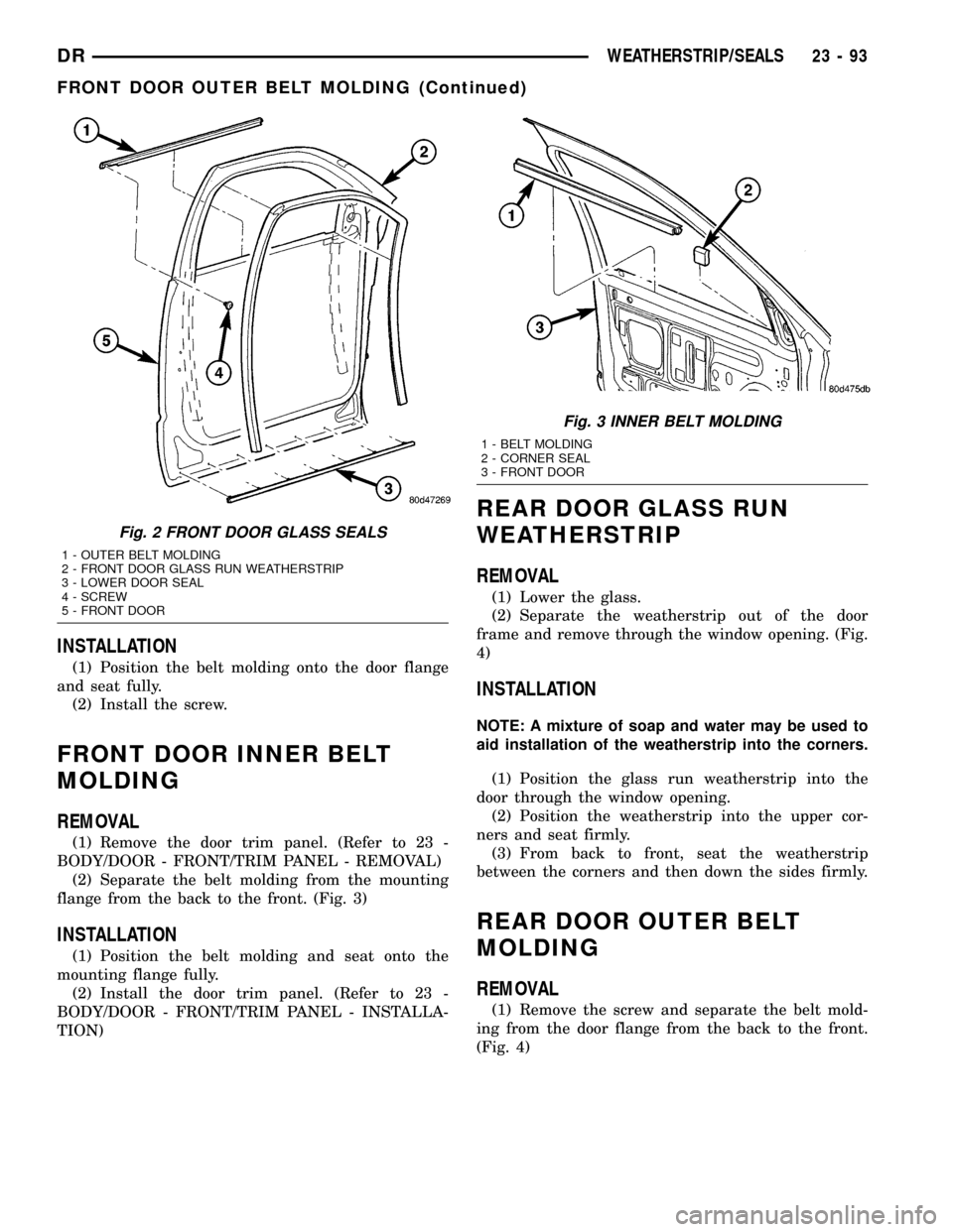
ing from the door flange from the back to the front.
(Fig. 2)
23 - 92 WEATHERSTRIP/SEALSDR
Page 2388 of 2627
INSTALLATION
(1) Position the belt molding onto the door flange
and seat fully.
(2) Install the screw.
FRONT DOOR INNER BELT
MOLDING
REMOVAL
(1) Remove the door trim panel. (Refer to 23 -
BODY/DOOR - FRONT/TRIM PANEL - REMOVAL)
(2) Separate the belt molding from the mounting
flange from the back to the front. (Fig. 3)
INSTALLATION
(1) Position the belt molding and seat onto the
mounting flange fully.
(2) Install the door trim panel. (Refer to 23 -
BODY/DOOR - FRONT/TRIM PANEL - INSTALLA-
TION)
REAR DOOR GLASS RUN
WEATHERSTRIP
REMOVAL
(1) Lower the glass.
(2) Separate the weatherstrip out of the door
frame and remove through the window opening. (Fig.
4)
INSTALLATION
NOTE: A mixture of soap and water may be used to
aid installation of the weatherstrip into the corners.
(1) Position the glass run weatherstrip into the
door through the window opening.
(2) Position the weatherstrip into the upper cor-
ners and seat firmly.
(3) From back to front, seat the weatherstrip
between the corners and then down the sides firmly.
REAR DOOR OUTER BELT
MOLDING
REMOVAL
(1) Remove the screw and separate the belt mold-
ing from the door flange from the back to the front.
(Fig. 4)
Fig. 2 FRONT DOOR GLASS SEALS
1 - OUTER BELT MOLDING
2 - FRONT DOOR GLASS RUN WEATHERSTRIP
3 - LOWER DOOR SEAL
4 - SCREW
5 - FRONT DOOR
Fig. 3 INNER BELT MOLDING
1 - BELT MOLDING
2 - CORNER SEAL
3 - FRONT DOOR
DRWEATHERSTRIP/SEALS 23 - 93
FRONT DOOR OUTER BELT MOLDING (Continued)
Page 2389 of 2627
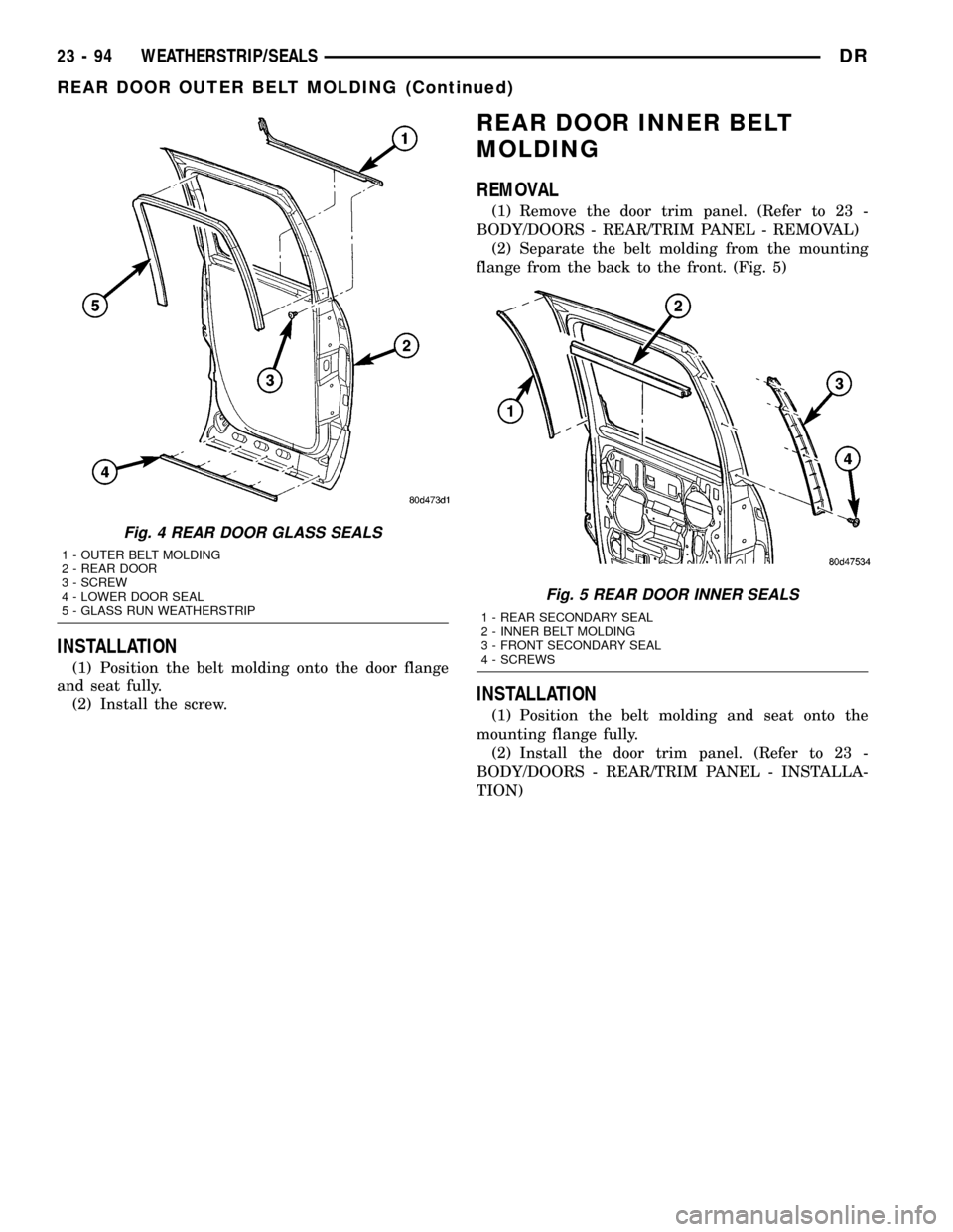
INSTALLATION
(1) Position the belt molding onto the door flange
and seat fully.
(2) Install the screw.
REAR DOOR INNER BELT
MOLDING
REMOVAL
(1) Remove the door trim panel. (Refer to 23 -
BODY/DOORS - REAR/TRIM PANEL - REMOVAL)
(2) Separate the belt molding from the mounting
flange from the back to the front. (Fig. 5)
INSTALLATION
(1) Position the belt molding and seat onto the
mounting flange fully.
(2) Install the door trim panel. (Refer to 23 -
BODY/DOORS - REAR/TRIM PANEL - INSTALLA-
TION)
Fig. 4 REAR DOOR GLASS SEALS
1 - OUTER BELT MOLDING
2 - REAR DOOR
3 - SCREW
4 - LOWER DOOR SEAL
5 - GLASS RUN WEATHERSTRIP
Fig. 5 REAR DOOR INNER SEALS
1 - REAR SECONDARY SEAL
2 - INNER BELT MOLDING
3 - FRONT SECONDARY SEAL
4 - SCREWS
23 - 94 WEATHERSTRIP/SEALSDR
REAR DOOR OUTER BELT MOLDING (Continued)
Page 2416 of 2627
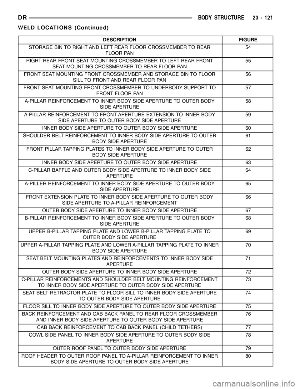
DESCRIPTION FIGURE
STORAGE BIN TO RIGHT AND LEFT REAR FLOOR CROSSMEMBER TO REAR
FLOOR PAN54
RIGHT REAR FRONT SEAT MOUNTING CROSSMEMBER TO LEFT REAR FRONT
SEAT MOUNTING CROSSMEMBER TO REAR FLOOR PAN55
FRONT SEAT MOUNTING FRONT CROSSMEMBER AND STORAGE BIN TO FLOOR
SILL TO FRONT AND REAR FLOOR PAN56
FRONT SEAT MOUNTING FRONT CROSSMEMBER TO UNDERBODY SUPPORT TO
FRONT FLOOR PAN57
A-PILLAR REINFORCEMENT TO INNER BODY SIDE APERTURE TO OUTER BODY
SIDE APERTURE58
A-PILLAR REINFORCEMENT TO FRONT APERTURE EXTENSION TO INNER BODY
SIDE APERTURE TO OUTER BODY SIDE APERTURE59
INNER BODY SIDE APERTURE TO OUTER BODY SIDE APERTURE 60
SHOULDER BELT REINFORCEMENT TO INNER BODY SIDE APERTURE TO OUTER
BODY SIDE APERTURE61
FRONT PILLAR TAPPING PLATES TO INNER BODY SIDE APERTURE TO OUTER
BODY SIDE APERTURE62
INNER BODY SIDE APERTURE TO OUTER BODY SIDE APERTURE 63
C-PILLAR BAFFLE AND OUTER BODY SIDE APERTURE TO INNER BODY SIDE
APERTURE64
A-PILLER REINFORCEMENT TO INNER BODY SIDE APERTURE TO OUTER BODY
SIDE APERTURE65
FRONT EXTENSION PLATE TO INNER BODY SIDE APERTURE TO OUTER BODY
SIDE APERTURE TO A-PILLAR REINFORCEMENT66
OUTER BODY SIDE APERTURE TO INNER BODY SIDE APERTURE 67
B-PILLAR REINFORCEMENT TO INNER BODY SIDE APERTURE TO OUTER BODY
SIDE APERTURE68
UPPER B-PILLAR TAPPING PLATE AND LOWER B-PILLAR TAPPING PLATE TO
OUTER BODY SIDE APERTURE69
UPPER A-PILLAR TAPPING PLATE AND LOWER A-PILLAR TAPPING PLATE TO INNER
BODY SIDE APERTURE70
SEAT BELT MOUNTING PLATES AND REINFORCEMENTS TO INNER BODY SIDE
APERTURE71
OUTER BODY SIDE APERTURE TO INNER BODY SIDE APERTURE 72
C-PILLAR REINFORCEMENTS AND SHOULDER BELT MOUNTING REINFORCEMENT
TO INNER BODY SIDE APERTURE TO OUTER BODY SIDE APERTURE73
SEAT BELT RETRACTOR PLATE TO FLOOR SILL TO INNER BODY SIDE APERTURE
TO OUTER BODY SIDE APERTURE74
FLOOR SILL TO INNER BODY SIDE APERTURE TO OUTER BODY SIDE APERTURE 75
BACK REINFORCEMENT AND CAB BACK PANEL TO REAR FLOOR CROSSMEMBER
AND INNER BODY SIDE APERTURE TO OUTER BODY SIDE APERTURE76
CAB BACK REINFORCEMENT TO CAB BACK PANEL (CHILD TETHERS) 77
COWL SIDE PANEL TO INNER BODY SIDE APERTURE TO OUTER BODY SIDE
APERTURE78
OUTER ROOF PANEL TO OUTER BODY SIDE APERTURE 79
ROOF HEADER TO OUTER ROOF PANEL TO A-PILLAR REINFORCEMENT TO INNER
BODY SIDE APERTURE TO OUTER BODY SIDE APERTURE80
DRBODY STRUCTURE 23 - 121
WELD LOCATIONS (Continued)
Page 2417 of 2627
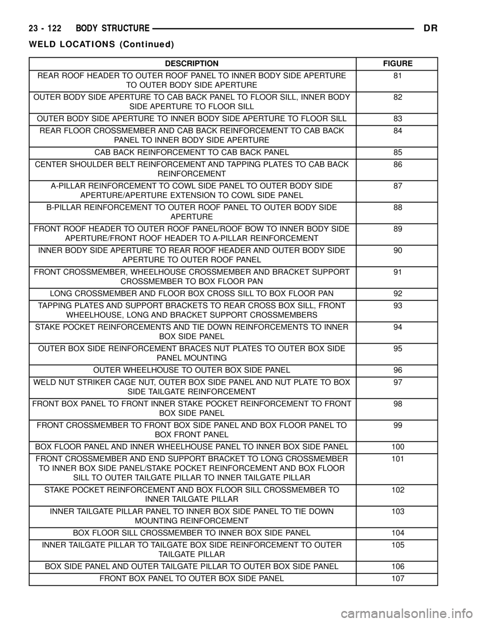
DESCRIPTION FIGURE
REAR ROOF HEADER TO OUTER ROOF PANEL TO INNER BODY SIDE APERTURE
TO OUTER BODY SIDE APERTURE81
OUTER BODY SIDE APERTURE TO CAB BACK PANEL TO FLOOR SILL, INNER BODY
SIDE APERTURE TO FLOOR SILL82
OUTER BODY SIDE APERTURE TO INNER BODY SIDE APERTURE TO FLOOR SILL 83
REAR FLOOR CROSSMEMBER AND CAB BACK REINFORCEMENT TO CAB BACK
PANEL TO INNER BODY SIDE APERTURE84
CAB BACK REINFORCEMENT TO CAB BACK PANEL 85
CENTER SHOULDER BELT REINFORCEMENT AND TAPPING PLATES TO CAB BACK
REINFORCEMENT86
A-PILLAR REINFORCEMENT TO COWL SIDE PANEL TO OUTER BODY SIDE
APERTURE/APERTURE EXTENSION TO COWL SIDE PANEL87
B-PILLAR REINFORCEMENT TO OUTER ROOF PANEL TO OUTER BODY SIDE
APERTURE88
FRONT ROOF HEADER TO OUTER ROOF PANEL/ROOF BOW TO INNER BODY SIDE
APERTURE/FRONT ROOF HEADER TO A-PILLAR REINFORCEMENT89
INNER BODY SIDE APERTURE TO REAR ROOF HEADER AND OUTER BODY SIDE
APERTURE TO OUTER ROOF PANEL90
FRONT CROSSMEMBER, WHEELHOUSE CROSSMEMBER AND BRACKET SUPPORT
CROSSMEMBER TO BOX FLOOR PAN91
LONG CROSSMEMBER AND FLOOR BOX CROSS SILL TO BOX FLOOR PAN 92
TAPPING PLATES AND SUPPORT BRACKETS TO REAR CROSS BOX SILL, FRONT
WHEELHOUSE, LONG AND BRACKET SUPPORT CROSSMEMBERS93
STAKE POCKET REINFORCEMENTS AND TIE DOWN REINFORCEMENTS TO INNER
BOX SIDE PANEL94
OUTER BOX SIDE REINFORCEMENT BRACES NUT PLATES TO OUTER BOX SIDE
PANEL MOUNTING95
OUTER WHEELHOUSE TO OUTER BOX SIDE PANEL 96
WELD NUT STRIKER CAGE NUT, OUTER BOX SIDE PANEL AND NUT PLATE TO BOX
SIDE TAILGATE REINFORCEMENT97
FRONT BOX PANEL TO FRONT INNER STAKE POCKET REINFORCEMENT TO FRONT
BOX SIDE PANEL98
FRONT CROSSMEMBER TO FRONT BOX SIDE PANEL AND BOX FLOOR PANEL TO
BOX FRONT PANEL99
BOX FLOOR PANEL AND INNER WHEELHOUSE PANEL TO INNER BOX SIDE PANEL 100
FRONT CROSSMEMBER AND END SUPPORT BRACKET TO LONG CROSSMEMBER
TO INNER BOX SIDE PANEL/STAKE POCKET REINFORCEMENT AND BOX FLOOR
SILL TO OUTER TAILGATE PILLAR TO INNER TAILGATE PILLAR101
STAKE POCKET REINFORCEMENT AND BOX FLOOR SILL CROSSMEMBER TO
INNER TAILGATE PILLAR102
INNER TAILGATE PILLAR PANEL TO INNER BOX SIDE PANEL TO TIE DOWN
MOUNTING REINFORCEMENT103
BOX FLOOR SILL CROSSMEMBER TO INNER BOX SIDE PANEL 104
INNER TAILGATE PILLAR TO TAILGATE BOX SIDE REINFORCEMENT TO OUTER
TAILGATE PILLAR105
BOX SIDE PANEL AND OUTER TAILGATE PILLAR TO OUTER BOX SIDE PANEL 106
FRONT BOX PANEL TO OUTER BOX SIDE PANEL 107
23 - 122 BODY STRUCTUREDR
WELD LOCATIONS (Continued)
Page 2442 of 2627
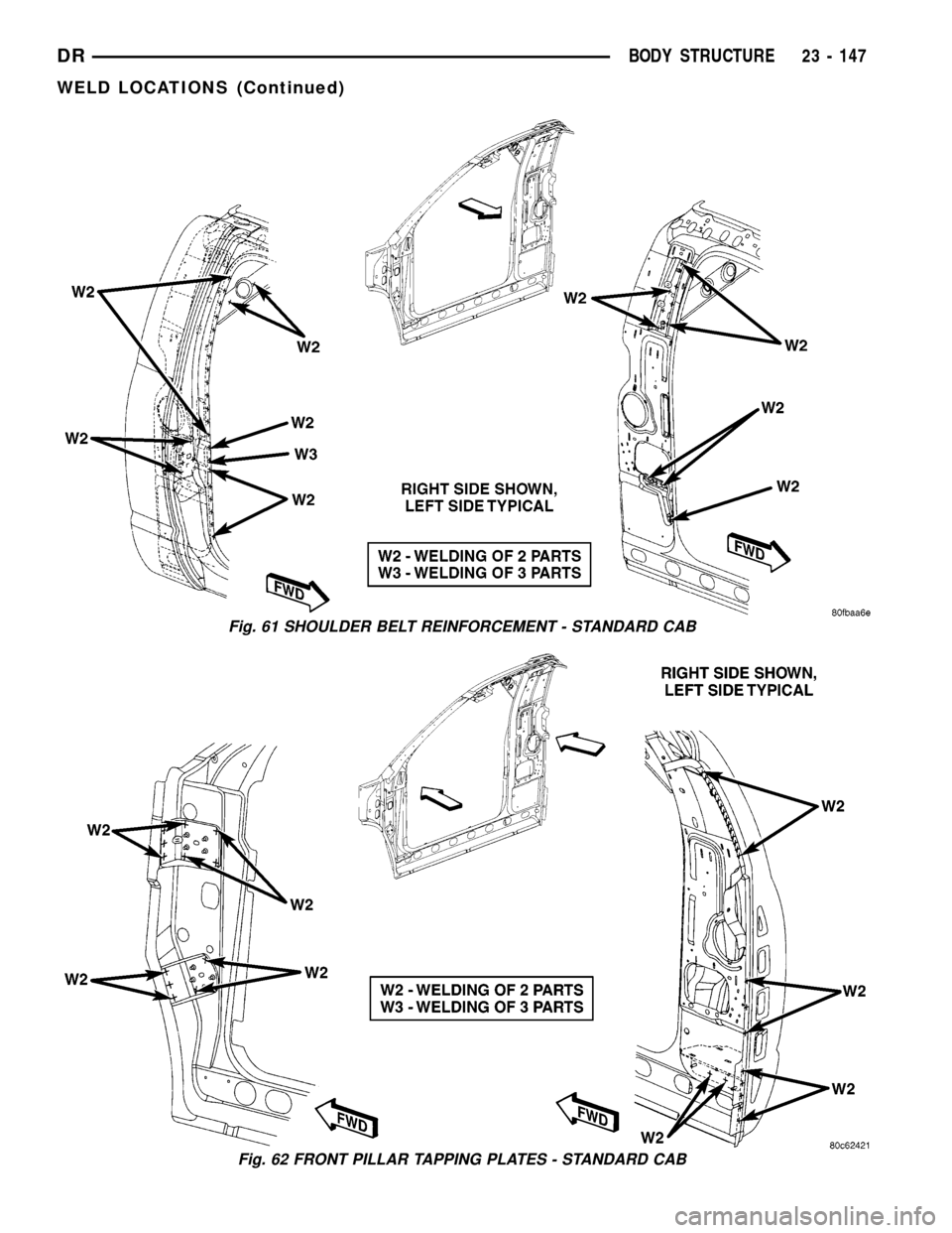
Fig. 61 SHOULDER BELT REINFORCEMENT - STANDARD CAB
Fig. 62 FRONT PILLAR TAPPING PLATES - STANDARD CAB
DRBODY STRUCTURE 23 - 147
WELD LOCATIONS (Continued)