1998 DODGE RAM 1500 belt
[x] Cancel search: beltPage 1623 of 2627

REMOVAL
CAUTION: Cleanliness cannot be overemphasized
when handling or replacing diesel fuel system com-
ponents. This especially includes the fuel injectors,
high-pressure fuel lines and fuel injection pump.
Very tight tolerances are used with these parts. Dirt
contamination could cause rapid part wear and pos-
sible plugging of fuel injector nozzle tip holes. This
in turn could lead to possible engine misfire.
Always wash/clean any fuel system component
thoroughly before disassembly and then air dry.
Cap or cover any open part after disassembly.
Before assembly, examine each part for dirt, grease
or other contaminants and clean if necessary. When
installing new parts, lubricate them with clean
engine oil or clean diesel fuel only.
(1) Disconnect both negative battery cables at both
batteries. Cover and isolate ends of both cables.
(2) Remove intake manifold air intake tube (above
injection pump) and its rubber connector hose (Fig.
7).
(3) Remove accessory drive belt.
(4) Thoroughly clean the rear of injection pump,
and attachment points for its 3 fuel lines (Fig. 8).
Also clean the opposite ends of these same 3 lines at
their attachment points.
(5) Disconnect Fuel Control Actuator (FCA) electri-
cal connector at rear of injection pump (Fig. 9).
CAUTION: Whenever a fuel line fitting is connected
to a secondary fitting, always use a back-up wrench
on the secondary fitting. Do not allow the second-
ary fitting to rotate.
(6) Remove fuel line (injection pump-to-fuel pres-
sure limiting valve).
(7) Remove fuel line (injection pump-to-fuel rail).
Use back-up wrench on fitting at fuel pump.
(8) Remove fuel line (injection pump-to-fuel filter
housing).
(9) Remove fuel pump drive gear access cover
(plate) with a 3/8º drive ratchet. Plate is threaded to
timing gear cover (Fig. 10).
(10) Remove fuel pump drive gear mounting nut
and washer.
(11) Attach C3428B, or L4407A (or equivalent)
gear puller (Fig. 11) to pump drive gear with 2 bolts,
and separate gear from pump (a keyway is not used
on this particular injection pump). Leave drive gear
hanging loose within timing gear cover.
(12) Remove 3 injection pump mounting nuts (Fig.
12), and remove pump from engine.
Fig. 7 INTAKE TUBE AND CONNECTING HOSE
1 - MANIFOLD ABOVE HEATERS
2 - RUBBER CONNECTING HOSE
3 - METAL INTAKE TUBE
4 - CLAMPS (2)
Fig. 8 OVERFLOW VALVE
1 - BANJO BOLTS
2 - PUMP MOUNTING NUTS (3)
3 - FUEL INJECTION PUMP
4 - CASCADE OVERFLOW VALVE
14 - 54 FUEL DELIVERY - DIESELDR
FUEL INJECTION PUMP (Continued)
Page 1625 of 2627

This will ensure proper gear-to-shaft tighten-
ing.
(5) Clean pump gear and pump shaft at machined
tapers with an evaporative type cleaner such as
brake cleaner.
(6) Position injection pump to mounting flange on
gear housing while aligning injection pump shaft
through back of injection pump gear.
(7) After pump is positioned flat to mounting
flange, install 3 pump mounting nuts and tighten
finger tight only.Do not attempt a final tightening
at this time.Do not attempt to tighten (pull)
pump to gear housing using mounting nuts.
Damage to pump or gear cover may occur. The
pump must be positioned flat to its mounting
flange before attempting to tighten 3 mounting
nuts.
(8) To prevent damage or cracking of components,
install and tighten nuts in the following sequence:
(a) Install injection pump shaft washer and nut
to pump shaft. Tighten nutfinger tight only.
(b) Do preliminary (light) tightening of injection
pump shaft nut.
(c) Tighten 3 injection pump mounting nuts to
24 N´m (18 ft. lbs.).(d) Do a final tightening of pump shaft nut to
105 N´m (77 ft. lbs.).
(9) Install drive gear access cover (plate) using a
3/8º drive ratchet. Plate is threaded to timing gear
cover. Tighten to 8 N´m (71 in. lbs.) torque.
(10) Install fuel line (injection pump-to-pressure
limiting valve). Tighten bolts to 24 N´m (18 ft. lbs.)
torque.
(11) Install fuel line (injection pump-to-fuel rail).
(a) Tighten fitting at fuel pump to 37 N´m (27 ft.
lbs.) torque. Use a back-up wrench.
(b) Tighten fitting at fuel rail to 37 N´m (27 ft.
lbs.) torque.
(12) Install fuel line (injection pump-to-fuel filter
housing). Tighten to 24 N´m (18 ft. lbs.) torque.
(13) Connect Fuel Control Actuator (FCA) electri-
cal connector to rear of injection pump.
(14) Install intake manifold air intake tube (above
injection pump). Tighten clamps.
(15) Install accessory drive belt.
(16) Install cooling fan shroud.
(17) Install cooling fan assembly.
(18) Connect both negative battery cables to both
batteries.
(19) Check system for fuel or engine oil leaks.
Fig. 12 FUEL INJECTION PUMP REMOVAL/INSTALLATION
1 - PUMP DRIVE GEAR NUT
2 - WASHER
3 - PUMP DRIVE GEAR
4 - RUBBER O-RING
5 - FUEL INJECTION PUMP6 - PUMP MOUNTING NUTS (3)
7 - PUMP MOUNTING STUDS (3)
8 - O-RING MACHINED GROOVE
9 - FRONT TIMING GEAR HOUSING
14 - 56 FUEL DELIVERY - DIESELDR
FUEL INJECTION PUMP (Continued)
Page 1656 of 2627

STEERING
TABLE OF CONTENTS
page page
STEERING
DESCRIPTION..........................1
OPERATION............................1
DIAGNOSIS AND TESTING
DIAGNOSIS AND TESTING - POWER
STEERING SYSTEM....................2
DIAGNOSIS AND TESTING - POWER
STEERING FLOW AND PRESSURE........4
SPECIAL TOOLS
STEERING...........................5COLUMN...............................6
GEAR - INDEPENDENT FRONT SUSPENSION..17
GEAR - LINK/COIL.......................20
LINKAGE - INDEPENDENT FRONT
SUSPENSION...........................32
LINKAGE - LINK/COIL....................34
PUMP.................................39
STEERING
DESCRIPTION
CAUTION: MOPARTATF+4 is to be used in the
power steering system. No other power steering or
automatic transmission fluid is to be used in the
system. Damage may result to the power steering
pump and system if any other fluid is used, and do
not overfill.
Power steering systems consist of:
²Steering column
²Rack and pinion steering gear
²Belt driven hydraulic steering pump
²Pump pressure and return hoses
²Oil Cooler
OPERATION
The steering column shaft is attached to the gear
pinion. The rotation of the pinion moves the gear
rack from side-to-side. This lateral action of the rack
pushes and pulls the tie rods to change the direction
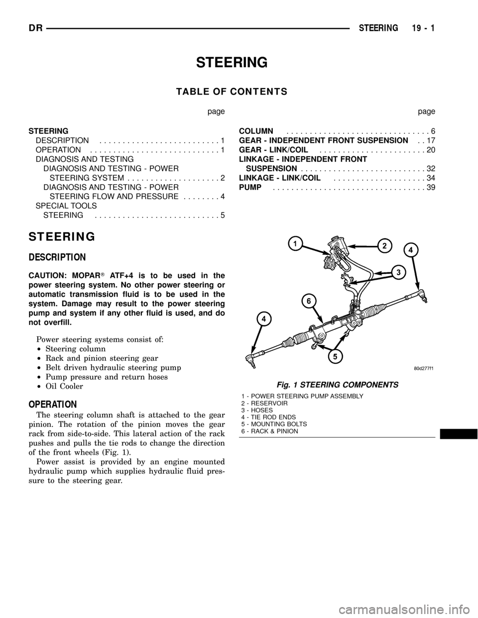
of the front wheels (Fig. 1).
Power assist is provided by an engine mounted
hydraulic pump which supplies hydraulic fluid pres-
sure to the steering gear.
Fig. 1 STEERING COMPONENTS
1 - POWER STEERING PUMP ASSEMBLY
2 - RESERVOIR
3 - HOSES
4 - TIE ROD ENDS
5 - MOUNTING BOLTS
6 - RACK & PINION
DRSTEERING 19 - 1
Page 1657 of 2627

DIAGNOSIS AND TESTING
DIAGNOSIS AND TESTING - POWER STEERING
SYSTEM
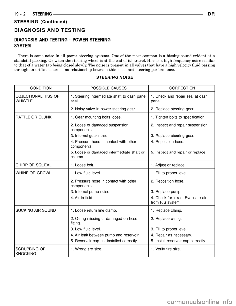
There is some noise in all power steering systems. One of the most common is a hissing sound evident at a
standstill parking. Or when the steering wheel is at the end of it's travel. Hiss is a high frequency noise similar
to that of a water tap being closed slowly. The noise is present in all valves that have a high velocity fluid passing
through an orifice. There is no relationship between this noise and steering performance.
STEERING NOISE
CONDITION POSSIBLE CAUSES CORRECTION
OBJECTIONAL HISS OR
WHISTLE1. Steering intermediate shaft to dash panel
seal.1. Check and repair seal at dash
panel.
2. Noisy valve in power steering gear. 2. Replace steering gear.
RATTLE OR CLUNK 1. Gear mounting bolts loose. 1. Tighten bolts to specification.
2. Loose or damaged suspension
components.2. Inspect and repair suspension.
3. Internal gear noise. 3. Replace steering gear.
4. Pressure hose in contact with other
components.4. Reposition hose.
5. Loose or damaged intermediate shaft or
column.5. Inspect and repair or replace.
CHIRP OR SQUEAL 1. Loose belt. 1. Adjust or replace.
WHINE OR GROWL 1. Low fluid level. 1. Fill to proper level.
2. Pressure hose in contact with other
components.2. Reposition hose.
3. Internal pump noise. 3. Replace pump.
4. Air in fluid 4. Check for lekas, Evacuate air
from P/S system.
SUCKING AIR SOUND 1. Loose return line clamp. 1. Replace clamp.
2. O-ring missing or damaged on hose
fitting.2. Replace o-ring.
3. Low fluid level. 3. Fill to proper level.
4. Air leak between pump and reservoir. 4. Repair as necessary.
5. Reservoir cap not installed correctly. 5. Install reservoir cap correctly.
SCRUBBING OR
KNOCKING1. Wrong tire size. 1. Verify tire size.
19 - 2 STEERINGDR
STEERING (Continued)
Page 1658 of 2627

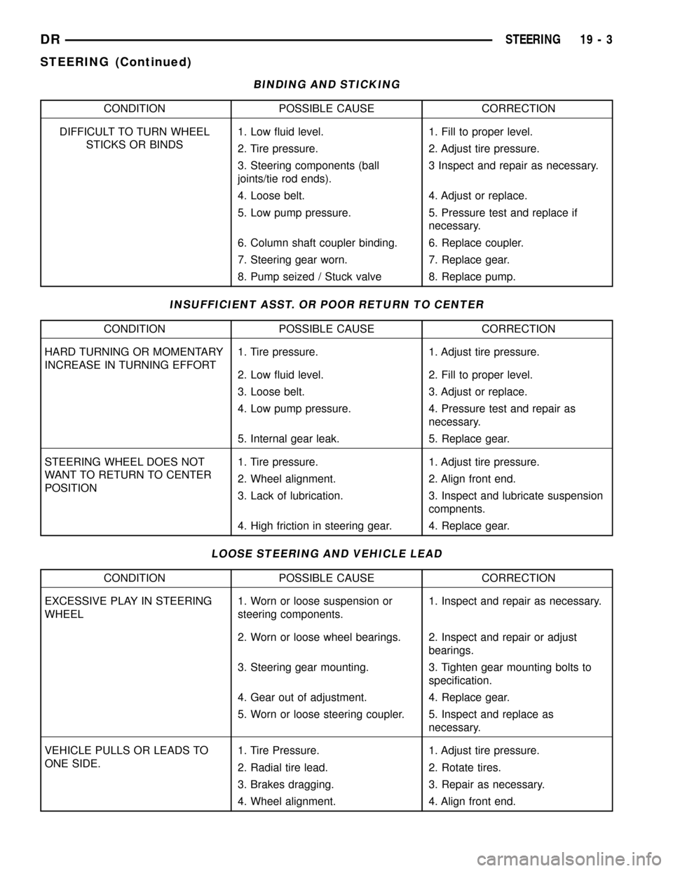
BINDING AND STICKING
CONDITION POSSIBLE CAUSE CORRECTION
DIFFICULT TO TURN WHEEL
STICKS OR BINDS1. Low fluid level. 1. Fill to proper level.
2. Tire pressure. 2. Adjust tire pressure.
3. Steering components (ball
joints/tie rod ends).3 Inspect and repair as necessary.
4. Loose belt. 4. Adjust or replace.
5. Low pump pressure. 5. Pressure test and replace if
necessary.
6. Column shaft coupler binding. 6. Replace coupler.
7. Steering gear worn. 7. Replace gear.
8. Pump seized / Stuck valve 8. Replace pump.
INSUFFICIENT ASST. OR POOR RETURN TO CENTER
CONDITION POSSIBLE CAUSE CORRECTION
HARD TURNING OR MOMENTARY
INCREASE IN TURNING EFFORT1. Tire pressure. 1. Adjust tire pressure.
2. Low fluid level. 2. Fill to proper level.
3. Loose belt. 3. Adjust or replace.
4. Low pump pressure. 4. Pressure test and repair as
necessary.
5. Internal gear leak. 5. Replace gear.
STEERING WHEEL DOES NOT
WANT TO RETURN TO CENTER
POSITION1. Tire pressure. 1. Adjust tire pressure.
2. Wheel alignment. 2. Align front end.
3. Lack of lubrication. 3. Inspect and lubricate suspension
compnents.
4. High friction in steering gear. 4. Replace gear.
LOOSE STEERING AND VEHICLE LEAD
CONDITION POSSIBLE CAUSE CORRECTION
EXCESSIVE PLAY IN STEERING
WHEEL1. Worn or loose suspension or
steering components.1. Inspect and repair as necessary.
2. Worn or loose wheel bearings. 2. Inspect and repair or adjust
bearings.
3. Steering gear mounting. 3. Tighten gear mounting bolts to
specification.
4. Gear out of adjustment. 4. Replace gear.
5. Worn or loose steering coupler. 5. Inspect and replace as
necessary.
VEHICLE PULLS OR LEADS TO
ONE SIDE.1. Tire Pressure. 1. Adjust tire pressure.
2. Radial tire lead. 2. Rotate tires.
3. Brakes dragging. 3. Repair as necessary.
4. Wheel alignment. 4. Align front end.
DRSTEERING 19 - 3
STEERING (Continued)
Page 1659 of 2627

DIAGNOSIS AND TESTING - POWER STEERING
FLOW AND PRESSURE
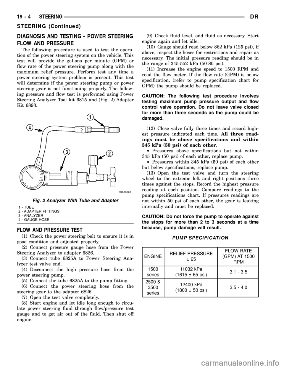
The following procedure is used to test the opera-
tion of the power steering system on the vehicle. This
test will provide the gallons per minute (GPM) or
flow rate of the power steering pump along with the
maximum relief pressure. Perform test any time a
power steering system problem is present. This test
will determine if the power steering pump or power
steering gear is not functioning properly. The follow-
ing pressure and flow test is performed using Power
Steering Analyzer Tool kit 6815 and (Fig. 2) Adapter
Kit 6893.
FLOW AND PRESSURE TEST
(1) Check the power steering belt to ensure it is in
good condition and adjusted properly.
(2) Connect pressure gauge hose from the Power
Steering Analyzer to adapter 6826.
(3) Connect tube 6825A to Power Steering Ana-
lyzer test valve end.
(4) Disconnect the high pressure hose from the
power steering pump.
(5) Connect the tube 6825A to the pump fitting.
(6) Connect the power steering hose from the
steering gear to the adapter 6826.
(7) Open the test valve completely.
(8) Start engine and let idle long enough to circu-
late power steering fluid through flow/pressure test
gauge and to get air out of the fluid. Then shut off
engine.(9) Check fluid level, add fluid as necessary. Start
engine again and let idle.
(10) Gauge should read below 862 kPa (125 psi), if
above, inspect the hoses for restrictions and repair as
necessary. The initial pressure reading should be in
the range of 345-552 kPa (50-80 psi).
(11) Increase the engine speed to 1500 RPM and
read the flow meter. If the flow rate (GPM) is below
specification, (refer to pump specification chart for
GPM) the pump should be replaced.
CAUTION: The following test procedure involves
testing maximum pump pressure output and flow
control valve operation. Do not leave valve closed
for more than three seconds as the pump could be
damaged.
(12) Close valve fully three times and record high-
est pressure indicated each time.All three read-
ings must be above specifications and within
345 kPa (50 psi) of each other.
²Pressures above specifications but not within
345 kPa (50 psi) of each other, replace pump.
²Pressures within 345 kPa (50 psi) of each other
but below specifications, replace pump.
(13) Open the test valve and turn the steering
wheel to the extreme left and right positions three
times against the stops. Record the highest pressure
reading at each position. Compare readings to the
pump specifications chart. If pressures readings are
not within 50 psi of each other, the gear is leaking
internally and must be replaced.
CAUTION: Do not force the pump to operate against
the stops for more than 2 to 3 seconds at a time
because, pump damage will result.PUMP SPECIFICATION
ENGINERELIEF PRESSURE
65FLOW RATE
(GPM) AT 1500
RPM
1500
series11032 kPa
(1615 65 psi)3.1 - 3.5
2500 &
3500
series12400 kPa
(1800 50 psi)3.5 - 4.0
Fig. 2 Analyzer With Tube and Adapter
1 - TUBE
2 - ADAPTER FITTINGS
3 - ANALYZER
4 - GAUGE HOSE
19 - 4 STEERINGDR
STEERING (Continued)
Page 1694 of 2627

PUMP
TABLE OF CONTENTS
page page
PUMP
DESCRIPTION.........................39
OPERATION...........................40
DIAGNOSIS AND TESTING - PUMP LEAKAGE . 40
STANDARD PROCEDURE
STANDARD PROCEDURE - POWER
STEERING PUMP - INITIAL OPERATION....40
STANDARD PROCEDURE - FLUSHING
POWER STEERING SYSTEM............40
REMOVAL
REMOVAL - GAS......................41
REMOVAL - DIESEL...................41
INSTALLATION
INSTALLATION - GAS..................42
INSTALLATION - DIESEL................42
SPECIFICATIONS
TORQUE CHART......................42
FLUID
DESCRIPTION.........................43
STANDARD PROCEDURE - POWER
STEERING FLUID LEVEL CHECKING......43
FLUID COOLER
REMOVAL.............................43
INSTALLATION.........................43
HOSES - I.F.S.
REMOVAL
REMOVAL - RETURN HOSE - GEAR TO
COOLER............................44
REMOVAL - PRESSURE HOSE...........44
REMOVAL - RETURN HOSE - RESERVOIR
TO COOLER.........................44INSTALLATION
INSTALLATION - RETURN HOSE - GEAR TO
COOLER............................44
INSTALLATION - PRESSURE HOSE.......44
INSTALLATION - RETURN HOSE -
RESERVOIR TO COOLER...............44
HOSES - LINK/COIL
REMOVAL
REMOVAL - RETURN HOSE - GEAR TO
COOLER............................45
REMOVAL - PRESSURE HOSE...........45
REMOVAL - RETURN HOSE - RESERVOIR
TO COOLER.........................45
INSTALLATION
INSTALLATION - RETURN HOSE - GEAR TO
COOLER............................45
INSTALLATION - PRESSURE HOSE.......45
INSTALLATION - RETURN HOSE -
RESERVOIR TO COOLER...............45
POWER STEERING PRESSURE SWITCH
DESCRIPTION.........................46
OPERATION...........................46
REMOVAL - 3.7L & 5.7L..................46
INSTALLATION - 3.7L & 5.7L...............46
PULLEY
REMOVAL.............................47
INSTALLATION.........................47
RESERVOIR
REMOVAL.............................47
INSTALLATION.........................47
PUMP
DESCRIPTION
CAUTION: MOPARTATF+4 is to be used in the
power steering system. No other power steering or
automatic transmission fluid is to be used in the
system. Damage may result to the power steering
pump and system if any other fluid is used, and do
not overfill.The pump is connected to the steering gear via the
pressure hose and the return hose. The pump shaft
has a pressed-on pulley that is belt driven by the
crankshaft pulley.
All vehicles are equipped with a power steering
fluid cooler.
NOTE: Power steering pumps are not interchange-
able with pumps installed on other vehicles.
DRPUMP 19 - 39
Page 1695 of 2627

OPERATION
Hydraulic pressure is provided for the power steer-
ing gear by the belt driven power steering pump (Fig.
1). The power steering pumps are constant flow rate
and displacement, vane-type pumps.
DIAGNOSIS AND TESTING - PUMP LEAKAGE
The pump is serviced as an assembly and should
not be disassembled. The plastic pump reservoir and
the reservoir o-rings can be replaced.
Check for leaks in the following areas:
²Pump shaft seal behind the pulley
²Pump to reservoir O-ring
²Reservoir cap
²Pressure and return lines
²Flow control valve fitting
STANDARD PROCEDURE
STANDARD PROCEDURE - POWER STEERING
PUMP - INITIAL OPERATION
WARNING: THE FLUID LEVEL SHOULD BE
CHECKED WITH ENGINE OFF TO PREVENT INJURY
FROM MOVING COMPONENTS.
CAUTION: MOPARTATF+4 is to be used in the
power steering system. No other power steering or
automatic transmission fluid is to be used in the
system. Damage may result to the power steeringpump and system if any other fluid is used, and do
not overfill.
Wipe filler cap clean, then check the fluid level.
The dipstick should indicateCOLDwhen the fluid is
at normal temperature.
(1) Turn steering wheel all the way to the left
(2) Fill the pump fluid reservoir to the proper level
and let the fluid settle for at least two (2) minutes.
(3) Raise the front wheels off the ground.
(4) Slowly turn the steering wheel lock-to-lock 20
times with the engine off while checking the fluid
level.
NOTE: For vehicles with long return lines or oil
coolers turn wheel 40 times.
(5) Start the engine. With the engine idling main-
tain the fluid level.
(6) Lower the front wheels and let the engine idle
for two minutes.
(7) Turn the steering wheel in both direction and
verify power assist and quiet operation of the pump.
If the fluid is extremely foamy or milky looking,
allow the vehicle to stand a few minutes and repeat
the procedure.
CAUTION: Do not run a vehicle with foamy fluid for
an extended period. This may cause pump damage.
STANDARD PROCEDURE - FLUSHING POWER
STEERING SYSTEM
Flushing is required when the power steering/hy-
draulic booster system fluid has become contami-
nated. Contaminated fluid in the steering/booster
system can cause seal deterioration and affect steer-
ing gear/booster spool valve operation.
(1) Raise the front end of the vehicle off the
ground until the wheels are free to turn.
(2) Remove the return line from the pump.
NOTE: If vehicle is equipped with a hydraulic
booster remove both return lines from the pump.
(3) Plug the return line port/ports at the pump.
(4) Position the return line/lines into a large con-
tainer to catch the fluid.
(5) While an assistant is filling the pump reservoir
start the engine.
(6) With the engine running at idle turn the wheel
back and forth.
NOTE: Do not contact or hold the wheel against the
steering stops.
(7) Run a quart of fluid through the system then
stop the engine and install the return line/lines.
Fig. 1 POWER STEERING PUMP
1 - 3.7L & 4.7L (6 GROOVE)
PHENOLIC (PLASTIC TYPE) PULLEY
1 - 5.7L,5.9L & 8.0L (7 GROOVE)
PHENOLIC (PLASTIC TYPE) PULLEY
1 - 5.9L DIESEL (8 GROOVE)
STEEL PULLEY
2 - PUMP ASSEMBLY
3 - RESERVOIR
4 - CAP
19 - 40 PUMPDR
PUMP (Continued)