1998 DODGE RAM 1500 steering wheel
[x] Cancel search: steering wheelPage 62 of 2627

INSTALLATION
CAUTION: The left and right side torsion bars are
NOT interchangeable. The bars are identified and
stamped R or L, for right or left. The bars do not
have a front or rear end and can be installed with
either end facing forward.
(1) Insert torsion bar ends into anchor and suspen-
sion arm.
(2) Position the anchor in the frame crossmember.
(3) Install Special Tool - 8686 to the anchor and
the crossmember (Fig. 30).
(4) Increase the tension on the anchor in order to
load the torsion bar.
(5) Install the adjustment bolt and the adjuster
nut.
(6) Turn adjustment bolt clockwise the recorded
amount of turns.
(7) Remove tool - 8686 from the torsion bar cross-
member (Fig. 30).
(8) Install the transfer case skid plate (Refer to 13
- FRAME & BUMPERS/FRAME/TRANSFER CASE
SKID PLATE - INSTALLATION).
(9) Lower vehicle and adjust the front suspension
height (Refer to 2 - SUSPENSION/WHEEL ALIGN-
MENT - STANDARD PROCEDURE).
(10) Perform a wheel alignment (Refer to 2 - SUS-
PENSION/WHEEL ALIGNMENT - STANDARD
PROCEDURE).
UPPER BALL JOINT
DIAGNOSIS AND TESTING - UPPER BALL
JOINT
NOTE: If the ball joint is equipped with a lubrication
fitting, grease the joint then road test the vehicle
before performing test.
(1) Raise the front of the vehicle. Place safety floor
stands under both lower control arms as far outboard
as possible. Lower the vehicle to allow the stands to
support some or all of the vehicle weight.
(2) Remove the front tires.(3) Mount a dial indicator solidly to the frame and
then zero the dial indicator.
(4) Position dial indicator plunger on the topside of
the upper ball joint (Fig. 32).
NOTE: The dial indicator plunger must be perpen-
dicular to the machined surface of the ball joint
(Fig. 32).
NOTE: Use care not to pry or tear the ball joint
boot, when checking the free play.
(5) Position a pry bar between the steering
knuckle and the upper control arm. Pry upwards on
the upper control arm (Fig. 32).
(6) If the travel exceeds 0.5 mm (0.020 in.), replace
the upper control arm since the upper ball joint is
integral to the arm (Refer to 2 - SUSPENSION/
FRONT/UPPER CONTROL ARM - REMOVAL).
(7) If the upper ball joint is within specs reinstall
the front tires (Refer to 22 - TIRES/WHEELS/
WHEELS - STANDARD PROCEDURE).
Fig. 32 UPPER BALL JOINT PLAY
1 - DIAL INDICATOR
2 - UPPER CONTROL ARM
3-PRYBAR
4 - KNUCKLE
5 - BALL JOINT BOOT
DRFRONT - INDEPENDENT FRONT SUSPENSION 2 - 27
TORSION BAR (Continued)
Page 63 of 2627

UPPER CONTROL ARM
REMOVAL
(1) Raise and support vehicle.
(2) Remove wheel and tire assembly.
(3) Remove the nut from upper ball joint.
(4) Separate upper ball joint from the steering
knuckle with Remover 8677 (Fig. 33)
CAUTION: When installing Remover 8677 to sepa-
rate the ball joint, be careful not to damage the ball
joint seal.(5) Remove the control arm pivot bolts and remove
control arm (Fig. 34).
INSTALLATION
(1) Position the control arm into the frame brack-
ets. Install bolts and tighten to 132 N´m (97 ft.
lbs.)(LD) or 170 N´m (125 ft. lbs.)(HD 4X2 only).
(2) Insert the ball joint in steering knuckle and
tighten the upper ball joint nut to 54 N´m (40 ft.
lbs.)(on 1500 series only an additional 90É turn is
required).
(3) Install the wheel and tire assembly,(Refer to 22
- TIRES/WHEELS/WHEELS - STANDARD PROCE-
DURE).
(4) Remove the support and lower vehicle.
(5) Perform a wheel alignment, (Refer to 2 - SUS-
PENSION/WHEEL ALIGNMENT - STANDARD
PROCEDURE).
Fig. 33 UPPER BALL JOINT SEPARATION
1 - UPPER CONTROL ARM
2 - REMOVER
3 - STEERING KNUCKLE
Fig. 34 UPPER CONTROL ARM
1 - REAR PIVOT BOLT
2 - FRONT PIVOT BOLT
3 - UPPER CONTROL ARM
2 - 28 FRONT - INDEPENDENT FRONT SUSPENSIONDR
Page 66 of 2627

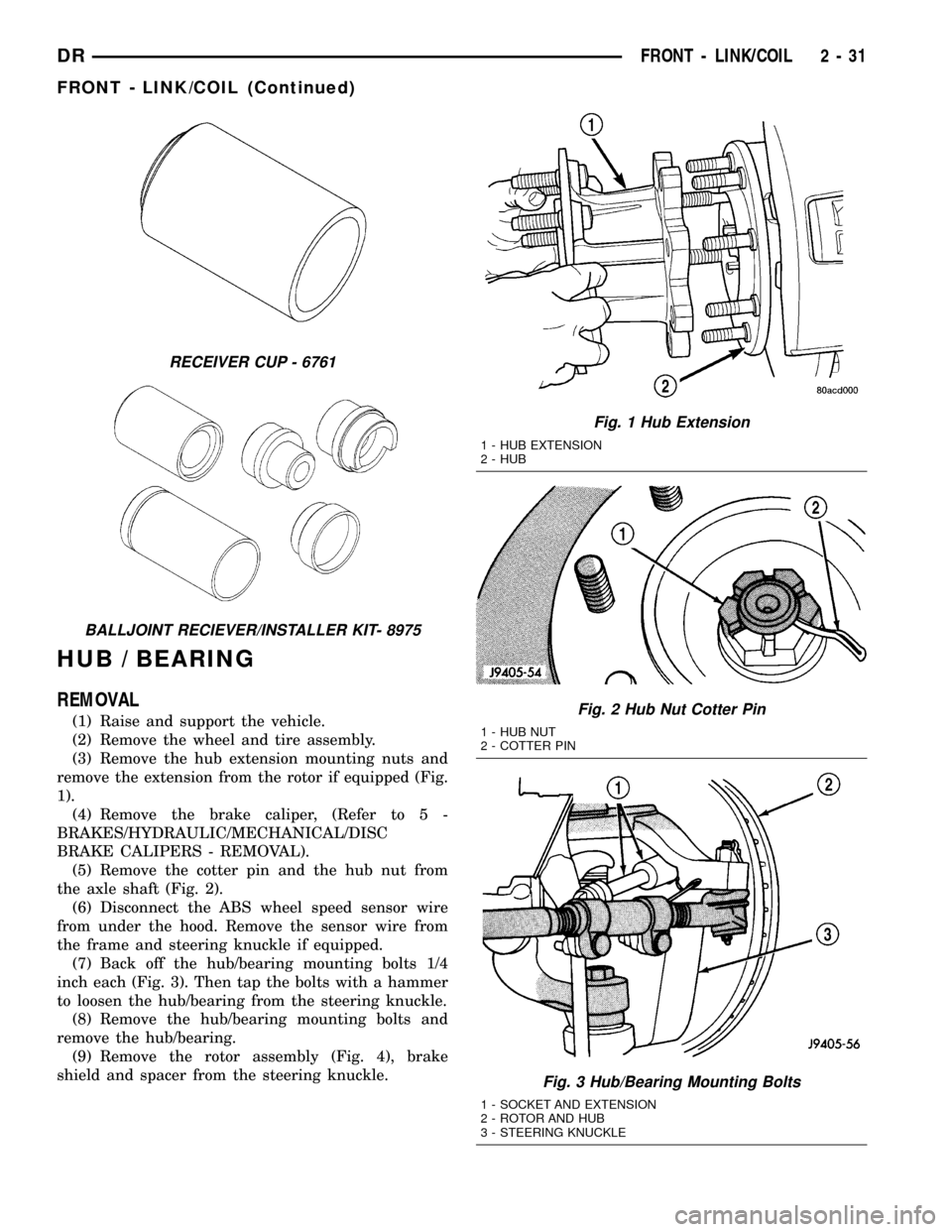
HUB / BEARING
REMOVAL
(1) Raise and support the vehicle.
(2) Remove the wheel and tire assembly.
(3) Remove the hub extension mounting nuts and
remove the extension from the rotor if equipped (Fig.
1).
(4) Remove the brake caliper, (Refer to 5 -
BRAKES/HYDRAULIC/MECHANICAL/DISC
BRAKE CALIPERS - REMOVAL).
(5) Remove the cotter pin and the hub nut from
the axle shaft (Fig. 2).
(6) Disconnect the ABS wheel speed sensor wire
from under the hood. Remove the sensor wire from
the frame and steering knuckle if equipped.
(7) Back off the hub/bearing mounting bolts 1/4
inch each (Fig. 3). Then tap the bolts with a hammer
to loosen the hub/bearing from the steering knuckle.
(8) Remove the hub/bearing mounting bolts and
remove the hub/bearing.
(9) Remove the rotor assembly (Fig. 4), brake
shield and spacer from the steering knuckle.
RECEIVER CUP - 6761
BALLJOINT RECIEVER/INSTALLER KIT- 8975
Fig. 1 Hub Extension
1 - HUB EXTENSION
2 - HUB
Fig. 2 Hub Nut Cotter Pin
1 - HUB NUT
2 - COTTER PIN
Fig. 3 Hub/Bearing Mounting Bolts
1 - SOCKET AND EXTENSION
2 - ROTOR AND HUB
3 - STEERING KNUCKLE
DRFRONT - LINK/COIL 2 - 31
FRONT - LINK/COIL (Continued)
Page 67 of 2627

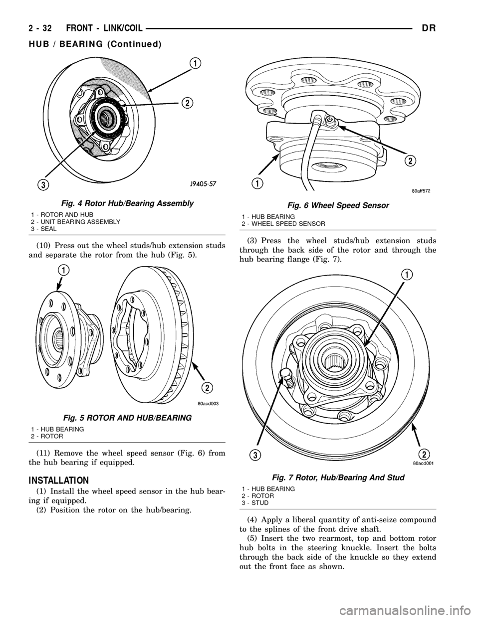
(10) Press out the wheel studs/hub extension studs
and separate the rotor from the hub (Fig. 5).
(11) Remove the wheel speed sensor (Fig. 6) from
the hub bearing if equipped.
INSTALLATION
(1) Install the wheel speed sensor in the hub bear-
ing if equipped.
(2) Position the rotor on the hub/bearing.(3) Press the wheel studs/hub extension studs
through the back side of the rotor and through the
hub bearing flange (Fig. 7).
(4) Apply a liberal quantity of anti-seize compound
to the splines of the front drive shaft.
(5) Insert the two rearmost, top and bottom rotor
hub bolts in the steering knuckle. Insert the bolts
through the back side of the knuckle so they extend
out the front face as shown.
Fig. 4 Rotor Hub/Bearing Assembly
1 - ROTOR AND HUB
2 - UNIT BEARING ASSEMBLY
3 - SEAL
Fig. 5 ROTOR AND HUB/BEARING
1 - HUB BEARING
2 - ROTOR
Fig. 6 Wheel Speed Sensor
1 - HUB BEARING
2 - WHEEL SPEED SENSOR
Fig. 7 Rotor, Hub/Bearing And Stud
1 - HUB BEARING
2 - ROTOR
3 - STUD
2 - 32 FRONT - LINK/COILDR
HUB / BEARING (Continued)
Page 68 of 2627

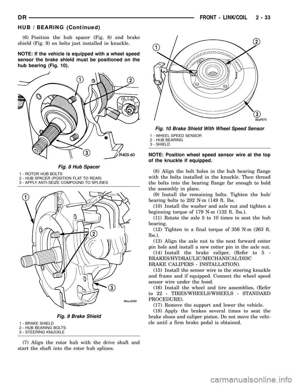
(6) Position the hub spacer (Fig. 8) and brake
shield (Fig. 9) on bolts just installed in knuckle.
NOTE: If the vehicle is equipped with a wheel speed
sensor the brake shield must be positioned on the
hub bearing (Fig. 10).
(7) Align the rotor hub with the drive shaft and
start the shaft into the rotor hub splines.NOTE: Position wheel speed sensor wire at the top
of the knuckle if equipped.
(8) Align the bolt holes in the hub bearing flange
with the bolts installed in the knuckle. Then thread
the bolts into the bearing flange far enough to hold
the assembly in place.
(9) Install the remaining bolts. Tighten the hub/
bearing bolts to 202 N´m (149 ft. lbs.
(10) Install the washer and axle nut and tighten a
beginning torque of 179 N´m (132 ft. lbs.).
(11) Rotate the axle 5 to 10 times to seat the hub
bearing.
(12) Tighten to a final torque of 356 N´m (263 ft.
lbs.).
(13) Align the axle nut to the next forward cotter
pin hole and install a new cotter pin in the axle nut.
(14) Install the brake caliper, (Refer to 5 -
BRAKES/HYDRAULIC/MECHANICAL/DISC
BRAKE CALIPERS - INSTALLATION).
(15) Install the sensor wire to the steering knuckle
and frame and if equipped. Connect the wheel speed
sensor wire under the hood.
(16) Install the wheel and tire assemblies, (Refer
to 22 - TIRES/WHEELS/WHEELS - STANDARD
PROCEDURE).
(17) Remove the support and lower the vehicle.
(18) Apply the brakes several times to seat the
brake shoes and caliper piston. Do not move the vehi-
cle until a firm brake pedal is obtained.
Fig. 8 Hub Spacer
1 - ROTOR HUB BOLTS
2 - HUB SPACER (POSITION FLAT TO REAR)
3 - APPLY ANTI-SEIZE COMPOUND TO SPLINES
Fig. 9 Brake Shield
1 - BRAKE SHIELD
2 - HUB BEARING BOLTS
3 - STEERING KNUCKLE
Fig. 10 Brake Shield With Wheel Speed Sensor
1 - WHEEL SPEED SENSOR
2 - HUB BEARING
3 - SHIELD
DRFRONT - LINK/COIL 2 - 33
HUB / BEARING (Continued)
Page 101 of 2627

HALF SHAFT
TABLE OF CONTENTS
page page
HALF SHAFT
CAUTION.............................20
DIAGNOSIS AND TESTING................20
REMOVAL.............................20
INSTALLATION.........................21
SPECIFICATIONS.......................21
SPECIAL TOOLS.......................21CV JOINT-OUTER
REMOVAL.............................22
INSTALLATION.........................23
CV JOINT-INNER
REMOVAL.............................25
INSTALLATION.........................25
HALF SHAFT
CAUTION
CAUTION:: Never grasp half shaft assembly by the
boots. This may cause the boot to pucker or crease
and reduce the service life of the boot.
Avoid over angulating or stroking the C/V joints
when handling the half shaft.
Half shafts exposed to battery acid, transmission
fluid, brake fluid, differential fluid or gasoline may
cause the boots to deteriorate. Failure to heed cau-
tion may result in damage.
DIAGNOSIS AND TESTING
Check inboard and outboard C/V joint for leaking
grease. This is a sign of boot or boot clamp damage.
NOISE/VIBRATION IN TURNS
A clicking noise or vibration in turns could be
caused by a damaged outer C/V or inner tripod joint
seal boot or seal boot clamps. This will result in the
loss/contamination of the joint grease, resulting in
inadequate lubrication of the joint. Noise could also
be caused by another component of the vehicle com-
ing in contact with the half shafts.
CLUNKING NOISE DURING ACCELERATION
This noise may be a damaged or worn C/V joint. A
torn boot or loose/missing clamp on the inner/outer
joint which has allowed the grease to be lost will
damage the C/V joint.
SHUDDER/VIBRATION DURING ACCELERATION
This could be a worn/damaged inner tripod joint or
a sticking tripod joint. Improper wheel alignment
may also cause a shudder or vibration.
VIBRATION AT HIGHWAY SPEEDS
This problem could be a result of out of balance
front tires or tire/wheel runout. Foreign material
(mud, etc.) packed on the backside of the wheel(s)
will also cause a vibration.
REMOVAL
(1) With vehicle in neutral, position vehicle on
hoist.
(2) Remove half shaft hub nut.
(3) Remove brake caliper and rotor.
(4) Position hydraulic jack under lower suspension
arm and raise jack to unload rebound bumper.
(5) Remove lower shock absorber bolt.
(6) Remove upper ball joint nut and seperate ball
with Remover 8677 (Fig. 1).
(7) Disengage inner C/V joint from axle shaft with
two pry bars between the C/V housing and axle hous-
ing.
Fig. 1 UPPER BALL JOINT SEPARATION
1 - UPPER CONTROL ARM
2 - REMOVER
3 - STEERING KNUCKLE
3 - 20 HALF SHAFTDR
Page 138 of 2627

Condition Possible Causes Correction
Gear Teeth Broke 1. Overloading. 1. Replace gears. Examine other
gears and bearings for possible
damage.
2. Erratic clutch operation. 2. Replace gears and examine the
remaining parts for damage. Avoid
erratic clutch operation.
3. Ice-spotted pavement. 3. Replace gears and examine
remaining parts for damage.
4. Improper adjustments. 4. Replace gears and examine
remaining parts for damage. Ensure
ring gear backlash is correct.
Axle Noise 1. Insufficient lubricant. 1. Fill differential with the correct
fluid type and quantity.
2. Improper ring gear and pinion
adjustment.2. Check ring gear and pinion
contact pattern.
3. Unmatched ring gear and pinion. 3. Replace gears with a matched
ring gear and pinion.
4. Worn teeth on ring gear and/or
pinion.4. Replace ring gear and pinion.
5. Loose pinion bearings. 5. Adjust pinion bearing pre-load.
6. Loose differential bearings. 6. Adjust differential bearing
pre-load.
7. Mis-aligned or sprung ring gear. 7. Measure ring gear run-out.
Replace components as necessary.
8. Loose differential bearing cap
bolts.8. Inspect differential components
and replace as necessary. Ensure
that the bearing caps are torqued
tot he proper specification.
9. Housing not machined properly. 9. Replace housing.
REMOVAL
(1) With vehicle in neutral, position vehicle on
hoist.
(2) Remove brake calipers and rotors.
(3) Disconnect ABS wheel speed sensors.
(4) Disconnect axle vent hose.
(5) Remove front propeller shaft.
(6) Remove stabilizer bar links at the axle brack-
ets (Fig. 1).
(7) Disconnect shock absorbers from axle brackets
(Fig. 2).
(8) Remove track bar from the axle bracket (Fig.
3).
(9) Remove tie rod and drag link (Fig. 4) from the
steering knuckles.
(10) Position lift under the axle assembly and
secure axle to lift.
(11) Mark suspension alignment cams for installa-
tion reference.
Fig. 1 STABILIZER LINK
1 - PULLER C-3894-A
2 - LINK
DRFRONT AXLE - 9 1/4 AA 3 - 57
FRONT AXLE - 9 1/4 AA (Continued)
Page 140 of 2627

(7) Connect track bar to the axle bracket and
install the bolt. Do not tighten at this time.
(8) Install shock absorber and tighten bolts to 121
N´m (89 ft. lbs.).
(9) Install stabilizer bar link to the axle bracket.
Tighten the nut to 68 N´m (50 ft. lbs.).
(10) Install drag link and tie rod to the steering
knuckles and tighten the nuts to 108 N´m (80 ft.
lbs.).
(11) Install ABS wheel speed sensors.
(12) Install rotors and brake calipers.
(13) Connect the axle vent hose.
(14) Install front propeller shaft.
(15) With vehicle on the ground, tighten upper
suspension arm nuts at axle to 149 N´m (110 ft. lbs.).
Tighten upper suspension arm nuts at frame to 149
N´m (110 ft. lbs.).
(16) With vehicle on the ground, tighten lower sus-
pension arm nuts at axle to 190 N´m (140 ft. lbs.).
Tighten the lower suspension arm nuts at frame to
190 N´m (140 ft. lbs.).
(17) Tighten track bar bolt at the axle bracket to
176 N´m (130 ft. lbs.).
(18) Check front wheel alignment.
ADJUSTMENTS
Ring and pinion gears are supplied as matched
sets. Compensation for pinion depth variance is
achieved with a select shim. located between the rear
pinion bearing and pinion gear head.
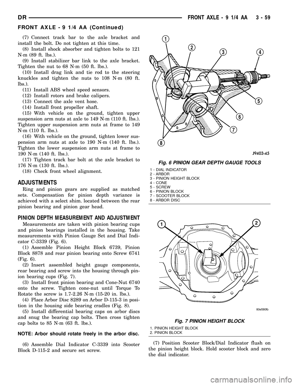
PINION DEPTH MEASUREMENT AND ADJUSTMENT
Measurements are taken with pinion bearing cups
and pinion bearings installed in the housing. Take
measurements with Pinion Gauge Set and Dial Indi-
cator C-3339 (Fig. 6).
(1) Assemble Pinion Height Block 6739, Pinion
Block 8878 and rear pinion bearing onto Screw 6741
(Fig. 6).
(2) Insert assembled height gauge components,
rear bearing and screw into the housing through pin-
ion bearing cups (Fig. 7).
(3) Install front pinion bearing and Cone-Nut 6740
onto the screw. Tighten cone-nut until Torque To
Rotate the screw is 1.7-2.26 N´m (15-20 in. lbs.).
(4) Place Arbor Disc 8289 on Arbor D-115-3 in posi-
tion in the housing side bearing cradles (Fig. 8).
(5) Install differential bearing caps on arbor discs
and snug the bearing cap bolts. Then cross tighten
cap bolts to 85 N´m (63 ft. lbs.).
NOTE: Arbor should rotate freely in the arbor disc.
(6) Assemble Dial Indicator C-3339 into Scooter
Block D-115-2 and secure set screw.(7) Position Scooter Block/Dial Indicator flush on
the pinion height block. Hold scooter block and zero
the dial indicator.
Fig. 6 PINION GEAR DEPTH GAUGE TOOLS
1 - DIAL INDICATOR
2 - ARBOR
3 - PINION HEIGHT BLOCK
4 - CONE
5 - SCREW
6 - PINION BLOCK
7 - SCOOTER BLOCK
8 - ARBOR DISC
Fig. 7 PINION HEIGHT BLOCK
1. PINION HEIGHT BLOCK
2. PINION BLOCK
DRFRONT AXLE - 9 1/4 AA 3 - 59
FRONT AXLE - 9 1/4 AA (Continued)