1998 DODGE RAM 1500 roof
[x] Cancel search: roofPage 2324 of 2627
FORE/AFT
NOTE: Fore/aft (lateral) door adjustment is done by
loosening the hinge to the hinge pillar fasteners
one hinge at a time and moving the door to the cor-
rect position.
(1) Support the door with a suitable lifting device.
(2) Loosen the hinge to hinge pillar fasteners.
(Refer to 23 - BODY/DOORS - REAR/HINGE -
REMOVAL)
(3) Adjust the door to the correct position. (Refer
to 23 - BODY/BODY STRUCTURE/GAP AND
FLUSH - SPECIFICATIONS)
(4) Tighten to hinge pillar fasteners to 28 N´m (21
ft. lbs.). (Refer to 23 - BODY/DOORS - REAR/HINGE
- INSTALLATION)
NOTE: Use a suitable body sealer on the hinge to
body mating surfaces.
UP/DOWN
NOTE: Up/down door adjustment is done by loosen-
ing either the hinge to the hinge pillar fasteners orthe hinge to door fasteners and moving the door to
the correct position.
NOTE: When adjustment of the door requires the
loosening of the door to hinge fasteners, it will be
necessary to separate the epoxy bonded washers
with a chisel or other suitable tool.
NOTE: When the up/down adjustments are done
correctly, the top of the door is positioned over
flush to the roof. (Refer to 23 - BODY/BODY STRUC-
TURE/GAP AND FLUSH - SPECIFICATIONS)
(1) Support the door with a suitable lifting device.
(2) Remove the latch striker. (Refer to 23 - BODY/
DOORS - REAR/LATCH STRIKER - REMOVAL)
(3) Loosen the hinge to hinge pillar fasteners
(Refer to 23 - BODY/DOORS - REAR/HINGE -
REMOVAL) or loosen the hinge to door fasteners
(Refer to 23 - BODY/DOORS - REAR/DOOR -
REMOVAL).
(4) Adjust the door to the correct position. (Refer
to 23 - BODY/BODY STRUCTURE/GAP AND
FLUSH - SPECIFICATIONS)
(5) Tighten to hinge pillar fasteners or the door to
hinges fasteners and fasteners to 28 N´m (21 ft. lbs.).
(Refer to 23 - BODY/DOORS - REAR/HINGE -
INSTALLATION)
(6) Install the latch striker. (Refer to 23 - BODY/
DOORS - REAR/LATCH STRIKER - INSTALLA-
TION)
IN/OUT
NOTE: In/out door adjustment is done by loosening
the hinge to door fasteners one hinge at a time and
moving the door to the correct position.
NOTE: When adjustment of the door requires the
loosening of the door to hinge fasteners, it will be
necessary to separate the epoxy bonded washers
with a chisel or other suitable tool.
(1) Support the door with a suitable lifting device.
(2) Remove the latch striker. (Refer to 23 - BODY/
DOORS - REAR/LATCH STRIKER - REMOVAL)
(3) Loosen the hinge to door fasteners. (Refer to 23
- BODY/DOORS - REAR/DOOR - REMOVAL)
(4) Adjust the front of the door to the correct posi-
tion. (Refer to 23 - BODY/BODY STRUCTURE/GAP
AND FLUSH - SPECIFICATIONS)
(5) Tighten the door to hinges fasteners to 28 N´m
(21 ft. lbs.).
(6) Install the latch striker. (Refer to 23 - BODY/
DOORS - REAR/LATCH STRIKER - INSTALLA-
TION)
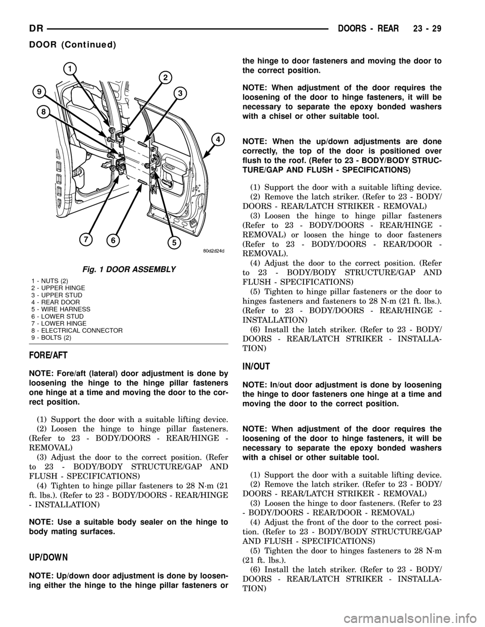
Fig. 1 DOOR ASSEMBLY
1 - NUTS (2)
2 - UPPER HINGE
3 - UPPER STUD
4 - REAR DOOR
5 - WIRE HARNESS
6 - LOWER STUD
7 - LOWER HINGE
8 - ELECTRICAL CONNECTOR
9 - BOLTS (2)
DRDOORS - REAR 23 - 29
DOOR (Continued)
Page 2381 of 2627
STATIONARY GLASS
TABLE OF CONTENTS
page page
BACKLITE
REMOVAL.............................86
INSTALLATION.........................86
BACKLITE VENT GLASS
REMOVAL.............................87
INSTALLATION.........................87WINDSHIELD
WARNING
WINDSHIELD SAFETY PRECAUTIONS.....88
REMOVAL.............................88
INSTALLATION.........................88
BACKLITE
REMOVAL
It is difficult to salvage the backlite during the
removal operation. The backlite is part of the struc-
tural support for the roof. The urethane bonding
used to secure the glass to the fence is difficult to cut
or clean from any surface. Since the molding is set in
urethane, it is unlikely it would be salvaged. Before
removing the backlite, check the availability from the
parts supplier.
The backlite is attached to the window frame with
urethane adhesive. The urethane adhesive is applied
cold and seals the surface area between the window
opening and the glass. The primer adheres the ure-
thane adhesive to the backlite.
(1) Roll down door glass.
(2) Remove headliner. (Refer to 23 - BODY/INTE-
RIOR/HEADLINER - REMOVAL).
(3) On standard cab models remove the upper
b-pillar trim. (Refer to 23 - BODY/INTERIOR/B-PIL-
LAR UPPER TRIM - REMOVAL)
(4) On quad cab models remove the upper c-pillar
trim. (Refer to 23 - BODY/INTERIOR/C-PILLAR
UPPER TRIM - REMOVAL)
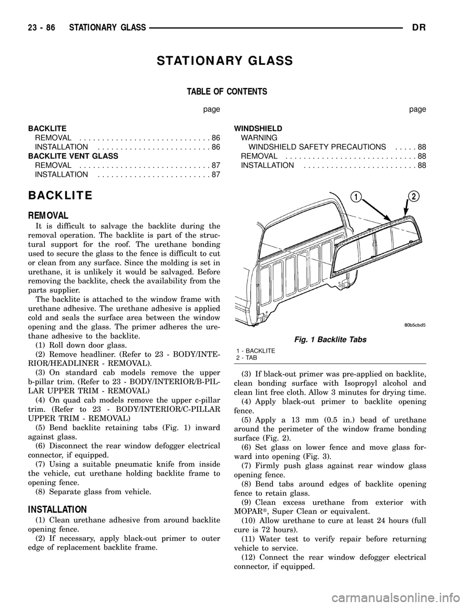
(5) Bend backlite retaining tabs (Fig. 1) inward
against glass.
(6) Disconnect the rear window defogger electrical
connector, if equipped.
(7) Using a suitable pneumatic knife from inside
the vehicle, cut urethane holding backlite frame to
opening fence.
(8) Separate glass from vehicle.
INSTALLATION
(1) Clean urethane adhesive from around backlite
opening fence.
(2) If necessary, apply black-out primer to outer
edge of replacement backlite frame.(3) If black-out primer was pre-applied on backlite,
clean bonding surface with Isopropyl alcohol and
clean lint free cloth. Allow 3 minutes for drying time.
(4) Apply black-out primer to backlite opening
fence.
(5) Apply a 13 mm (0.5 in.) bead of urethane
around the perimeter of the window frame bonding
surface (Fig. 2).
(6) Set glass on lower fence and move glass for-
ward into opening (Fig. 3).
(7) Firmly push glass against rear window glass
opening fence.
(8) Bend tabs around edges of backlite opening
fence to retain glass.
(9) Clean excess urethane from exterior with
MOPARt, Super Clean or equivalent.
(10) Allow urethane to cure at least 24 hours (full
cure is 72 hours).
(11) Water test to verify repair before returning
vehicle to service.
(12) Connect the rear window defogger electrical
connector, if equipped.
Fig. 1 Backlite Tabs
1 - BACKLITE
2-TAB
23 - 86 STATIONARY GLASSDR
Page 2384 of 2627
and 25 mm (1 in.) on the bottom of windshield. Allow
at least three minutes drying time.
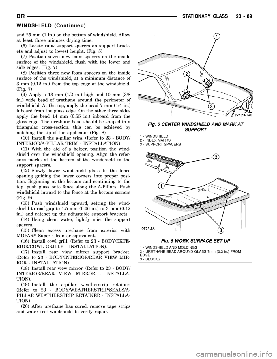
(6) Locatenewsupport spacers on support brack-
ets and adjust to lowest height. (Fig. 5)
(7) Position seven new foam spacers on the inside
surface of the windshield, flush with the lower and
side edges. (Fig. 7)
(8) Position three new foam spacers on the inside
surface of the windshield, at a minimum distance of
3 mm (0.12 in.) from the top edge of the windshield.
(Fig. 7)
(9) Apply a 13 mm (1/2 in.) high and 10 mm (3/8
in.) wide bead of urethane around the perimeter of
windshield. At the top, apply the bead 7 mm (1/4 in.)
inboard from the glass edge. On the other three sides
apply the bead 14 mm (0.55 in.) inboard from the
glass edge. The urethane bead should be shaped in a
triangular cross-section, this can be achieved by
notching the tip of the applicator (Fig. 8).
(10) Install the a-pillar trim. (Refer to 23 - BODY/
INTERIOR/A-PILLAR TRIM - INSTALLATION)
(11) With the aid of a helper, position the wind-
shield over the windshield opening. Align the refer-
ence marks at the bottom of the windshield to the
support spacers.
(12) Slowly lower windshield glass to the fence
opening guiding the lower corners into proper posi-
tion. Beginning at the bottom and continuing to the
top, push glass onto fence along the A-Pillars. Push
windshield inward to the fence at the bottom corners
(Fig. 9).
(13) Push windshield upward, setting the wind-
shield to roof gap to 1.5 mm (0.06 in.) to 3 mm (0.12
in.) and ratchet up the adjustable support brackets.
(14) Using clean water, lightly mist the support
spacers.
(15) Clean excess urethane from exterior with
MOPARtSuper Clean or equivalent.
(16) Install cowl grill. (Refer to 23 - BODY/EXTE-
RIOR/COWL GRILLE - INSTALLATION).
(17) Install rear view mirror support bracket.
(Refer to 23 - BODY/INTERIOR/REAR VIEW MIR-
ROR - INSTALLATION).
(18) Install rear view mirror. (Refer to 23 - BODY/
INTERIOR/REAR VIEW MIRROR - INSTALLA-
TION).
(19) Install the a-pillar weatherstrip retainer.
(Refer to 23 - BODY/WEATHERSTRIP/SEALS/A-
PILLAR WEATHERSTRIP RETAINER - INSTALLA-
TION)
(20) After urethane has cured, remove tape strips
and water test windshield to verify repair.
Fig. 5 CENTER WINDSHIELD AND MARK AT
SUPPORT
1 - WINDSHIELD
2 - INDEX MARKS
3 - SUPPORT SPACERS
Fig. 6 WORK SURFACE SET UP
1 - WINDSHIELD AND MOLDINGS
2 - URETHANE BEAD AROUND GLASS 7mm (0.3 in.) FROM
EDGE
3 - BLOCKS
DRSTATIONARY GLASS 23 - 89
WINDSHIELD (Continued)
Page 2391 of 2627
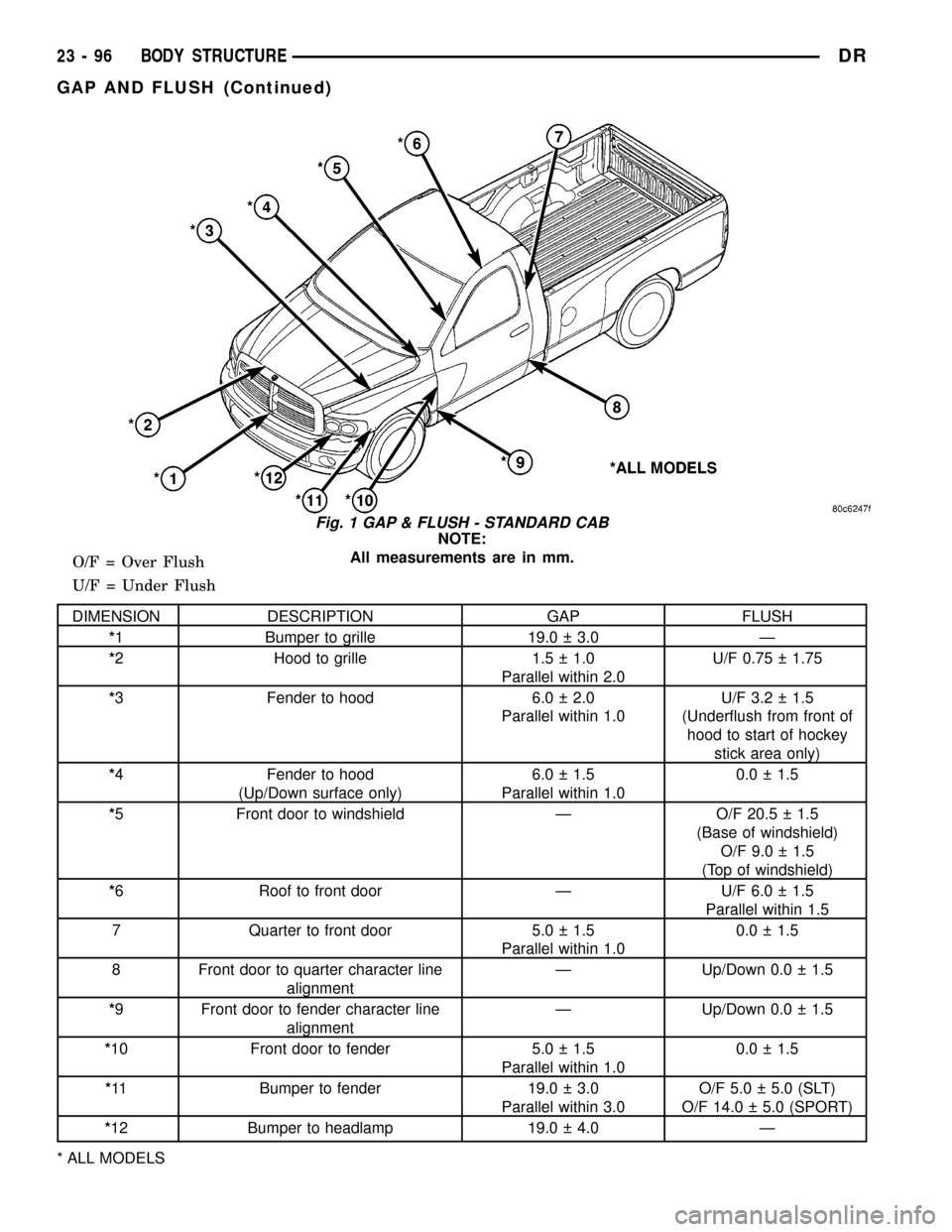
NOTE:
All measurements are in mm.
O/F = Over Flush
U/F = Under Flush
DIMENSION DESCRIPTION GAP FLUSH
*1 Bumper to grille 19.0 3.0 Ð
*2 Hood to grille 1.5 1.0
Parallel within 2.0U/F 0.75 1.75
*3 Fender to hood 6.0 2.0
Parallel within 1.0U/F 3.2 1.5
(Underflush from front of
hood to start of hockey
stick area only)
*4 Fender to hood
(Up/Down surface only)6.0 1.5
Parallel within 1.00.0 1.5
*5 Front door to windshield Ð O/F 20.5 1.5
(Base of windshield)
O/F 9.0 1.5
(Top of windshield)
*6 Roof to front door Ð U/F 6.0 1.5
Parallel within 1.5
7 Quarter to front door 5.0 1.5
Parallel within 1.00.0 1.5
8 Front door to quarter character line
alignmentÐ Up/Down 0.0 1.5
*9 Front door to fender character line
alignmentÐ Up/Down 0.0 1.5
*10 Front door to fender 5.0 1.5
Parallel within 1.00.0 1.5
*11 Bumper to fender 19.0 3.0
Parallel within 3.0O/F 5.0 5.0 (SLT)
O/F 14.0 5.0 (SPORT)
*12 Bumper to headlamp 19.0 4.0 Ð
* ALL MODELS
Fig. 1 GAP & FLUSH - STANDARD CAB
23 - 96 BODY STRUCTUREDR
GAP AND FLUSH (Continued)
Page 2392 of 2627
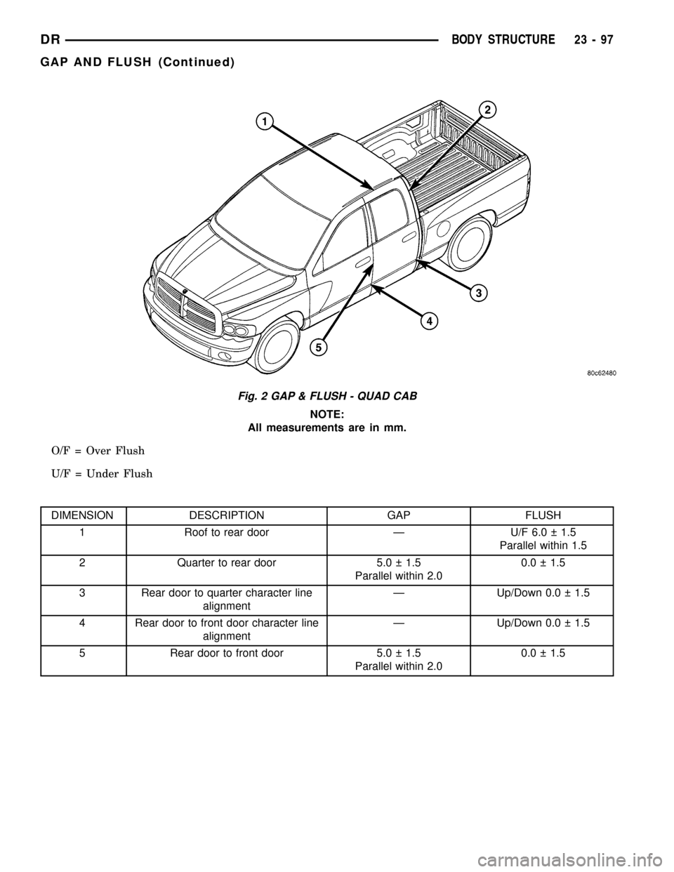
NOTE:
All measurements are in mm.
O/F = Over Flush
U/F = Under Flush
DIMENSION DESCRIPTION GAP FLUSH
1 Roof to rear door Ð U/F 6.0 1.5
Parallel within 1.5
2 Quarter to rear door 5.0 1.5
Parallel within 2.00.0 1.5
3 Rear door to quarter character line
alignmentÐ Up/Down 0.0 1.5
4 Rear door to front door character line
alignmentÐ Up/Down 0.0 1.5
5 Rear door to front door 5.0 1.5
Parallel within 2.00.0 1.5
Fig. 2 GAP & FLUSH - QUAD CAB
DRBODY STRUCTURE 23 - 97
GAP AND FLUSH (Continued)
Page 2397 of 2627
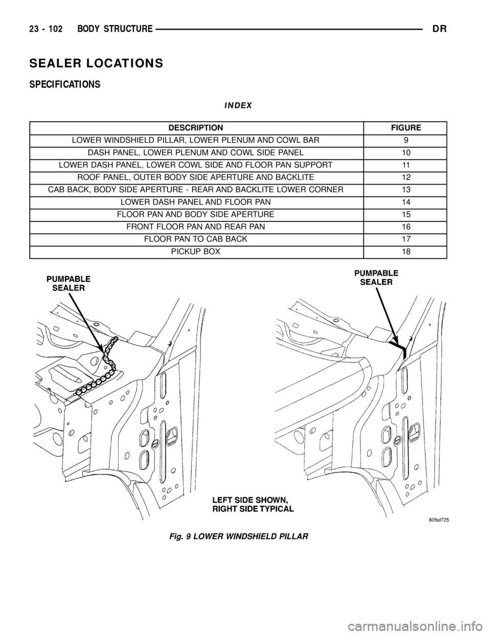
SEALER LOCATIONS
SPECIFICATIONS
INDEX
DESCRIPTION FIGURE
LOWER WINDSHIELD PILLAR, LOWER PLENUM AND COWL BAR 9
DASH PANEL, LOWER PLENUM AND COWL SIDE PANEL 10
LOWER DASH PANEL, LOWER COWL SIDE AND FLOOR PAN SUPPORT 11
ROOF PANEL, OUTER BODY SIDE APERTURE AND BACKLITE 12
CAB BACK, BODY SIDE APERTURE - REAR AND BACKLITE LOWER CORNER 13
LOWER DASH PANEL AND FLOOR PAN 14
FLOOR PAN AND BODY SIDE APERTURE 15
FRONT FLOOR PAN AND REAR PAN 16
FLOOR PAN TO CAB BACK 17
PICKUP BOX 18
Fig. 9 LOWER WINDSHIELD PILLAR
23 - 102 BODY STRUCTUREDR
Page 2400 of 2627
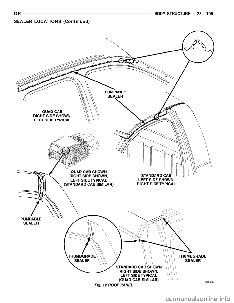
Fig. 12 ROOF PANEL
DRBODY STRUCTURE 23 - 105
SEALER LOCATIONS (Continued)
Page 2416 of 2627
DESCRIPTION FIGURE
STORAGE BIN TO RIGHT AND LEFT REAR FLOOR CROSSMEMBER TO REAR
FLOOR PAN54
RIGHT REAR FRONT SEAT MOUNTING CROSSMEMBER TO LEFT REAR FRONT
SEAT MOUNTING CROSSMEMBER TO REAR FLOOR PAN55
FRONT SEAT MOUNTING FRONT CROSSMEMBER AND STORAGE BIN TO FLOOR
SILL TO FRONT AND REAR FLOOR PAN56
FRONT SEAT MOUNTING FRONT CROSSMEMBER TO UNDERBODY SUPPORT TO
FRONT FLOOR PAN57
A-PILLAR REINFORCEMENT TO INNER BODY SIDE APERTURE TO OUTER BODY
SIDE APERTURE58
A-PILLAR REINFORCEMENT TO FRONT APERTURE EXTENSION TO INNER BODY
SIDE APERTURE TO OUTER BODY SIDE APERTURE59
INNER BODY SIDE APERTURE TO OUTER BODY SIDE APERTURE 60
SHOULDER BELT REINFORCEMENT TO INNER BODY SIDE APERTURE TO OUTER
BODY SIDE APERTURE61
FRONT PILLAR TAPPING PLATES TO INNER BODY SIDE APERTURE TO OUTER
BODY SIDE APERTURE62
INNER BODY SIDE APERTURE TO OUTER BODY SIDE APERTURE 63
C-PILLAR BAFFLE AND OUTER BODY SIDE APERTURE TO INNER BODY SIDE
APERTURE64
A-PILLER REINFORCEMENT TO INNER BODY SIDE APERTURE TO OUTER BODY
SIDE APERTURE65
FRONT EXTENSION PLATE TO INNER BODY SIDE APERTURE TO OUTER BODY
SIDE APERTURE TO A-PILLAR REINFORCEMENT66
OUTER BODY SIDE APERTURE TO INNER BODY SIDE APERTURE 67
B-PILLAR REINFORCEMENT TO INNER BODY SIDE APERTURE TO OUTER BODY
SIDE APERTURE68
UPPER B-PILLAR TAPPING PLATE AND LOWER B-PILLAR TAPPING PLATE TO
OUTER BODY SIDE APERTURE69
UPPER A-PILLAR TAPPING PLATE AND LOWER A-PILLAR TAPPING PLATE TO INNER
BODY SIDE APERTURE70
SEAT BELT MOUNTING PLATES AND REINFORCEMENTS TO INNER BODY SIDE
APERTURE71
OUTER BODY SIDE APERTURE TO INNER BODY SIDE APERTURE 72
C-PILLAR REINFORCEMENTS AND SHOULDER BELT MOUNTING REINFORCEMENT
TO INNER BODY SIDE APERTURE TO OUTER BODY SIDE APERTURE73
SEAT BELT RETRACTOR PLATE TO FLOOR SILL TO INNER BODY SIDE APERTURE
TO OUTER BODY SIDE APERTURE74
FLOOR SILL TO INNER BODY SIDE APERTURE TO OUTER BODY SIDE APERTURE 75
BACK REINFORCEMENT AND CAB BACK PANEL TO REAR FLOOR CROSSMEMBER
AND INNER BODY SIDE APERTURE TO OUTER BODY SIDE APERTURE76
CAB BACK REINFORCEMENT TO CAB BACK PANEL (CHILD TETHERS) 77
COWL SIDE PANEL TO INNER BODY SIDE APERTURE TO OUTER BODY SIDE
APERTURE78
OUTER ROOF PANEL TO OUTER BODY SIDE APERTURE 79
ROOF HEADER TO OUTER ROOF PANEL TO A-PILLAR REINFORCEMENT TO INNER
BODY SIDE APERTURE TO OUTER BODY SIDE APERTURE80
DRBODY STRUCTURE 23 - 121
WELD LOCATIONS (Continued)