1998 DODGE RAM 1500 roof
[x] Cancel search: roofPage 676 of 2627

pressed inert gas. When the ACM sends the proper
electrical signal to the airbag inflator, the electrical
energy creates enough heat to ignite chemical pellets
within the inflator. Once ignited, these chemicals
burn rapidly and produce the pressure necessary to
rupture a containment disk in the inert gas canister.
The inflator and inert gas canister are sealed and
connected to a tubular manifold so that all of the
released gas is directed into the folded side curtain
airbag cushion, causing the cushion to inflate.
As the airbag cushion inflates it will drop down
from the roof rail between the edge of the headliner
and the side glass/body pillars to form a curtain-like
cushion to protect the vehicle occupants during a side
impact collision. The front tether keeps the front por-
tion of the side curtain bag taut, thus ensuring that
the bag will deploy in the proper position. Following
the airbag deployment, the airbag cushion quickly
deflates by venting the inert gas through the loose
weave of the cushion fabric, and the deflated cushion
hangs down loosely from the roof rail.
REMOVAL
The following procedure is for replacement of a
faulty or damaged side curtain airbag. If the airbag
is faulty or damaged, but not deployed, review the
recommended procedures for handling non-deployed
supplemental restraints. (Refer to 8 - ELECTRICAL/
RESTRAINTS - STANDARD PROCEDURE - HAN-
DLING NON-DEPLOYED SUPPLEMENTAL
RESTRAINTS). If the side curtain airbag has been
deployed, review the recommended procedures for
service after a supplemental restraint deployment
before removing the airbag from the vehicle. (Refer to
8 - ELECTRICAL/RESTRAINTS - STANDARD PRO-
CEDURE - SERVICE AFTER A SUPPLEMENTAL
RESTRAINT DEPLOYMENT).
WARNING: TO AVOID PERSONAL INJURY OR
DEATH, ON VEHICLES EQUIPPED WITH AIRBAGS,
DISABLE THE SUPPLEMENTAL RESTRAINT SYS-
TEM BEFORE ATTEMPTING ANY STEERING
WHEEL, STEERING COLUMN, AIRBAG, SEAT BELT
TENSIONER, IMPACT SENSOR, OR INSTRUMENT
PANEL COMPONENT DIAGNOSIS OR SERVICE.
DISCONNECT AND ISOLATE THE BATTERY NEGA-
TIVE (GROUND) CABLE, THEN WAIT TWO MINUTES
FOR THE SYSTEM CAPACITOR TO DISCHARGE
BEFORE PERFORMING FURTHER DIAGNOSIS OR
SERVICE. THIS IS THE ONLY SURE WAY TO DIS-
ABLE THE SUPPLEMENTAL RESTRAINT SYSTEM.
FAILURE TO TAKE THE PROPER PRECAUTIONS
COULD RESULT IN ACCIDENTAL AIRBAG DEPLOY-
MENT.WARNING: TO AVOID PERSONAL INJURY OR
DEATH, WHEN REMOVING A DEPLOYED AIRBAG,
RUBBER GLOVES, EYE PROTECTION, AND A
LONG-SLEEVED SHIRT SHOULD BE WORN. THERE
MAY BE DEPOSITS ON THE AIRBAG UNIT AND
OTHER INTERIOR SURFACES. IN LARGE DOSES,
THESE DEPOSITS MAY CAUSE IRRITATION TO THE
SKIN AND EYES.
WARNING: TO AVOID PERSONAL INJURY OR
DEATH, USE EXTREME CARE TO PREVENT ANY
FOREIGN MATERIAL FROM ENTERING THE SIDE
CURTAIN AIRBAG, OR BECOMING ENTRAPPED
BETWEEN THE SIDE CURTAIN AIRBAG CUSHION
AND THE HEADLINER. FAILURE TO OBSERVE THIS
WARNING COULD RESULT IN OCCUPANT INJURIES
UPON AIRBAG DEPLOYMENT.
(1) Disconnect and isolate the battery negative
cable. Wait two minutes for the system capacitor to
discharge before further service.
(2) Remove the headliner from the vehicle. (Refer
to 23 - BODY/INTERIOR/HEADLINER -
REMOVAL).
(3) Remove the screw that secures the side curtain
airbag tether retainer to the base of the A-pillar near
the belt line (Fig. 53).
(4) Disengage the two side curtain airbag tether
plastic retainer clips from the A-pillar.
Fig. 53 Side Curtain Airbag Remove/Install - Typical
1 - ROOF SIDE RAIL
2 - SPRING NUT (4 - STD CAB/6 - QUAD CAB)
3 - SCREW (4 - STD CAB/6 - QUAD CAB)
4 - CLIP (2)
5 - RIVET NUT
6 - SCREW
7 - SIDE CURTAIN AIRBAG
8 - RETAINER (3 - STD CAB/5 - QUAD CAB)
9 - WIRE HARNESS CONNECTOR
DRRESTRAINTS 8O - 57
SIDE CURTAIN AIRBAG (Continued)
Page 677 of 2627

(5) Disconnect the body wire harness connector for
the side curtain airbag from the connector receptacle
at the back of the airbag inflator.
(6) Remove the four screws (standard cab) or six
screws (quad cab) that secure the side curtain airbag
inflator and manifold tube brackets to the nuts in the
roof rail.
(7) Grasp the extruded plastic side curtain airbag
channel firmly and pull it straight away from the
roof rail far enough to disengage all three (standard
cab) or five (quad cab) plastic push-in fasteners that
secure it.
(8) Remove the side curtain airbag from the vehi-
cle as a unit.
INSTALLATION
The following procedure is for replacement of a
faulty or damaged side curtain airbag. If the airbag
is faulty or damaged, but not deployed, review the
recommended procedures for handling non-deployed
supplemental restraints. (Refer to 8 - ELECTRICAL/
RESTRAINTS - STANDARD PROCEDURE - HAN-
DLING NON-DEPLOYED SUPPLEMENTAL
RESTRAINTS). If the side curtain airbag has been
deployed, review the recommended procedures for
service after a supplemental restraint deployment
before removing the airbag from the vehicle. (Refer to
8 - ELECTRICAL/RESTRAINTS - STANDARD PRO-
CEDURE - SERVICE AFTER A SUPPLEMENTAL
RESTRAINT DEPLOYMENT).
WARNING: TO AVOID PERSONAL INJURY OR
DEATH, ON VEHICLES EQUIPPED WITH AIRBAGS,
DISABLE THE SUPPLEMENTAL RESTRAINT SYS-
TEM BEFORE ATTEMPTING ANY STEERING
WHEEL, STEERING COLUMN, AIRBAG, SEAT BELT
TENSIONER, IMPACT SENSOR, OR INSTRUMENT
PANEL COMPONENT DIAGNOSIS OR SERVICE.
DISCONNECT AND ISOLATE THE BATTERY NEGA-
TIVE (GROUND) CABLE, THEN WAIT TWO MINUTES
FOR THE SYSTEM CAPACITOR TO DISCHARGE
BEFORE PERFORMING FURTHER DIAGNOSIS OR
SERVICE. THIS IS THE ONLY SURE WAY TO DIS-
ABLE THE SUPPLEMENTAL RESTRAINT SYSTEM.
FAILURE TO TAKE THE PROPER PRECAUTIONS
COULD RESULT IN ACCIDENTAL AIRBAG DEPLOY-
MENT.WARNING: TO AVOID PERSONAL INJURY OR
DEATH, WHEN REMOVING A DEPLOYED AIRBAG,
RUBBER GLOVES, EYE PROTECTION, AND A
LONG-SLEEVED SHIRT SHOULD BE WORN. THERE
MAY BE DEPOSITS ON THE AIRBAG UNIT AND
OTHER INTERIOR SURFACES. IN LARGE DOSES,
THESE DEPOSITS MAY CAUSE IRRITATION TO THE
SKIN AND EYES.
WARNING: TO AVOID PERSONAL INJURY OR
DEATH, USE EXTREME CARE TO PREVENT ANY
FOREIGN MATERIAL FROM ENTERING THE SIDE
CURTAIN AIRBAG, OR BECOMING ENTRAPPED
BETWEEN THE SIDE CURTAIN AIRBAG CUSHION
AND THE HEADLINER. FAILURE TO OBSERVE THIS
WARNING COULD RESULT IN OCCUPANT INJURIES
UPON AIRBAG DEPLOYMENT.
(1) Position the side curtain airbag into the vehicle
as a unit.
(2) Align all three (standard cab) or five (quad cab)
plastic push-in fasteners that secure the extruded
plastic side curtain airbag channel with their holes
in the roof side rail and push them straight into the
roof rail until they are fully seated (Fig. 53).
(3) Working from the rear of the vehicle to the
front, install and tighten the four screws (standard
cab) or six screws (quad cab) that secure the side cur-
tain airbag inflator and manifold tube brackets to the
nuts in the roof rail. Tighten the screws to 5 N´m (40
in. lbs.).
(4) Reconnect the body wire harness connector for
the side curtain airbag to the connector receptacle at
the back of the airbag inflator. Be certain the connec-
tor is fully engaged and latched.
(5) Engage the two side curtain airbag tether plas-
tic retainer clips into the A-pillar.
(6) Install and tighten the screw that secures the
side curtain airbag tether retainer to the base of the
A-pillar near the belt line. Tighten the screw to 6
N´m (55 in. lbs.).
(7) Reinstall the headliner into the vehicle. (Refer
to 23 - BODY/INTERIOR/HEADLINER - INSTALLA-
TION).
(8) Do not reconnect the battery negative cable at
this time. The supplemental restraint system verifi-
cation test procedure should be performed following
service of any supplemental restraint system compo-
nent. (Refer to 8 - ELECTRICAL/RESTRAINTS -
STANDARD PROCEDURE - VERIFICATION TEST).
8O - 58 RESTRAINTSDR
SIDE CURTAIN AIRBAG (Continued)
Page 1156 of 2627
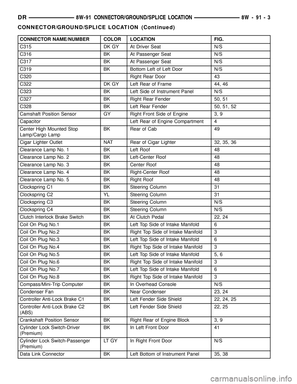
CONNECTOR NAME/NUMBER COLOR LOCATION FIG.
C315 DK GY At Driver Seat N/S
C316 BK At Passenger Seat N/S
C317 BK At Passenger Seat N/S
C319 BK Bottom Left of Left Door N/S
C320 Right Rear Door 43
C322 DK GY Left Rear of Frame 44, 46
C323 BK Left Side of Instrument Panel N/S
C327 BK Right Rear Fender 50, 51
C328 BK Left Rear Fender 50, 51, 52
Camshaft Position Sensor GY Right Front Side of Engine 3, 9
Capacitor Left Rear of Engine Compartment 4
Center High Mounted Stop
Lamp/Cargo LampBK Rear of Cab 49
Cigar Lighter Outlet NAT Rear of Cigar Lighter 32, 35, 36
Clearance Lamp No. 1 BK Left Roof 48
Clearance Lamp No. 2 BK Left-Center Roof 48
Clearance Lamp No. 3 BK Center Roof 48
Clearance Lamp No. 4 BK Right-Center Roof 48
Clearance Lamp No. 5 BK Right Roof 48
Clockspring C1 BK Steering Column 31
Clockspring C2 YL Steering Column 31
Clockspring C3 BK Steering Column N/S
Clockspring C4 BK Steering Column N/S
Clutch Interlock Brake Switch BK At Clutch Pedal 22, 24
Coil On Plug No.1 BK Left Top Side of Intake Manifold 6
Coil On Plug No.2 BK Right Top Side of Intake Manifold 3
Coil On Plug No.3 BK Left Top Side of Intake Manifold 6
Coil On Plug No.4 BK Right Top Side of Intake Manifold 3
Coil On Plug No.5 BK Left Top Side of Intake Manifold 5, 6
Coil On Plug No.6 BK Right Top Side of Intake Manifold 3
Coil On Plug No.7 BK Left Top Side of Intake Manifold 6
Coil On Plug No.8 BK Right Top Side of Intake Manifold 3
Compass/Mini-Trip Computer BK In Overhead Console N/S
Condenser Fan BK Near Condenser 23, 24
Controller Anti-Lock Brake C1 BK Left Fender Side Shield 22, 24, 25
Controller Anti-Lock Brake C2
(ABS)BK Left Fender Side Shield 22, 25
Crankshaft Position Sensor BK Right Rear of Engine Block 3, 9
Cylinder Lock Switch-Driver
(Premium)BK In Left Front Door 41
Cylinder Lock Switch-Passenger
(Premium)LT GY In Right Front Door N/S
Data Link Connector BK Left Bottom of Instrument Panel 35, 38
DR8W-91 CONNECTOR/GROUND/SPLICE LOCATION 8W - 91 - 3
CONNECTOR/GROUND/SPLICE LOCATION (Continued)
Page 1164 of 2627
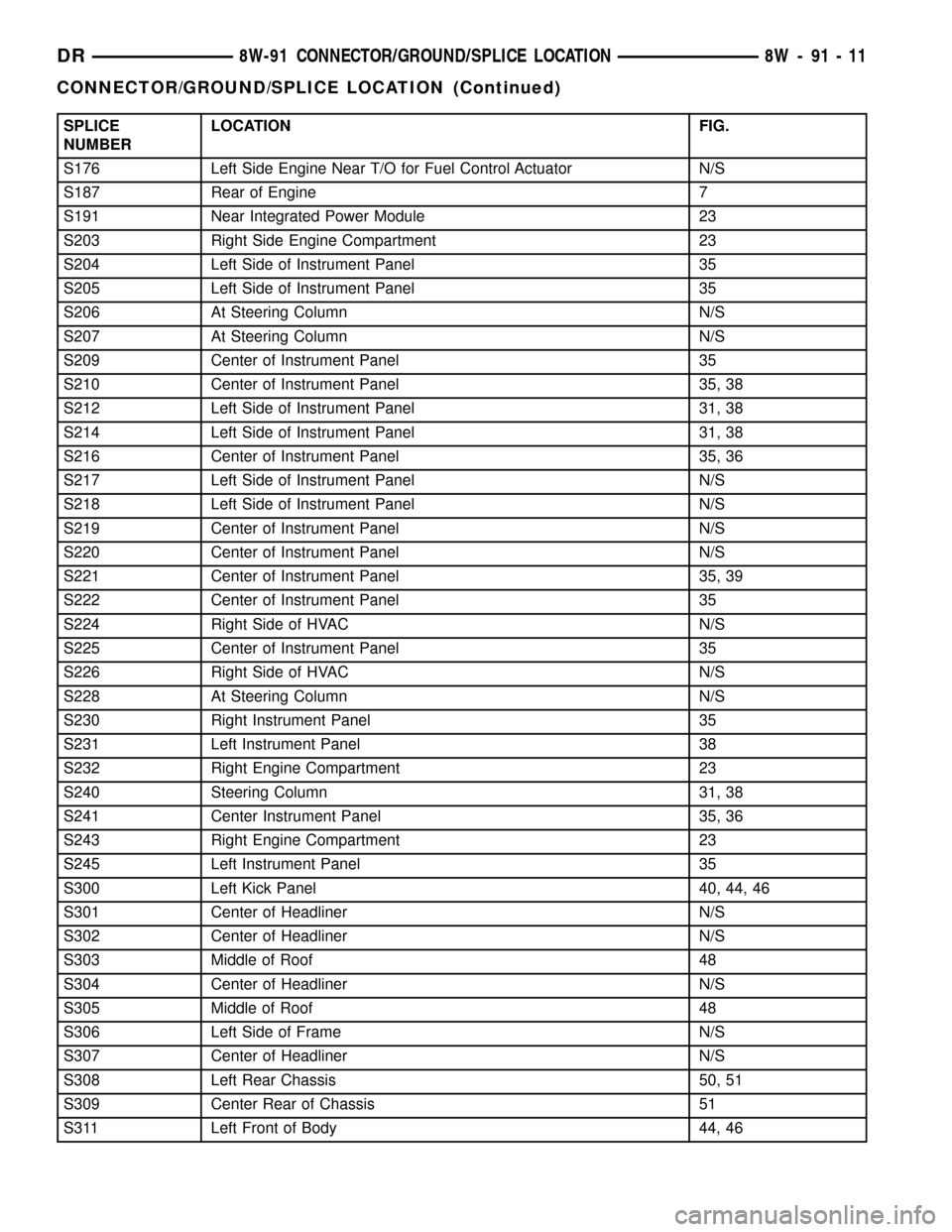
SPLICE
NUMBERLOCATION FIG.
S176 Left Side Engine Near T/O for Fuel Control Actuator N/S
S187 Rear of Engine 7
S191 Near Integrated Power Module 23
S203 Right Side Engine Compartment 23
S204 Left Side of Instrument Panel 35
S205 Left Side of Instrument Panel 35
S206 At Steering Column N/S
S207 At Steering Column N/S
S209 Center of Instrument Panel 35
S210 Center of Instrument Panel 35, 38
S212 Left Side of Instrument Panel 31, 38
S214 Left Side of Instrument Panel 31, 38
S216 Center of Instrument Panel 35, 36
S217 Left Side of Instrument Panel N/S
S218 Left Side of Instrument Panel N/S
S219 Center of Instrument Panel N/S
S220 Center of Instrument Panel N/S
S221 Center of Instrument Panel 35, 39
S222 Center of Instrument Panel 35
S224 Right Side of HVAC N/S
S225 Center of Instrument Panel 35
S226 Right Side of HVAC N/S
S228 At Steering Column N/S
S230 Right Instrument Panel 35
S231 Left Instrument Panel 38
S232 Right Engine Compartment 23
S240 Steering Column 31, 38
S241 Center Instrument Panel 35, 36
S243 Right Engine Compartment 23
S245 Left Instrument Panel 35
S300 Left Kick Panel 40, 44, 46
S301 Center of Headliner N/S
S302 Center of Headliner N/S
S303 Middle of Roof 48
S304 Center of Headliner N/S
S305 Middle of Roof 48
S306 Left Side of Frame N/S
S307 Center of Headliner N/S
S308 Left Rear Chassis 50, 51
S309 Center Rear of Chassis 51
S311 Left Front of Body 44, 46
DR8W-91 CONNECTOR/GROUND/SPLICE LOCATION 8W - 91 - 11
CONNECTOR/GROUND/SPLICE LOCATION (Continued)
Page 1210 of 2627
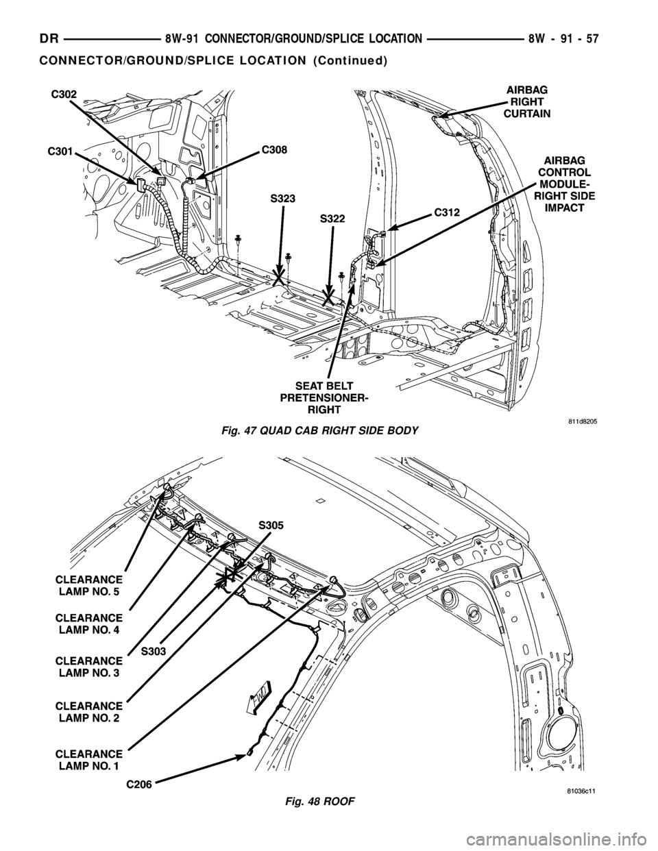
Fig. 47 QUAD CAB RIGHT SIDE BODY
Fig. 48 ROOF
DR8W-91 CONNECTOR/GROUND/SPLICE LOCATION 8W - 91 - 57
CONNECTOR/GROUND/SPLICE LOCATION (Continued)
Page 1487 of 2627
ENGINE BLOCK
STANDARD PROCEDURE
STANDARD PROCEDURE - CYLINDER BLOCK
REFACING
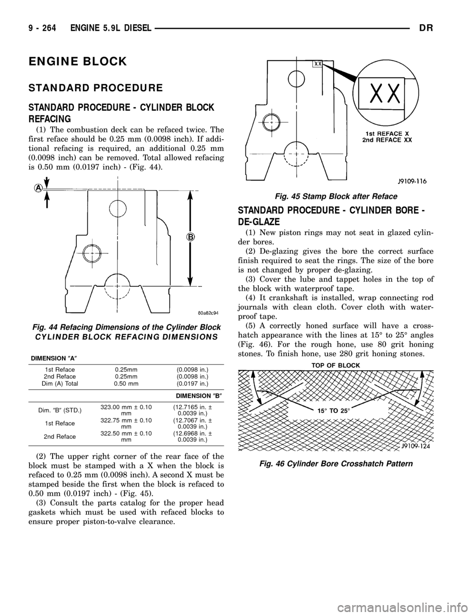
(1) The combustion deck can be refaced twice. The
first reface should be 0.25 mm (0.0098 inch). If addi-
tional refacing is required, an additional 0.25 mm
(0.0098 inch) can be removed. Total allowed refacing
is 0.50 mm (0.0197 inch) - (Fig. 44).
(2) The upper right corner of the rear face of the
block must be stamped with a X when the block is
refaced to 0.25 mm (0.0098 inch). A second X must be
stamped beside the first when the block is refaced to
0.50 mm (0.0197 inch) - (Fig. 45).
(3) Consult the parts catalog for the proper head
gaskets which must be used with refaced blocks to
ensure proper piston-to-valve clearance.
STANDARD PROCEDURE - CYLINDER BORE -
DE-GLAZE
(1) New piston rings may not seat in glazed cylin-
der bores.
(2) De-glazing gives the bore the correct surface
finish required to seat the rings. The size of the bore
is not changed by proper de-glazing.
(3) Cover the lube and tappet holes in the top of
the block with waterproof tape.
(4) It crankshaft is installed, wrap connecting rod
journals with clean cloth. Cover cloth with water-
proof tape.
(5) A correctly honed surface will have a cross-
hatch appearance with the lines at 15É to 25É angles
(Fig. 46). For the rough hone, use 80 grit honing
stones. To finish hone, use 280 grit honing stones.
Fig. 44 Refacing Dimensions of the Cylinder Block
CYLINDER BLOCK REFACING DIMENSIONS
DIMENSION(A(
1st Reface 0.25mm (0.0098 in.)
2nd Reface 0.25mm (0.0098 in.)
Dim (A) Total 0.50 mm (0.0197 in.)
DIMENSION(B(
Dim.9B9(STD.)323.00 mm 0.10
mm(12.7165 in.
0.0039 in.)
1st Reface322.75 mm 0.10
mm(12.7067 in.
0.0039 in.)
2nd Reface322.50 mm 0.10
mm(12.6968 in.
0.0039 in.)
Fig. 45 Stamp Block after Reface
Fig. 46 Cylinder Bore Crosshatch Pattern
9 - 264 ENGINE 5.9L DIESELDR
Page 2314 of 2627
ADJUSTMENTS
ADJUSTMENT
NOTE: For vehicles with four doors, it is recom-
mended that you adjust the rear door before adjust-
ing the front door. (Refer to 23 - BODY/DOORS -
REAR/DOOR - ADJUSTMENTS)
²Door adjustment measurements should be
taken from stationary or welded body panels like
the roof, rocker or quarter panels.
²During adjustment procedures, it is recom-
mended that all the hinge fasteners be loosened
except for the upper most fasteners. Adjustments
can be made using the upper bolts to hold the door
with final torque of the fasteners occurring after
correct door positioning is achieved.
²A suitable body sealant should be used when
removing or moving the hinges.
FORE/AFT
NOTE: Fore/aft (lateral) door adjustment is done by
loosening the hinge to the hinge pillar fasteners
one hinge at a time and moving the door to the cor-
rect position.
(1) Support the door with a suitable lifting device.
(2)
Loosen the hinge to hinge pillar fasteners. (Refer
to 23 - BODY/DOOR - FRONT/HINGE - REMOVAL)
(3) Adjust the door to the correct position. (Refer
to 23 - BODY/BODY STRUCTURE/GAP AND
FLUSH - SPECIFICATIONS)(4) Tighten the hinge pillar fasteners to 28 N´m
(21 ft. lbs.).
UP/DOWN
NOTE: Up/down door adjustment is done by loosen-
ing either the hinge to the hinge pillar fasteners or
the hinge to door fasteners and moving the door to
the correct position.
NOTE: When adjustment of the door requires the
loosening of the door to hinge fasteners, it will be
necessary to separate the epoxy bonded washers
with a chisel or other suitable tool.
NOTE: When the up/down adjustments are done
correctly, the top of the door is positioned over
flush to the roof. (Refer to 23 - BODY/BODY STRUC-
TURE/GAP AND FLUSH - SPECIFICATIONS)
(1) Support the door with a suitable lifting device.
(2) Loosen the latch striker bolts. (Refer to 23 -
BODY/DOOR - FRONT/LATCH STRIKER -
REMOVAL)
(3) Loosen the hinge to door fasteners (Refer to 23
- BODY/DOOR - FRONT/DOOR - REMOVAL) or
loosen the hinge to hinge pillar fasteners (Refer to 23
- BODY/DOOR - FRONT/HINGE - REMOVAL).
(4) Adjust the door to the correct position. (Refer
to 23 - BODY/BODY STRUCTURE/GAP AND
FLUSH - SPECIFICATIONS)
(5) Tighten the hinge pillar fasteners or the door
to hinges fasteners to 28 N´m (21 ft. lbs.).
(6) Tighten the latch striker bolts. (Refer to 23 -
BODY/DOOR - FRONT/LATCH STRIKER - INSTAL-
LATION)
IN/OUT
NOTE: In/out door adjustment is done by loosening
the hinge to door fasteners one hinge at a time and
moving the door to the correct position.
NOTE: When adjustment of the door requires the
loosening of the door to hinge fasteners, it will be
necessary to separate the epoxy bonded washers
with a chisel or other suitable tool.
(1) Support the door with a suitable lifting device.
(2) Loosen the latch striker bolts. (Refer to 23 -
BODY/DOOR - FRONT/LATCH STRIKER -
REMOVAL)
(3) Loosen the hinge to door fasteners. (Refer to 23
- BODY/DOOR - FRONT/DOOR - REMOVAL)
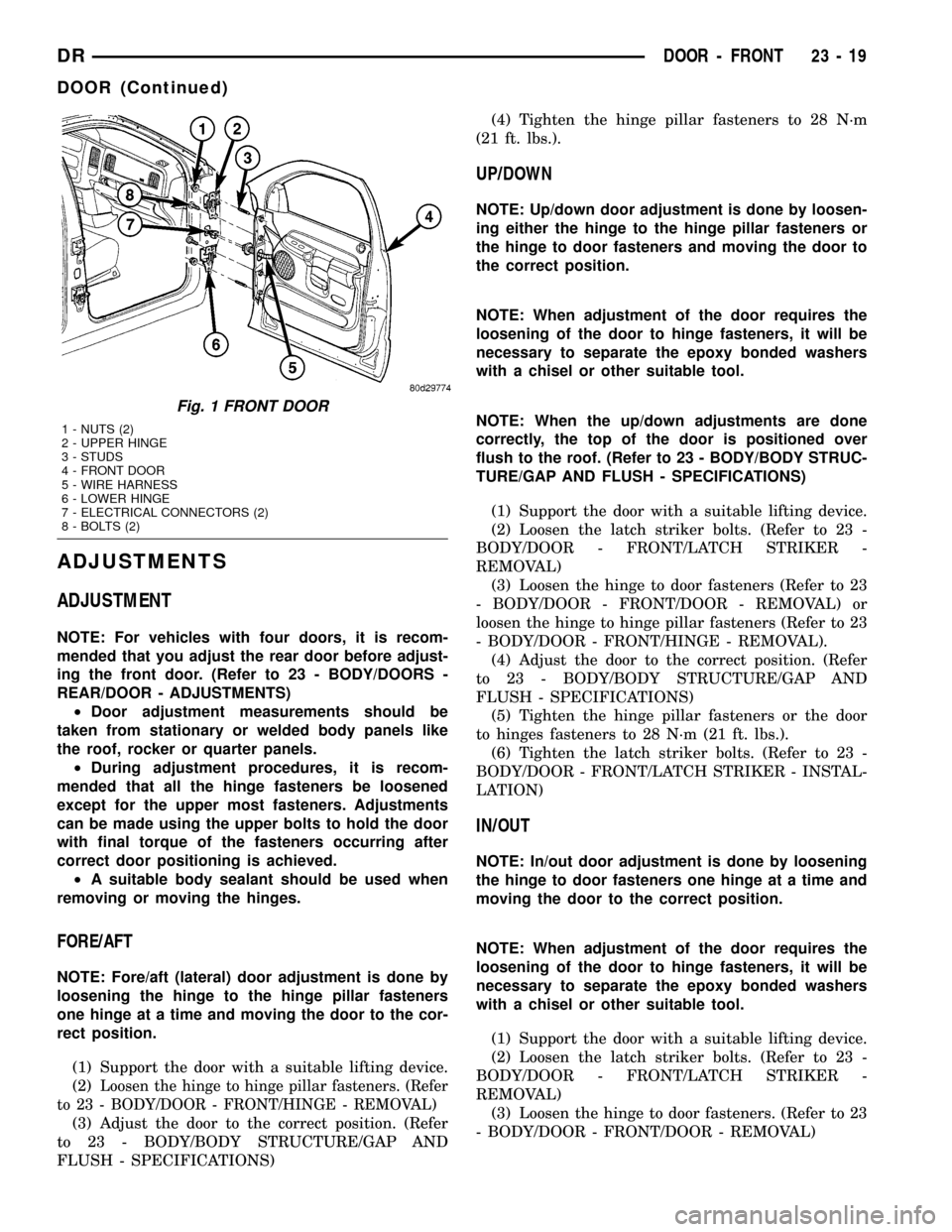
Fig. 1 FRONT DOOR
1 - NUTS (2)
2 - UPPER HINGE
3 - STUDS
4 - FRONT DOOR
5 - WIRE HARNESS
6 - LOWER HINGE
7 - ELECTRICAL CONNECTORS (2)
8 - BOLTS (2)
DRDOOR - FRONT 23 - 19
DOOR (Continued)
Page 2323 of 2627
DOORS - REAR
TABLE OF CONTENTS
page page
DOOR
REMOVAL.............................28
INSTALLATION.........................28
ADJUSTMENTS
ADJUSTMENT........................28
DOOR GLASS
REMOVAL.............................30
INSTALLATION.........................30
EXTERIOR HANDLE
REMOVAL.............................30
INSTALLATION.........................30
GLASS RUN CHANNEL
REMOVAL.............................30
INSTALLATION.........................31
HINGE
REMOVAL.............................31
INSTALLATION.........................31
INSIDE HANDLE ACTUATOR
REMOVAL.............................31
INSTALLATION.........................32
LATCH
REMOVAL.............................32INSTALLATION.........................32
ADJUSTMENTS
ADJUSTMENT........................33
LATCH STRIKER
REMOVAL.............................33
INSTALLATION.........................33
ADJUSTMENTS
ADJUSTMENT........................33
TRIM PANEL
REMOVAL.............................33
INSTALLATION.........................33
WATERDAM
REMOVAL.............................34
INSTALLATION.........................34
WINDOW REGULATOR - POWER
REMOVAL.............................34
INSTALLATION.........................34
WINDOW REGULATOR - MANUAL
REMOVAL.............................35
INSTALLATION.........................35
DOOR
REMOVAL
(1) Disconnect the door wire harness electrical con-
nector at the b-pillar. (Fig. 1)
(2) Using a grease pencil or equivalent, mark the
outline of the door hinges on the door to aid in instal-
lation.
(3) Support the door with a suitable lifting device.
NOTE: The epoxy bonded washers should not be
seperated from the hinge. If the washers are
removed the door may have to be re-adjusted.
(4) Remove the nuts and bolts attaching the door
hinges to the door.
INSTALLATION
(1) Support the door with a suitable lifting device
and install the door onto the hinges.
(2) Install the bolts, nuts and washers, if there
were removed previously, and tighten to 28 N´m (21
ft. lbs.).
(3) Connect the electrical connector.(4) Adjust the door as necessary. (Refer to 23 -
BODY/DOORS - REAR/DOOR - ADJUSTMENTS)
ADJUSTMENTS
ADJUSTMENT
NOTE: For vehicles equipped with four doors, it is
recommended that you adjust the rear door before
adjusting the front door.
²Door adjustment measurements should be
taken from stationary or welded body panels like
the roof, rocker or quarter panels.
²During adjustment procedures, it is recom-
mended that all the hinge fasteners be loosened
except for the upper most fasteners. Adjustments
can be made using the upper fasteners to hold the
door with final torque of the fasteners occurring
after correct door positioning is achieved.
23 - 28 DOORS - REARDR