1998 DODGE RAM 1500 checking oil
[x] Cancel search: checking oilPage 1375 of 2627
DIAGNOSIS AND TESTING
DIAGNOSIS AND TESTING - CHECKING
ENGINE OIL PRESSURE
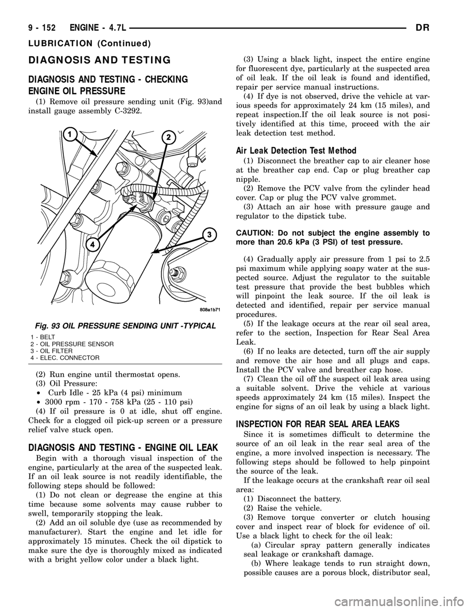
(1) Remove oil pressure sending unit (Fig. 93)and
install gauge assembly C-3292.
(2) Run engine until thermostat opens.
(3) Oil Pressure:
²Curb Idle - 25 kPa (4 psi) minimum
²3000 rpm - 170 - 758 kPa (25 - 110 psi)
(4) If oil pressure is 0 at idle, shut off engine.
Check for a clogged oil pick-up screen or a pressure
relief valve stuck open.
DIAGNOSIS AND TESTING - ENGINE OIL LEAK
Begin with a thorough visual inspection of the
engine, particularly at the area of the suspected leak.
If an oil leak source is not readily identifiable, the
following steps should be followed:
(1) Do not clean or degrease the engine at this
time because some solvents may cause rubber to
swell, temporarily stopping the leak.
(2) Add an oil soluble dye (use as recommended by
manufacturer). Start the engine and let idle for
approximately 15 minutes. Check the oil dipstick to
make sure the dye is thoroughly mixed as indicated
with a bright yellow color under a black light.(3) Using a black light, inspect the entire engine
for fluorescent dye, particularly at the suspected area
of oil leak. If the oil leak is found and identified,
repair per service manual instructions.
(4) If dye is not observed, drive the vehicle at var-
ious speeds for approximately 24 km (15 miles), and
repeat inspection.If the oil leak source is not posi-
tively identified at this time, proceed with the air
leak detection test method.
Air Leak Detection Test Method
(1) Disconnect the breather cap to air cleaner hose
at the breather cap end. Cap or plug breather cap
nipple.
(2) Remove the PCV valve from the cylinder head
cover. Cap or plug the PCV valve grommet.
(3) Attach an air hose with pressure gauge and
regulator to the dipstick tube.
CAUTION: Do not subject the engine assembly to
more than 20.6 kPa (3 PSI) of test pressure.
(4) Gradually apply air pressure from 1 psi to 2.5
psi maximum while applying soapy water at the sus-
pected source. Adjust the regulator to the suitable
test pressure that provide the best bubbles which
will pinpoint the leak source. If the oil leak is
detected and identified, repair per service manual
procedures.
(5) If the leakage occurs at the rear oil seal area,
refer to the section, Inspection for Rear Seal Area
Leak.
(6) If no leaks are detected, turn off the air supply
and remove the air hose and all plugs and caps.
Install the PCV valve and breather cap hose.
(7) Clean the oil off the suspect oil leak area using
a suitable solvent. Drive the vehicle at various
speeds approximately 24 km (15 miles). Inspect the
engine for signs of an oil leak by using a black light.
INSPECTION FOR REAR SEAL AREA LEAKS
Since it is sometimes difficult to determine the
source of an oil leak in the rear seal area of the
engine, a more involved inspection is necessary. The
following steps should be followed to help pinpoint
the source of the leak.
If the leakage occurs at the crankshaft rear oil seal
area:
(1) Disconnect the battery.
(2) Raise the vehicle.
(3) Remove torque converter or clutch housing
cover and inspect rear of block for evidence of oil.
Use a black light to check for the oil leak:
(a) Circular spray pattern generally indicates
seal leakage or crankshaft damage.
(b) Where leakage tends to run straight down,
possible causes are a porous block, distributor seal,
Fig. 93 OIL PRESSURE SENDING UNIT -TYPICAL
1 - BELT
2 - OIL PRESSURE SENSOR
3 - OIL FILTER
4 - ELEC. CONNECTOR
9 - 152 ENGINE - 4.7LDR
LUBRICATION (Continued)
Page 1377 of 2627
OIL LEVEL INDICATOR (DIPSTICK)
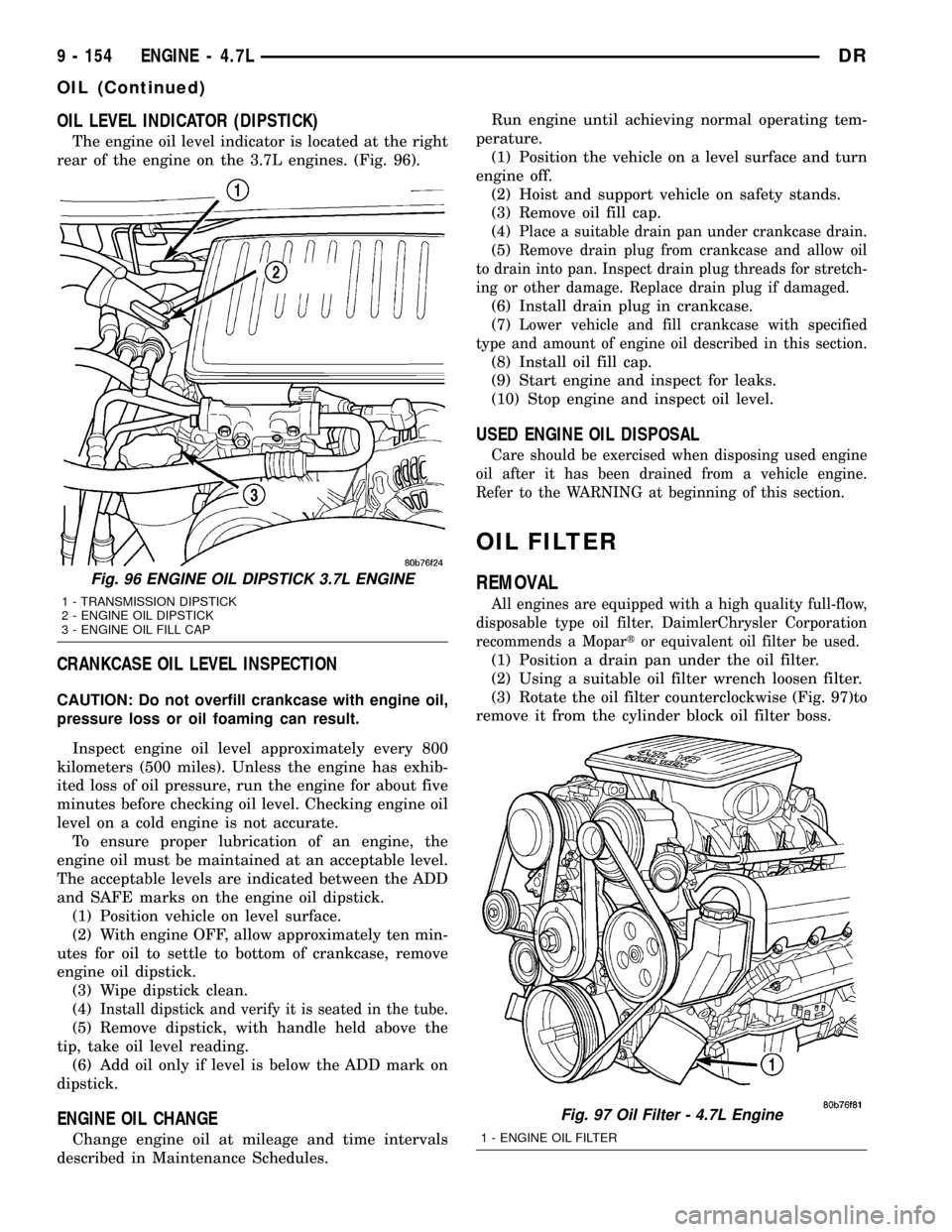
The engine oil level indicator is located at the right
rear of the engine on the 3.7L engines. (Fig. 96).
CRANKCASE OIL LEVEL INSPECTION
CAUTION: Do not overfill crankcase with engine oil,
pressure loss or oil foaming can result.
Inspect engine oil level approximately every 800
kilometers (500 miles). Unless the engine has exhib-
ited loss of oil pressure, run the engine for about five
minutes before checking oil level. Checking engine oil
level on a cold engine is not accurate.
To ensure proper lubrication of an engine, the
engine oil must be maintained at an acceptable level.
The acceptable levels are indicated between the ADD
and SAFE marks on the engine oil dipstick.
(1) Position vehicle on level surface.
(2) With engine OFF, allow approximately ten min-
utes for oil to settle to bottom of crankcase, remove
engine oil dipstick.
(3) Wipe dipstick clean.
(4)
Install dipstick and verify it is seated in the tube.
(5) Remove dipstick, with handle held above the
tip, take oil level reading.
(6) Add oil only if level is below the ADD mark on
dipstick.
ENGINE OIL CHANGE
Change engine oil at mileage and time intervals
described in Maintenance Schedules.Run engine until achieving normal operating tem-
perature.
(1) Position the vehicle on a level surface and turn
engine off.
(2) Hoist and support vehicle on safety stands.
(3) Remove oil fill cap.
(4)
Place a suitable drain pan under crankcase drain.
(5)Remove drain plug from crankcase and allow oil
to drain into pan. Inspect drain plug threads for stretch-
ing or other damage. Replace drain plug if damaged.
(6) Install drain plug in crankcase.
(7)
Lower vehicle and fill crankcase with specified
type and amount of engine oil described in this section.
(8) Install oil fill cap.
(9) Start engine and inspect for leaks.
(10) Stop engine and inspect oil level.
USED ENGINE OIL DISPOSAL
Care should be exercised when disposing used engine
oil after it has been drained from a vehicle engine.
Refer to the WARNING at beginning of this section.
OIL FILTER
REMOVAL
All engines are equipped with a high quality full-flow,
disposable type oil filter. DaimlerChrysler Corporation
recommends a Mopartor equivalent oil filter be used.
(1) Position a drain pan under the oil filter.
(2) Using a suitable oil filter wrench loosen filter.
(3) Rotate the oil filter counterclockwise (Fig. 97)to
remove it from the cylinder block oil filter boss.
Fig. 96 ENGINE OIL DIPSTICK 3.7L ENGINE
1 - TRANSMISSION DIPSTICK
2 - ENGINE OIL DIPSTICK
3 - ENGINE OIL FILL CAP
Fig. 97 Oil Filter - 4.7L Engine
1 - ENGINE OIL FILTER
9 - 154 ENGINE - 4.7LDR
OIL (Continued)
Page 1380 of 2627
DISASSEMBLY
(1) Remove oil pump cover screws and lift off cover
plate.
(2) Remove pump inner and outer rotors.
NOTE: Once the oil pressure relief valve, cup plug,
and pin are removed, the pump assembly must be
replaced.
(3) If it is necessary to remove the pressure relief
valve, drive the roll pin from pump housing and
remove cup plug, spring and valve.
CLEANING
(1) Wash all parts in a suitable solvent.
INSPECTION
CAUTION: Oil pump pressure relief valve and
spring should not be removed from the oil pump. If
these components are disassembled and or
removed from the pump the entire oil pump assem-
bly must be replaced.
(1) Clean all parts thoroughly. Mating surface of
the oil pump housing should be smooth. If the pump
cover is scratched or grooved the oil pump assembly
should be replaced.
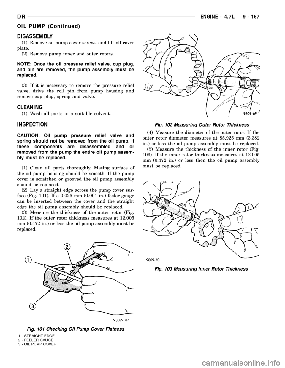
(2) Lay a straight edge across the pump cover sur-
face (Fig. 101). If a 0.025 mm (0.001 in.) feeler gauge
can be inserted between the cover and the straight
edge the oil pump assembly should be replaced.
(3) Measure the thickness of the outer rotor (Fig.
102). If the outer rotor thickness measures at 12.005
mm (0.472 in.) or less the oil pump assembly must be
replaced.(4) Measure the diameter of the outer rotor. If the
outer rotor diameter measures at 85.925 mm (3.382
in.) or less the oil pump assembly must be replaced.
(5) Measure the thickness of the inner rotor (Fig.
103). If the inner rotor thickness measures at 12.005
mm (0.472 in.) or less then the oil pump assembly
must be replaced.
Fig. 101 Checking Oil Pump Cover Flatness
1 - STRAIGHT EDGE
2 - FEELER GAUGE
3 - OIL PUMP COVER
Fig. 102 Measuring Outer Rotor Thickness
Fig. 103 Measuring Inner Rotor Thickness
DRENGINE - 4.7L 9 - 157
OIL PUMP (Continued)
Page 1404 of 2627
STANDARD PROCEDUREÐPISTON FITTING . 211
REMOVAL............................212
CLEANING...........................212
INSPECTION.........................213
INSTALLATION........................213
PISTON RINGS
STANDARD PROCEDURE - PISTON RING
FITTING............................213
VIBRATION DAMPER
REMOVAL............................215
INSTALLATION........................215
STRUCTURAL COVER
DESCRIPTION........................216
OPERATION..........................216
REMOVAL............................216
INSTALLATION........................216
FRONT MOUNT
REMOVAL............................217
INSTALLATION........................218
REAR MOUNT
REMOVAL............................220
INSTALLATION........................220
LUBRICATION
DESCRIPTION........................220
DIAGNOSIS AND TESTING
DIAGNOSIS AND TESTING - CHECKING
ENGINE OIL PRESSURE...............220
DIAGNOSIS AND TESTING - ENGINE OIL
LEAK..............................220
OIL
STANDARD PROCEDURE - ENGINE OIL
SERVICE...........................222
OIL FILTER
REMOVAL............................223INSTALLATION........................223
OIL PAN
REMOVAL............................224
INSTALLATION........................224
OIL PUMP
REMOVAL............................224
CLEANING...........................224
INSPECTION.........................224
INSTALLATION........................225
INTAKE MANIFOLD
DESCRIPTION........................225
DIAGNOSIS AND TESTING - INTAKE
MANIFOLD LEAKAGE.................225
REMOVAL............................226
CLEANING...........................226
INSPECTION.........................226
INSTALLATION........................226
EXHAUST MANIFOLD
DESCRIPTION........................226
OPERATION..........................226
REMOVAL............................226
CLEANING...........................226
INSPECTION.........................227
INSTALLATION........................227
TIMING/CHAIN COVER
REMOVAL............................227
INSTALLATION........................227
TIMING/CHAIN AND SPROCKETS
REMOVAL............................228
INSTALLATION........................228
TIMING CHAIN/TENSIONER
DESCRIPTION........................229
OPERATION..........................229
DRENGINE - 5.7L 9 - 181
Page 1443 of 2627
(8) Torque the (3) bolts that attach the front axle
to the left engine bracket to 101 N´m (75 ft. lbs.).
(9) Install the engine oil filter, if removed.
(10) Install the front crossmember(Refer to 13 -
FRAME & BUMPERS/FRAME/FRONT CROSS-
MEMBER - INSTALLATION).
(11) Install the skid plate.
(12) Lower the vehicle.
(13) Reconnect the negative battery cable.
REAR MOUNT
REMOVAL
(1) Raise the vehicle on a hoist.
(2) Using a suitable jack, support transmission.
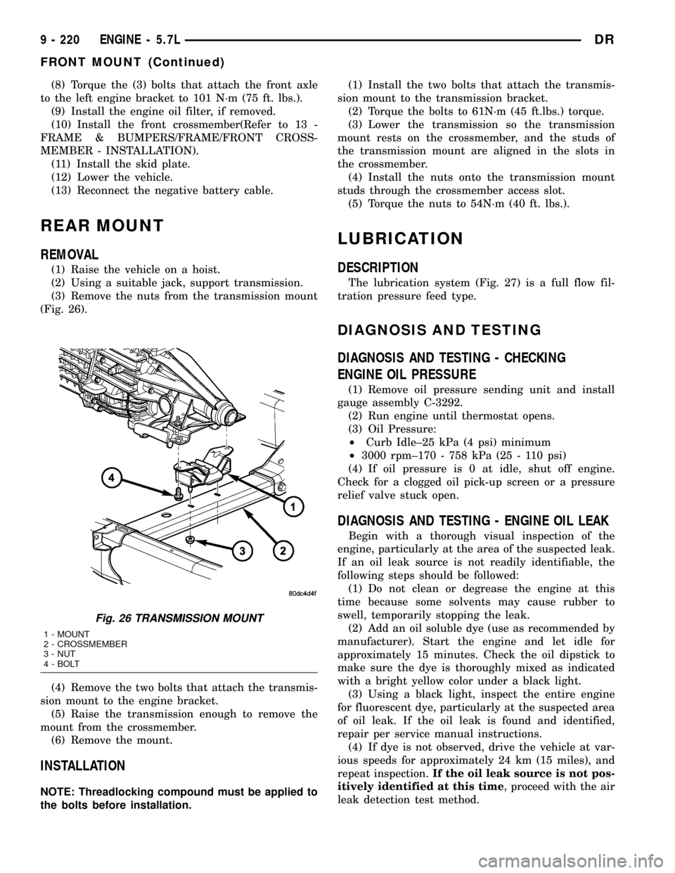
(3) Remove the nuts from the transmission mount
(Fig. 26).
(4) Remove the two bolts that attach the transmis-
sion mount to the engine bracket.
(5) Raise the transmission enough to remove the
mount from the crossmember.
(6) Remove the mount.
INSTALLATION
NOTE: Threadlocking compound must be applied to
the bolts before installation.(1) Install the two bolts that attach the transmis-
sion mount to the transmission bracket.
(2) Torque the bolts to 61N´m (45 ft.lbs.) torque.
(3) Lower the transmission so the transmission
mount rests on the crossmember, and the studs of
the transmission mount are aligned in the slots in
the crossmember.
(4) Install the nuts onto the transmission mount
studs through the crossmember access slot.
(5) Torque the nuts to 54N´m (40 ft. lbs.).
LUBRICATION
DESCRIPTION
The lubrication system (Fig. 27) is a full flow fil-
tration pressure feed type.
DIAGNOSIS AND TESTING
DIAGNOSIS AND TESTING - CHECKING
ENGINE OIL PRESSURE
(1) Remove oil pressure sending unit and install
gauge assembly C-3292.
(2) Run engine until thermostat opens.
(3) Oil Pressure:
²Curb Idle±25 kPa (4 psi) minimum
²3000 rpm±170 - 758 kPa (25 - 110 psi)
(4) If oil pressure is 0 at idle, shut off engine.
Check for a clogged oil pick-up screen or a pressure
relief valve stuck open.
DIAGNOSIS AND TESTING - ENGINE OIL LEAK
Begin with a thorough visual inspection of the
engine, particularly at the area of the suspected leak.
If an oil leak source is not readily identifiable, the
following steps should be followed:
(1) Do not clean or degrease the engine at this
time because some solvents may cause rubber to
swell, temporarily stopping the leak.
(2) Add an oil soluble dye (use as recommended by
manufacturer). Start the engine and let idle for
approximately 15 minutes. Check the oil dipstick to
make sure the dye is thoroughly mixed as indicated
with a bright yellow color under a black light.
(3) Using a black light, inspect the entire engine
for fluorescent dye, particularly at the suspected area
of oil leak. If the oil leak is found and identified,
repair per service manual instructions.
(4) If dye is not observed, drive the vehicle at var-
ious speeds for approximately 24 km (15 miles), and
repeat inspection.If the oil leak source is not pos-
itively identified at this time, proceed with the air
leak detection test method.
Fig. 26 TRANSMISSION MOUNT
1 - MOUNT
2 - CROSSMEMBER
3 - NUT
4 - BOLT
9 - 220 ENGINE - 5.7LDR
FRONT MOUNT (Continued)
Page 1446 of 2627
minutes before checking oil level. Checking engine oil
level on a cold engine is not accurate.
To ensure proper lubrication of an engine, the
engine oil must be maintained at an acceptable level.
The acceptable levels are indicated between the ADD
and SAFE marks on the engine oil dipstick.
(1) Position vehicle on level surface.
(2) With engine OFF, allow approximately five
minutes for oil to settle to bottom of crankcase,
remove engine oil dipstick.
(3) Wipe dipstick clean.
(4) Install dipstick and verify it is seated in the
tube.
(5) Remove dipstick, with handle held above the
tip, take oil level reading.
(6) Add oil only if level is below the ADD mark on
dipstick.
ENGINE OIL CHANGE
Change engine oil at mileage and time intervals
described in Maintenance Schedules(Refer to LUBRI-
CATION & MAINTENANCE/MAINTENANCE
SCHEDULES - DESCRIPTION).
Run engine until achieving normal operating tem-
perature.
(1) Position the vehicle on a level surface and turn
engine off.
(2) Hoist and support vehicle on safety stands.
(3) Remove oil fill cap.
(4) Place a suitable drain pan under crankcase
drain.
(5) Remove drain plug from crankcase and allow
oil to drain into pan. Inspect drain plug threads for
stretching or other damage. Replace drain plug if
damaged.
(6) Install drain plug in crankcase. Torque to 34
N´m ( 25 ft. lbs.).
(7) Lower vehicle and fill crankcase with specified
type and amount of engine oil described in this sec-
tion.
(8) Install oil fill cap.
(9) Start engine and inspect for leaks.
(10) Stop engine and inspect oil level.
USED ENGINE OIL DISPOSAL
Care should be exercised when disposing used
engine oil after it has been drained from a vehicle
engine. Refer to the WARNING at beginning of this
section.
OIL FILTER
REMOVAL
All engines are equipped with a high quality full-
flow, disposable type oil filter. DaimlerChrysler Cor-
poration recommends a Mopartor equivalent oil
filter be used.
(1) Position a drain pan under the oil filter.
(2) Using a suitable oil filter wrench loosen filter.
(3) Rotate the oil filter counterclockwise to remove
it from the cylinder block oil filter boss.
(4) When filter separates from cylinder block oil
filter boss, tip gasket end upward to minimize oil
spill. Remove filter from vehicle.
NOTE: Make sure filter gasket was removed with fil-
ter.
(5) With a wiping cloth, clean the gasket sealing
surface of oil and grime.
INSTALLATION
(1) Lightly lubricate oil filter gasket with engine
oil.
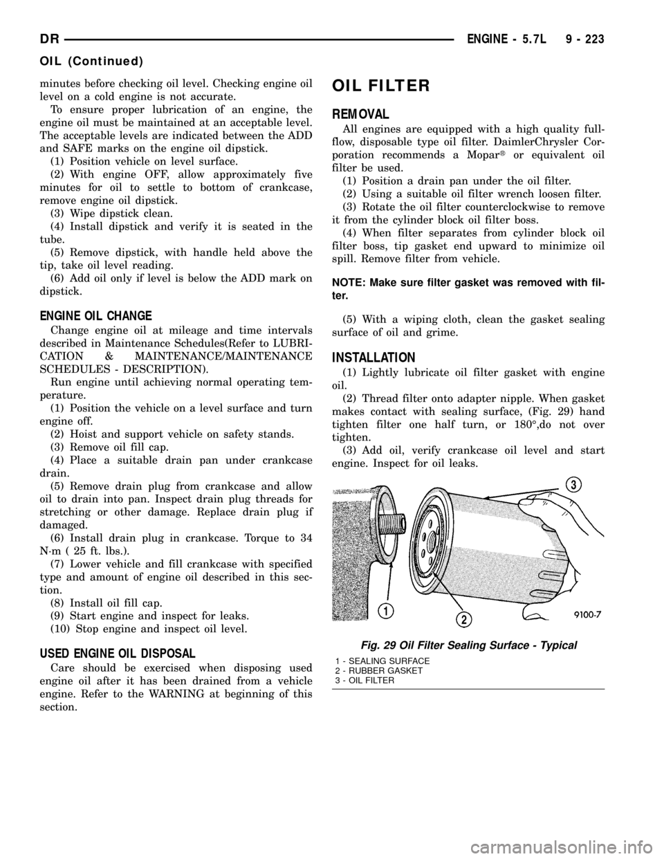
(2) Thread filter onto adapter nipple. When gasket
makes contact with sealing surface, (Fig. 29) hand
tighten filter one half turn, or 180É,do not over
tighten.
(3) Add oil, verify crankcase oil level and start
engine. Inspect for oil leaks.
Fig. 29 Oil Filter Sealing Surface - Typical
1 - SEALING SURFACE
2 - RUBBER GASKET
3 - OIL FILTER
DRENGINE - 5.7L 9 - 223
OIL (Continued)
Page 1694 of 2627
PUMP
TABLE OF CONTENTS
page page
PUMP
DESCRIPTION.........................39
OPERATION...........................40
DIAGNOSIS AND TESTING - PUMP LEAKAGE . 40
STANDARD PROCEDURE
STANDARD PROCEDURE - POWER
STEERING PUMP - INITIAL OPERATION....40
STANDARD PROCEDURE - FLUSHING
POWER STEERING SYSTEM............40
REMOVAL
REMOVAL - GAS......................41
REMOVAL - DIESEL...................41
INSTALLATION
INSTALLATION - GAS..................42
INSTALLATION - DIESEL................42
SPECIFICATIONS
TORQUE CHART......................42
FLUID
DESCRIPTION.........................43
STANDARD PROCEDURE - POWER
STEERING FLUID LEVEL CHECKING......43
FLUID COOLER
REMOVAL.............................43
INSTALLATION.........................43
HOSES - I.F.S.
REMOVAL
REMOVAL - RETURN HOSE - GEAR TO
COOLER............................44
REMOVAL - PRESSURE HOSE...........44
REMOVAL - RETURN HOSE - RESERVOIR
TO COOLER.........................44INSTALLATION
INSTALLATION - RETURN HOSE - GEAR TO
COOLER............................44
INSTALLATION - PRESSURE HOSE.......44
INSTALLATION - RETURN HOSE -
RESERVOIR TO COOLER...............44
HOSES - LINK/COIL
REMOVAL
REMOVAL - RETURN HOSE - GEAR TO
COOLER............................45
REMOVAL - PRESSURE HOSE...........45
REMOVAL - RETURN HOSE - RESERVOIR
TO COOLER.........................45
INSTALLATION
INSTALLATION - RETURN HOSE - GEAR TO
COOLER............................45
INSTALLATION - PRESSURE HOSE.......45
INSTALLATION - RETURN HOSE -
RESERVOIR TO COOLER...............45
POWER STEERING PRESSURE SWITCH
DESCRIPTION.........................46
OPERATION...........................46
REMOVAL - 3.7L & 5.7L..................46
INSTALLATION - 3.7L & 5.7L...............46
PULLEY
REMOVAL.............................47
INSTALLATION.........................47
RESERVOIR
REMOVAL.............................47
INSTALLATION.........................47
PUMP
DESCRIPTION
CAUTION: MOPARTATF+4 is to be used in the
power steering system. No other power steering or
automatic transmission fluid is to be used in the
system. Damage may result to the power steering
pump and system if any other fluid is used, and do
not overfill.The pump is connected to the steering gear via the
pressure hose and the return hose. The pump shaft
has a pressed-on pulley that is belt driven by the
crankshaft pulley.
All vehicles are equipped with a power steering
fluid cooler.
NOTE: Power steering pumps are not interchange-
able with pumps installed on other vehicles.
DRPUMP 19 - 39
Page 1695 of 2627
OPERATION
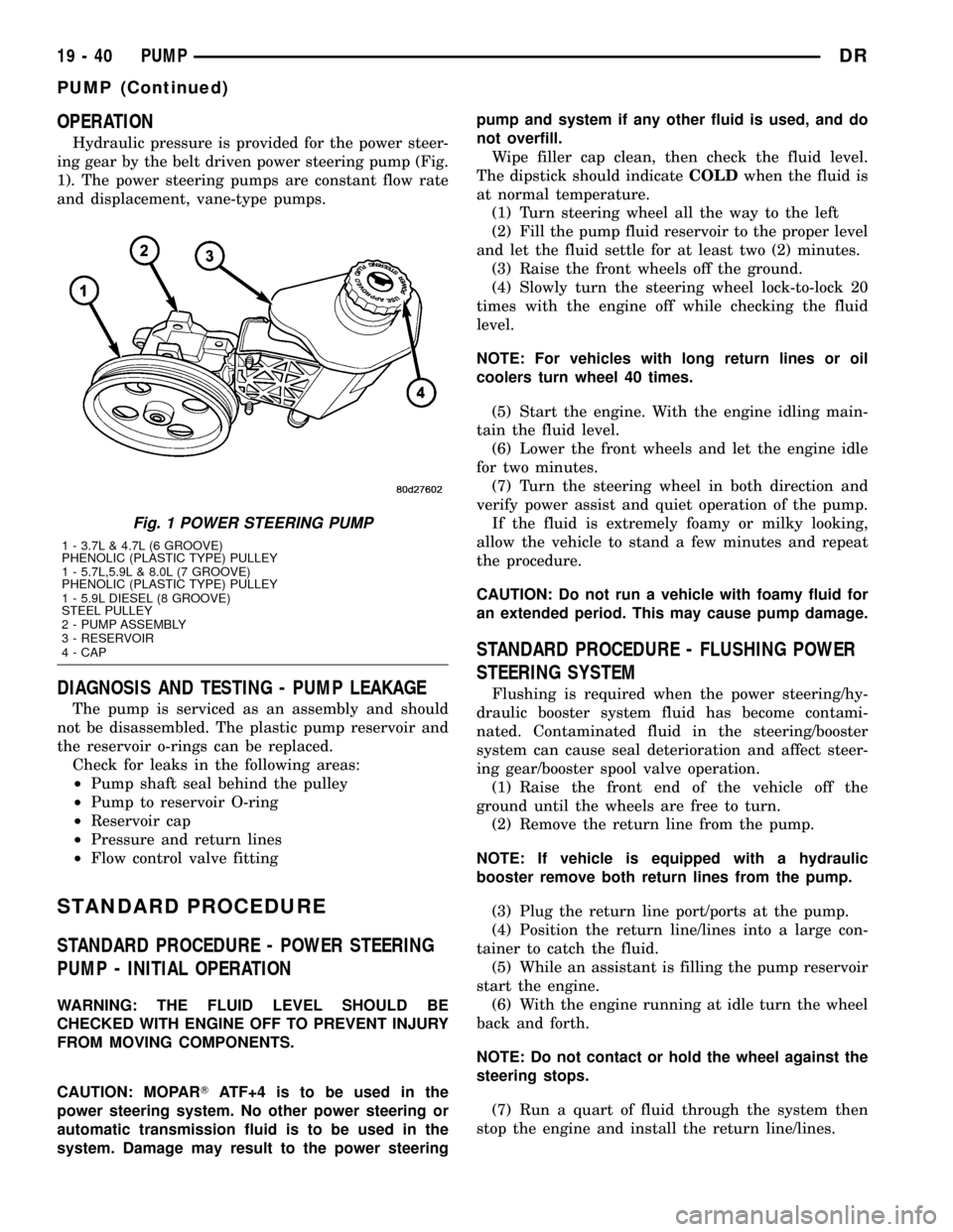
Hydraulic pressure is provided for the power steer-
ing gear by the belt driven power steering pump (Fig.
1). The power steering pumps are constant flow rate
and displacement, vane-type pumps.
DIAGNOSIS AND TESTING - PUMP LEAKAGE
The pump is serviced as an assembly and should
not be disassembled. The plastic pump reservoir and
the reservoir o-rings can be replaced.
Check for leaks in the following areas:
²Pump shaft seal behind the pulley
²Pump to reservoir O-ring
²Reservoir cap
²Pressure and return lines
²Flow control valve fitting
STANDARD PROCEDURE
STANDARD PROCEDURE - POWER STEERING
PUMP - INITIAL OPERATION
WARNING: THE FLUID LEVEL SHOULD BE
CHECKED WITH ENGINE OFF TO PREVENT INJURY
FROM MOVING COMPONENTS.
CAUTION: MOPARTATF+4 is to be used in the
power steering system. No other power steering or
automatic transmission fluid is to be used in the
system. Damage may result to the power steeringpump and system if any other fluid is used, and do
not overfill.
Wipe filler cap clean, then check the fluid level.
The dipstick should indicateCOLDwhen the fluid is
at normal temperature.
(1) Turn steering wheel all the way to the left
(2) Fill the pump fluid reservoir to the proper level
and let the fluid settle for at least two (2) minutes.
(3) Raise the front wheels off the ground.
(4) Slowly turn the steering wheel lock-to-lock 20
times with the engine off while checking the fluid
level.
NOTE: For vehicles with long return lines or oil
coolers turn wheel 40 times.
(5) Start the engine. With the engine idling main-
tain the fluid level.
(6) Lower the front wheels and let the engine idle
for two minutes.
(7) Turn the steering wheel in both direction and
verify power assist and quiet operation of the pump.
If the fluid is extremely foamy or milky looking,
allow the vehicle to stand a few minutes and repeat
the procedure.
CAUTION: Do not run a vehicle with foamy fluid for
an extended period. This may cause pump damage.
STANDARD PROCEDURE - FLUSHING POWER
STEERING SYSTEM
Flushing is required when the power steering/hy-
draulic booster system fluid has become contami-
nated. Contaminated fluid in the steering/booster
system can cause seal deterioration and affect steer-
ing gear/booster spool valve operation.
(1) Raise the front end of the vehicle off the
ground until the wheels are free to turn.
(2) Remove the return line from the pump.
NOTE: If vehicle is equipped with a hydraulic
booster remove both return lines from the pump.
(3) Plug the return line port/ports at the pump.
(4) Position the return line/lines into a large con-
tainer to catch the fluid.
(5) While an assistant is filling the pump reservoir
start the engine.
(6) With the engine running at idle turn the wheel
back and forth.
NOTE: Do not contact or hold the wheel against the
steering stops.
(7) Run a quart of fluid through the system then
stop the engine and install the return line/lines.
Fig. 1 POWER STEERING PUMP
1 - 3.7L & 4.7L (6 GROOVE)
PHENOLIC (PLASTIC TYPE) PULLEY
1 - 5.7L,5.9L & 8.0L (7 GROOVE)
PHENOLIC (PLASTIC TYPE) PULLEY
1 - 5.9L DIESEL (8 GROOVE)
STEEL PULLEY
2 - PUMP ASSEMBLY
3 - RESERVOIR
4 - CAP
19 - 40 PUMPDR
PUMP (Continued)