1998 DODGE RAM 1500 checking oil
[x] Cancel search: checking oilPage 1274 of 2627
(10) Once you have selected the proper insert,
install the insert and cap. Tighten the connecting rod
bolts to 27 N´m (20 ft. lbs.) plus a 90É turn.
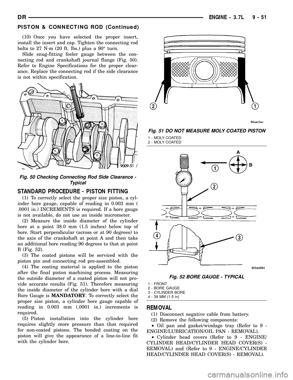
Slide snug-fitting feeler gauge between the con-
necting rod and crankshaft journal flange (Fig. 50).
Refer to Engine Specifications for the proper clear-
ance. Replace the connecting rod if the side clearance
is not within specification.
STANDARD PROCEDURE - PISTON FITTING
(1) To correctly select the proper size piston, a cyl-
inder bore gauge, capable of reading in 0.003 mm (
.0001 in.) INCREMENTS is required. If a bore gauge
is not available, do not use an inside micrometer.
(2) Measure the inside diameter of the cylinder
bore at a point 38.0 mm (1.5 inches) below top of
bore. Start perpendicular (across or at 90 degrees) to
the axis of the crankshaft at point A and then take
an additional bore reading 90 degrees to that at point
B (Fig. 52).
(3) The coated pistons will be serviced with the
piston pin and connecting rod pre-assembled.
(4) The coating material is applied to the piston
after the final piston machining process. Measuring
the outside diameter of a coated piston will not pro-
vide accurate results (Fig. 51). Therefore measuring
the inside diameter of the cylinder bore with a dial
Bore Gauge isMANDATORY. To correctly select the
proper size piston, a cylinder bore gauge capable of
reading in 0.003 mm (.0001 in.) increments is
required.
(5) Piston installation into the cylinder bore
requires slightly more pressure than that required
for non-coated pistons. The bonded coating on the
piston will give the appearance of a line-to-line fit
with the cylinder bore.
REMOVAL
(1) Disconnect negative cable from battery.
(2) Remove the following components:
²Oil pan and gasket/windage tray (Refer to 9 -
ENGINE/LUBRICATION/OIL PAN - REMOVAL).
²Cylinder head covers (Refer to 9 - ENGINE/
CYLINDER HEAD/CYLINDER HEAD COVER(S) -
REMOVAL) and (Refer to 9 - ENGINE/CYLINDER
HEAD/CYLINDER HEAD COVER(S) - REMOVAL).
Fig. 50 Checking Connecting Rod Side Clearance -
Typical
Fig. 51 DO NOT MEASURE MOLY COATED PISTON
1 - MOLY COATED
2 - MOLY COATED
Fig. 52 BORE GAUGE - TYPICAL
1 - FRONT
2 - BORE GAUGE
3 - CYLINDER BORE
4 - 38 MM (1.5 in)
DRENGINE - 3.7L 9 - 51
PISTON & CONNECTING ROD (Continued)
Page 1288 of 2627
DIAGNOSIS AND TESTING - CHECKING
ENGINE OIL PRESSURE
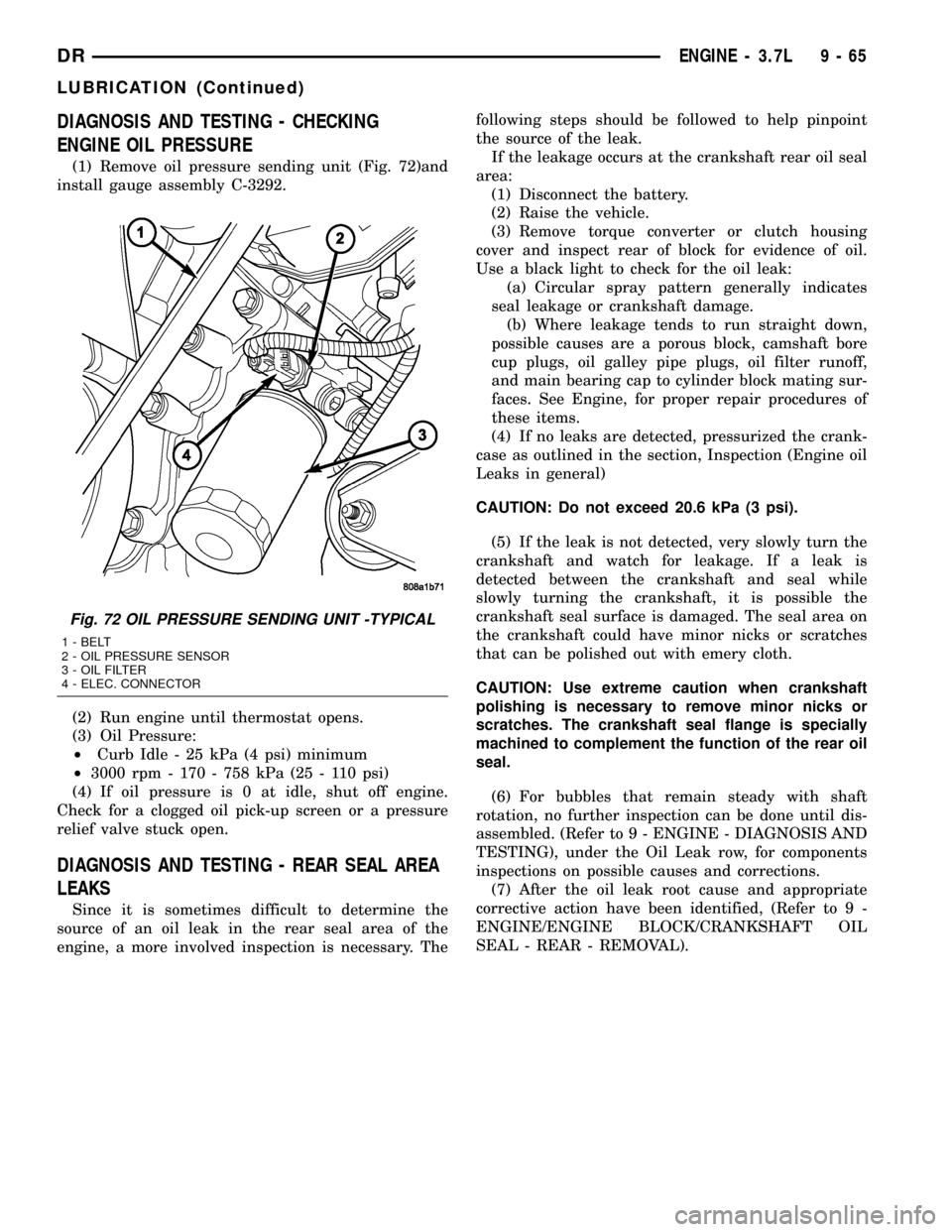
(1) Remove oil pressure sending unit (Fig. 72)and
install gauge assembly C-3292.
(2) Run engine until thermostat opens.
(3) Oil Pressure:
²Curb Idle - 25 kPa (4 psi) minimum
²3000 rpm - 170 - 758 kPa (25 - 110 psi)
(4) If oil pressure is 0 at idle, shut off engine.
Check for a clogged oil pick-up screen or a pressure
relief valve stuck open.
DIAGNOSIS AND TESTING - REAR SEAL AREA
LEAKS
Since it is sometimes difficult to determine the
source of an oil leak in the rear seal area of the
engine, a more involved inspection is necessary. Thefollowing steps should be followed to help pinpoint
the source of the leak.
If the leakage occurs at the crankshaft rear oil seal
area:
(1) Disconnect the battery.
(2) Raise the vehicle.
(3) Remove torque converter or clutch housing
cover and inspect rear of block for evidence of oil.
Use a black light to check for the oil leak:
(a) Circular spray pattern generally indicates
seal leakage or crankshaft damage.
(b) Where leakage tends to run straight down,
possible causes are a porous block, camshaft bore
cup plugs, oil galley pipe plugs, oil filter runoff,
and main bearing cap to cylinder block mating sur-
faces. See Engine, for proper repair procedures of
these items.
(4) If no leaks are detected, pressurized the crank-
case as outlined in the section, Inspection (Engine oil
Leaks in general)
CAUTION: Do not exceed 20.6 kPa (3 psi).
(5) If the leak is not detected, very slowly turn the
crankshaft and watch for leakage. If a leak is
detected between the crankshaft and seal while
slowly turning the crankshaft, it is possible the
crankshaft seal surface is damaged. The seal area on
the crankshaft could have minor nicks or scratches
that can be polished out with emery cloth.
CAUTION: Use extreme caution when crankshaft
polishing is necessary to remove minor nicks or
scratches. The crankshaft seal flange is specially
machined to complement the function of the rear oil
seal.
(6) For bubbles that remain steady with shaft
rotation, no further inspection can be done until dis-
assembled. (Refer to 9 - ENGINE - DIAGNOSIS AND
TESTING), under the Oil Leak row, for components
inspections on possible causes and corrections.
(7) After the oil leak root cause and appropriate
corrective action have been identified, (Refer to 9 -
ENGINE/ENGINE BLOCK/CRANKSHAFT OIL
SEAL - REAR - REMOVAL).
Fig. 72 OIL PRESSURE SENDING UNIT -TYPICAL
1 - BELT
2 - OIL PRESSURE SENSOR
3 - OIL FILTER
4 - ELEC. CONNECTOR
DRENGINE - 3.7L 9 - 65
LUBRICATION (Continued)
Page 1291 of 2627
(3) Remove the timing chains and tensioners
(Refer to 9 - ENGINE/VALVE TIMING/TIMING
BELT/CHAIN AND SPROCKETS - REMOVAL).
(4) Remove the four bolts, primary timing chain
tensioner and the oil pump.
DISASSEMBLY
(1) Remove oil pump cover screws and lift off cover
plate.
(2) Remove pump inner and outer rotors.
NOTE: Once the oil pressure relief valve, cup plug,
and pin are removed, the pump assembly must be
replaced.
(3) If it is necessary to remove the pressure relief
valve, drive the roll pin from pump housing and
remove cup plug, spring and valve.
INSPECTION
CAUTION: Oil pump pressure relief valve and spring
should not be removed from the oil pump. If these com-
ponents are disassembled and or removed from the
pump the entire oil pump assembly must be replaced.
(1) Clean all parts thoroughly. Mating surface of
the oil pump housing should be smooth. If the pump
cover is scratched or grooved the oil pump assembly
should be replaced.
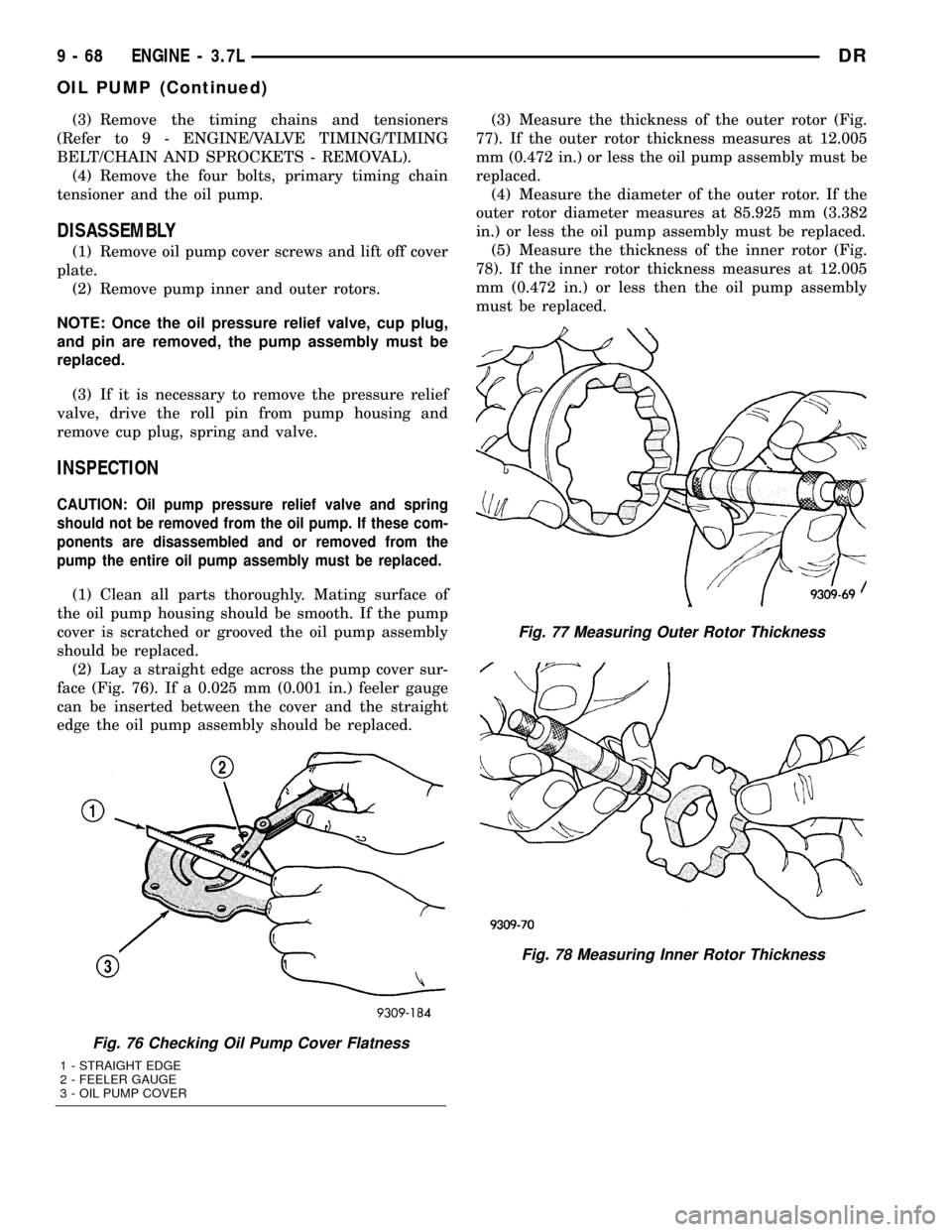
(2) Lay a straight edge across the pump cover sur-
face (Fig. 76). If a 0.025 mm (0.001 in.) feeler gauge
can be inserted between the cover and the straight
edge the oil pump assembly should be replaced.(3) Measure the thickness of the outer rotor (Fig.
77). If the outer rotor thickness measures at 12.005
mm (0.472 in.) or less the oil pump assembly must be
replaced.
(4) Measure the diameter of the outer rotor. If the
outer rotor diameter measures at 85.925 mm (3.382
in.) or less the oil pump assembly must be replaced.
(5) Measure the thickness of the inner rotor (Fig.
78). If the inner rotor thickness measures at 12.005
mm (0.472 in.) or less then the oil pump assembly
must be replaced.
Fig. 76 Checking Oil Pump Cover Flatness
1 - STRAIGHT EDGE
2 - FEELER GAUGE
3 - OIL PUMP COVER
Fig. 77 Measuring Outer Rotor Thickness
Fig. 78 Measuring Inner Rotor Thickness
9 - 68 ENGINE - 3.7LDR
OIL PUMP (Continued)
Page 1295 of 2627
CRANKCASE OIL LEVEL INSPECTION
CAUTION: Do not overfill crankcase with engine oil,
pressure loss or oil foaming can result.
Inspect engine oil level approximately every 800
kilometers (500 miles). Unless the engine has exhib-
ited loss of oil pressure, run the engine for about five
minutes before checking oil level. Checking engine oil
level on a cold engine is not accurate.
To ensure proper lubrication of an engine, the
engine oil must be maintained at an acceptable level.
The acceptable levels are indicated between the ADD
and SAFE marks on the engine oil dipstick.
(1) Position vehicle on level surface.
(2) With engine OFF, allow approximately ten min-
utes for oil to settle to bottom of crankcase, remove
engine oil dipstick.
(3) Wipe dipstick clean.
(4) Install dipstick and verify it is seated in the
tube.
(5) Remove dipstick, with handle held above the
tip, take oil level reading.
(6) Add oil only if level is below the ADD mark on
dipstick.
ENGINE OIL CHANGE
Change engine oil at mileage and time intervals
described in Maintenance Schedules.
Run engine until achieving normal operating tem-
perature.
(1) Position the vehicle on a level surface and turn
engine off.
(2) Hoist and support vehicle on safety stands.
(3) Remove oil fill cap.
(4) Place a suitable drain pan under crankcase
drain.
(5) Remove drain plug from crankcase and allow
oil to drain into pan. Inspect drain plug threads for
stretching or other damage. Replace drain plug if
damaged.
(6) Install drain plug in crankcase.
(7) Lower vehicle and fill crankcase with specified
type and amount of engine oil described in this sec-
tion.
(8) Install oil fill cap.
(9) Start engine and inspect for leaks.
(10) Stop engine and inspect oil level.
USED ENGINE OIL DISPOSAL
Care should be exercised when disposing used
engine oil after it has been drained from a vehicle
engine. Refer to the WARNING at beginning of this
section.
INTAKE MANIFOLD
DESCRIPTION
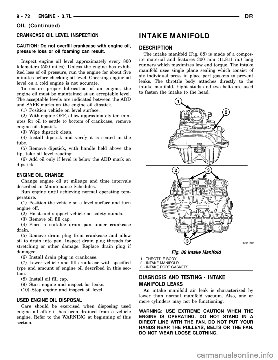
The intake manifold (Fig. 88) is made of a compos-
ite material and features 300 mm (11.811 in.) long
runners which maximizes low end torque. The intake
manifold uses single plane sealing which consist of
six individual press in place port gaskets to prevent
leaks. The throttle body attaches directly to the
intake manifold. Eight studs and two bolts are used
to fasten the intake to the head.
DIAGNOSIS AND TESTING - INTAKE
MANIFOLD LEAKS
An intake manifold air leak is characterized by
lower than normal manifold vacuum. Also, one or
more cylinders may not be functioning.
WARNING: USE EXTREME CAUTION WHEN THE
ENGINE IS OPERATING. DO NOT STAND IN A
DIRECT LINE WITH THE FAN. DO NOT PUT YOUR
HANDS NEAR THE PULLEYS, BELTS OR THE FAN.
DO NOT WEAR LOOSE CLOTHING.
Fig. 88 Intake Manifold
1 - THROTTLE BODY
2 - INTAKE MANIFOLD
3 - INTAKE PORT GASKETS
9 - 72 ENGINE - 3.7LDR
OIL (Continued)
Page 1312 of 2627
CRANKSHAFT OIL SEAL - REAR
DIAGNOSIS AND TESTING - REAR SEAL
AREA LEAKS........................137
REMOVAL............................137
INSTALLATION........................138
FLEX PLATE
REMOVAL............................138
INSTALLATION........................138
PISTON & CONNECTING ROD
DESCRIPTION........................139
STANDARD PROCEDURE - PISTON FITTING . 139
REMOVAL............................139
CLEANING...........................140
INSPECTION.........................140
INSTALLATION........................140
PISTON RINGS
STANDARD PROCEDURE - PISTON RING
FITTING............................142
VIBRATION DAMPER
REMOVAL............................144
INSTALLATION........................144
STRUCTURAL COVER
DESCRIPTION........................145
OPERATION..........................145
REMOVAL............................145
INSTALLATION........................145
FRONT MOUNT
REMOVAL............................146
INSTALLATION........................147
REAR MOUNT
REMOVAL............................149
INSTALLATION........................149
LUBRICATION
DESCRIPTION........................150
OPERATION..........................150
DIAGNOSIS AND TESTING
DIAGNOSIS AND TESTING - CHECKING
ENGINE OIL PRESSURE...............152
DIAGNOSIS AND TESTING - ENGINE OIL
LEAK..............................152
OIL
STANDARD PROCEDURE - ENGINE OIL
SERVICE...........................153
OIL FILTER
REMOVAL............................154
INSTALLATION........................155
OIL PAN
REMOVAL............................155
INSTALLATION........................155OIL PRESSURE SENSOR/SWITCH
DESCRIPTION
DESCRIPTION.......................156
DESCRIPTION.......................156
OPERATION
OPERATION........................156
OPERATION........................156
REMOVAL............................156
INSTALLATION........................156
OIL PUMP
REMOVAL............................156
DISASSEMBLY........................157
CLEANING...........................157
INSPECTION.........................157
ASSEMBLY...........................158
INSTALLATION........................159
INTAKE MANIFOLD
DESCRIPTION........................159
DIAGNOSIS AND TESTINGÐINTAKE
MANIFOLD LEAKAGE.................159
REMOVAL............................159
CLEANING...........................160
INSPECTION.........................160
INSTALLATION........................160
EXHAUST MANIFOLD
DESCRIPTION........................161
REMOVAL............................161
CLEANING...........................163
INSPECTION.........................163
INSTALLATION........................164
VALVE TIMING
DESCRIPTIONÐTIMING DRIVE SYSTEM....166
OPERATION - TIMING DRIVE SYSTEM.....166
STANDARD PROCEDURE
STANDARD PROCEDUREÐMEASURING
TIMING CHAIN WEAR.................167
STANDARD PROCEDURE - ENGINE TIMING
- VERIFICATION.....................167
TIMING BELT / CHAIN COVER(S)
REMOVAL............................170
INSTALLATION........................171
TIMING BELT/CHAIN AND SPROCKETS
REMOVAL............................172
INSPECTION.........................174
INSTALLATION........................176
IDLER SHAFT
REMOVAL............................179
INSTALLATION........................179
DRENGINE - 4.7L 9 - 89
Page 1335 of 2627
INSTALLATION
INSTALLATION - LEFT CYLINDER HEAD
NOTE: The cylinder head bolts are tightened using
a torque plus angle procedure. The bolts must be
examined BEFORE reuse. If the threads are necked
down the bolts should be replaced.
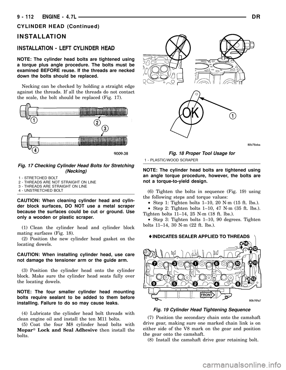
Necking can be checked by holding a straight edge
against the threads. If all the threads do not contact
the scale, the bolt should be replaced (Fig. 17).
CAUTION: When cleaning cylinder head and cylin-
der block surfaces, DO NOT use a metal scraper
because the surfaces could be cut or ground. Use
only a wooden or plastic scraper.
(1) Clean the cylinder head and cylinder block
mating surfaces (Fig. 18).
(2) Position the new cylinder head gasket on the
locating dowels.
CAUTION: When installing cylinder head, use care
not damage the tensioner arm or the guide arm.
(3) Position the cylinder head onto the cylinder
block. Make sure the cylinder head seats fully over
the locating dowels.
NOTE: The four smaller cylinder head mounting
bolts require sealant to be added to them before
installing. Failure to do so may cause leaks.
(4) Lubricate the cylinder head bolt threads with
clean engine oil and install the ten M11 bolts.
(5) Coat the four M8 cylinder head bolts with
MopartLock and Seal Adhesivethen install the
bolts.NOTE: The cylinder head bolts are tightened using
an angle torque procedure, however, the bolts are
not a torque-to-yield design.
(6) Tighten the bolts in sequence (Fig. 19) using
the following steps and torque values:
²Step 1: Tighten bolts 1±10, 20 N´m (15 ft. lbs.).
²Step 2: Tighten bolts 1±10, 47 N´m (35 ft. lbs.).
Tighten bolts 11±14, 25 N´m (18 ft. lbs.).
²Step 3: Tighten bolts 1±10, 90 degrees. Tighten
bolts 11±14, 30 N´m (22 ft. lbs.).
(7) Position the secondary chain onto the camshaft
drive gear, making sure one marked chain link is on
either side of the V8 mark on the gear and position
the gear onto the camshaft.
(8) Install the camshaft drive gear retaining bolt.
Fig. 17 Checking Cylinder Head Bolts for Stretching
(Necking)
1 - STRETCHED BOLT
2 - THREADS ARE NOT STRAIGHT ON LINE
3 - THREADS ARE STRAIGHT ON LINE
4 - UNSTRETCHED BOLT
Fig. 18 Proper Tool Usage for
1 - PLASTIC/WOOD SCRAPER
Fig. 19 Cylinder Head Tightening Sequence
9 - 112 ENGINE - 4.7LDR
CYLINDER HEAD (Continued)
Page 1336 of 2627
(9) Install the left side secondary chain guide
(Refer to 9 - ENGINE/VALVE TIMING/TIMING
BELT/CHAIN AND SPROCKETS - INSTALLA-
TION).
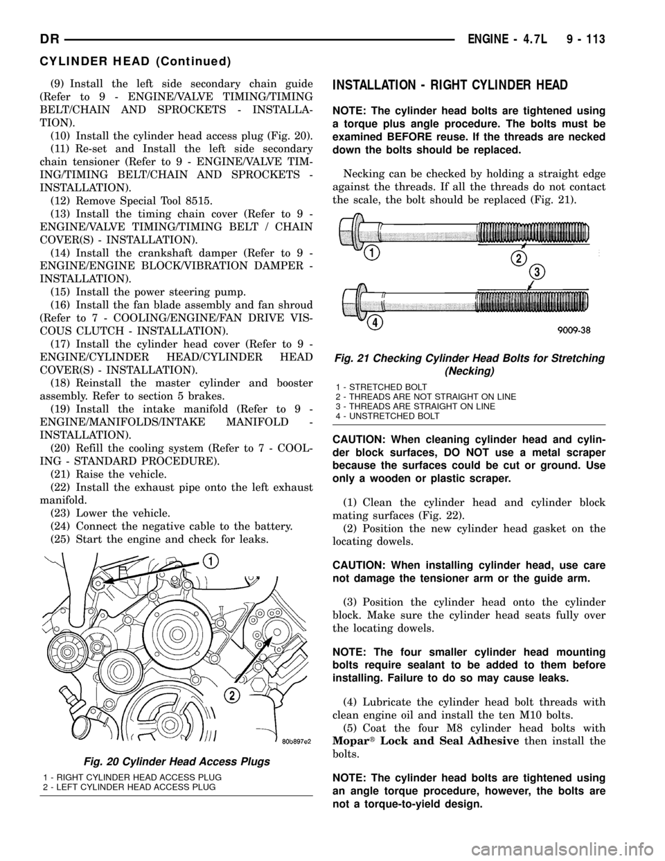
(10) Install the cylinder head access plug (Fig. 20).
(11) Re-set and Install the left side secondary
chain tensioner (Refer to 9 - ENGINE/VALVE TIM-
ING/TIMING BELT/CHAIN AND SPROCKETS -
INSTALLATION).
(12) Remove Special Tool 8515.
(13) Install the timing chain cover (Refer to 9 -
ENGINE/VALVE TIMING/TIMING BELT / CHAIN
COVER(S) - INSTALLATION).
(14) Install the crankshaft damper (Refer to 9 -
ENGINE/ENGINE BLOCK/VIBRATION DAMPER -
INSTALLATION).
(15) Install the power steering pump.
(16) Install the fan blade assembly and fan shroud
(Refer to 7 - COOLING/ENGINE/FAN DRIVE VIS-
COUS CLUTCH - INSTALLATION).
(17) Install the cylinder head cover (Refer to 9 -
ENGINE/CYLINDER HEAD/CYLINDER HEAD
COVER(S) - INSTALLATION).
(18) Reinstall the master cylinder and booster
assembly. Refer to section 5 brakes.
(19) Install the intake manifold (Refer to 9 -
ENGINE/MANIFOLDS/INTAKE MANIFOLD -
INSTALLATION).
(20) Refill the cooling system (Refer to 7 - COOL-
ING - STANDARD PROCEDURE).
(21) Raise the vehicle.
(22) Install the exhaust pipe onto the left exhaust
manifold.
(23) Lower the vehicle.
(24) Connect the negative cable to the battery.
(25) Start the engine and check for leaks.INSTALLATION - RIGHT CYLINDER HEAD
NOTE: The cylinder head bolts are tightened using
a torque plus angle procedure. The bolts must be
examined BEFORE reuse. If the threads are necked
down the bolts should be replaced.
Necking can be checked by holding a straight edge
against the threads. If all the threads do not contact
the scale, the bolt should be replaced (Fig. 21).
CAUTION: When cleaning cylinder head and cylin-
der block surfaces, DO NOT use a metal scraper
because the surfaces could be cut or ground. Use
only a wooden or plastic scraper.
(1) Clean the cylinder head and cylinder block
mating surfaces (Fig. 22).
(2) Position the new cylinder head gasket on the
locating dowels.
CAUTION: When installing cylinder head, use care
not damage the tensioner arm or the guide arm.
(3) Position the cylinder head onto the cylinder
block. Make sure the cylinder head seats fully over
the locating dowels.
NOTE: The four smaller cylinder head mounting
bolts require sealant to be added to them before
installing. Failure to do so may cause leaks.
(4) Lubricate the cylinder head bolt threads with
clean engine oil and install the ten M10 bolts.
(5) Coat the four M8 cylinder head bolts with
MopartLock and Seal Adhesivethen install the
bolts.
NOTE: The cylinder head bolts are tightened using
an angle torque procedure, however, the bolts are
not a torque-to-yield design.
Fig. 20 Cylinder Head Access Plugs
1 - RIGHT CYLINDER HEAD ACCESS PLUG
2 - LEFT CYLINDER HEAD ACCESS PLUG
Fig. 21 Checking Cylinder Head Bolts for Stretching
(Necking)
1 - STRETCHED BOLT
2 - THREADS ARE NOT STRAIGHT ON LINE
3 - THREADS ARE STRAIGHT ON LINE
4 - UNSTRETCHED BOLT
DRENGINE - 4.7L 9 - 113
CYLINDER HEAD (Continued)
Page 1353 of 2627
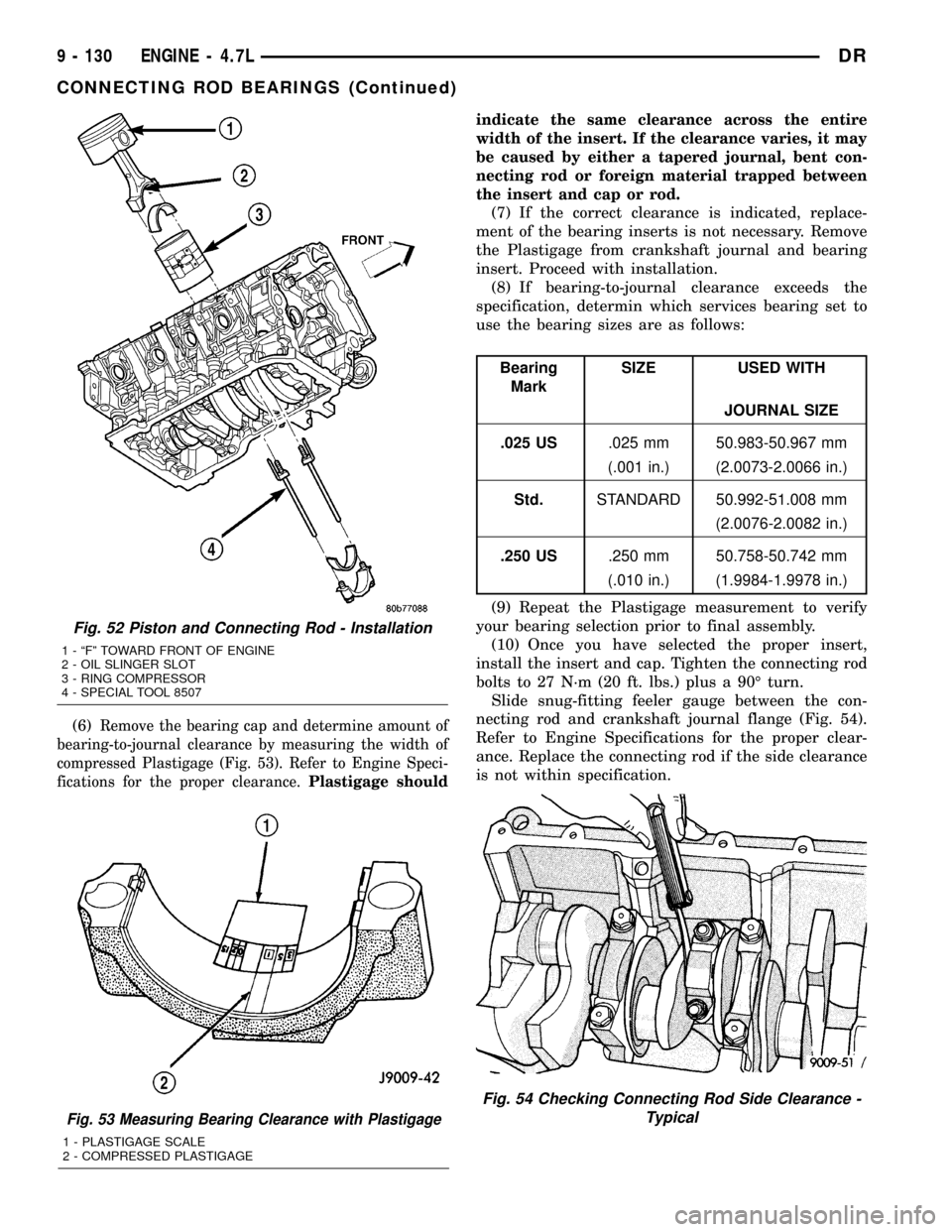
(6)Remove the bearing cap and determine amount of
bearing-to-journal clearance by measuring the width of
compressed Plastigage (Fig. 53). Refer to Engine Speci-
fications for the proper clearance.Plastigage shouldindicate the same clearance across the entire
width of the insert. If the clearance varies, it may
be caused by either a tapered journal, bent con-
necting rod or foreign material trapped between
the insert and cap or rod.
(7) If the correct clearance is indicated, replace-
ment of the bearing inserts is not necessary. Remove
the Plastigage from crankshaft journal and bearing
insert. Proceed with installation.
(8) If bearing-to-journal clearance exceeds the
specification, determin which services bearing set to
use the bearing sizes are as follows:
Bearing
MarkSIZE USED WITH
JOURNAL SIZE
.025 US.025 mm 50.983-50.967 mm
(.001 in.) (2.0073-2.0066 in.)
Std.STANDARD 50.992-51.008 mm
(2.0076-2.0082 in.)
.250 US.250 mm 50.758-50.742 mm
(.010 in.) (1.9984-1.9978 in.)
(9) Repeat the Plastigage measurement to verify
your bearing selection prior to final assembly.
(10) Once you have selected the proper insert,
install the insert and cap. Tighten the connecting rod
bolts to 27 N´m (20 ft. lbs.) plus a 90É turn.
Slide snug-fitting feeler gauge between the con-
necting rod and crankshaft journal flange (Fig. 54).
Refer to Engine Specifications for the proper clear-
ance. Replace the connecting rod if the side clearance
is not within specification.
Fig. 53 Measuring Bearing Clearance with Plastigage
1 - PLASTIGAGE SCALE
2 - COMPRESSED PLASTIGAGE
Fig. 52 Piston and Connecting Rod - Installation
1 - ªFº TOWARD FRONT OF ENGINE
2 - OIL SLINGER SLOT
3 - RING COMPRESSOR
4 - SPECIAL TOOL 8507
Fig. 54 Checking Connecting Rod Side Clearance -
Typical
9 - 130 ENGINE - 4.7LDR
CONNECTING ROD BEARINGS (Continued)