1998 DODGE RAM 1500 center console
[x] Cancel search: center consolePage 1156 of 2627
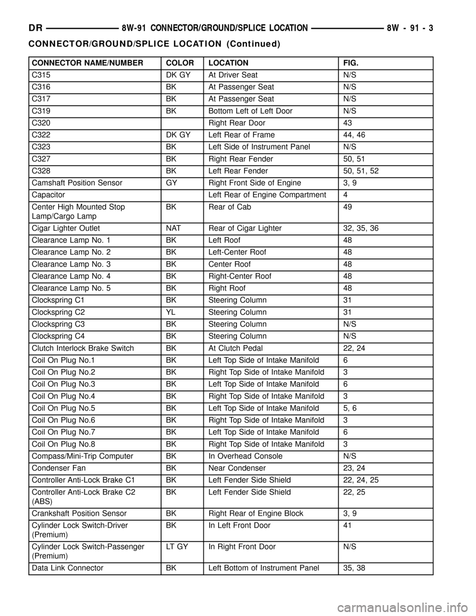
CONNECTOR NAME/NUMBER COLOR LOCATION FIG.
C315 DK GY At Driver Seat N/S
C316 BK At Passenger Seat N/S
C317 BK At Passenger Seat N/S
C319 BK Bottom Left of Left Door N/S
C320 Right Rear Door 43
C322 DK GY Left Rear of Frame 44, 46
C323 BK Left Side of Instrument Panel N/S
C327 BK Right Rear Fender 50, 51
C328 BK Left Rear Fender 50, 51, 52
Camshaft Position Sensor GY Right Front Side of Engine 3, 9
Capacitor Left Rear of Engine Compartment 4
Center High Mounted Stop
Lamp/Cargo LampBK Rear of Cab 49
Cigar Lighter Outlet NAT Rear of Cigar Lighter 32, 35, 36
Clearance Lamp No. 1 BK Left Roof 48
Clearance Lamp No. 2 BK Left-Center Roof 48
Clearance Lamp No. 3 BK Center Roof 48
Clearance Lamp No. 4 BK Right-Center Roof 48
Clearance Lamp No. 5 BK Right Roof 48
Clockspring C1 BK Steering Column 31
Clockspring C2 YL Steering Column 31
Clockspring C3 BK Steering Column N/S
Clockspring C4 BK Steering Column N/S
Clutch Interlock Brake Switch BK At Clutch Pedal 22, 24
Coil On Plug No.1 BK Left Top Side of Intake Manifold 6
Coil On Plug No.2 BK Right Top Side of Intake Manifold 3
Coil On Plug No.3 BK Left Top Side of Intake Manifold 6
Coil On Plug No.4 BK Right Top Side of Intake Manifold 3
Coil On Plug No.5 BK Left Top Side of Intake Manifold 5, 6
Coil On Plug No.6 BK Right Top Side of Intake Manifold 3
Coil On Plug No.7 BK Left Top Side of Intake Manifold 6
Coil On Plug No.8 BK Right Top Side of Intake Manifold 3
Compass/Mini-Trip Computer BK In Overhead Console N/S
Condenser Fan BK Near Condenser 23, 24
Controller Anti-Lock Brake C1 BK Left Fender Side Shield 22, 24, 25
Controller Anti-Lock Brake C2
(ABS)BK Left Fender Side Shield 22, 25
Crankshaft Position Sensor BK Right Rear of Engine Block 3, 9
Cylinder Lock Switch-Driver
(Premium)BK In Left Front Door 41
Cylinder Lock Switch-Passenger
(Premium)LT GY In Right Front Door N/S
Data Link Connector BK Left Bottom of Instrument Panel 35, 38
DR8W-91 CONNECTOR/GROUND/SPLICE LOCATION 8W - 91 - 3
CONNECTOR/GROUND/SPLICE LOCATION (Continued)
Page 1159 of 2627
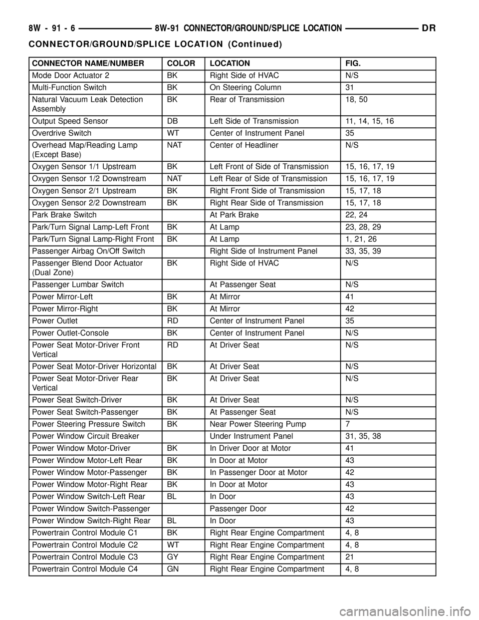
CONNECTOR NAME/NUMBER COLOR LOCATION FIG.
Mode Door Actuator 2 BK Right Side of HVAC N/S
Multi-Function Switch BK On Steering Column 31
Natural Vacuum Leak Detection
AssemblyBK Rear of Transmission 18, 50
Output Speed Sensor DB Left Side of Transmission 11, 14, 15, 16
Overdrive Switch WT Center of Instrument Panel 35
Overhead Map/Reading Lamp
(Except Base)NAT Center of Headliner N/S
Oxygen Sensor 1/1 Upstream BK Left Front of Side of Transmission 15, 16, 17, 19
Oxygen Sensor 1/2 Downstream NAT Left Rear of Side of Transmission 15, 16, 17, 19
Oxygen Sensor 2/1 Upstream BK Right Front Side of Transmission 15, 17, 18
Oxygen Sensor 2/2 Downstream BK Right Rear Side of Transmission 15, 17, 18
Park Brake Switch At Park Brake 22, 24
Park/Turn Signal Lamp-Left Front BK At Lamp 23, 28, 29
Park/Turn Signal Lamp-Right Front BK At Lamp 1, 21, 26
Passenger Airbag On/Off Switch Right Side of Instrument Panel 33, 35, 39
Passenger Blend Door Actuator
(Dual Zone)BK Right Side of HVAC N/S
Passenger Lumbar Switch At Passenger Seat N/S
Power Mirror-Left BK At Mirror 41
Power Mirror-Right BK At Mirror 42
Power Outlet RD Center of Instrument Panel 35
Power Outlet-Console BK Center of Instrument Panel N/S
Power Seat Motor-Driver Front
VerticalRD At Driver Seat N/S
Power Seat Motor-Driver Horizontal BK At Driver Seat N/S
Power Seat Motor-Driver Rear
VerticalBK At Driver Seat N/S
Power Seat Switch-Driver BK At Driver Seat N/S
Power Seat Switch-Passenger BK At Passenger Seat N/S
Power Steering Pressure Switch BK Near Power Steering Pump 7
Power Window Circuit Breaker Under Instrument Panel 31, 35, 38
Power Window Motor-Driver BK In Driver Door at Motor 41
Power Window Motor-Left Rear BK In Door at Motor 43
Power Window Motor-Passenger BK In Passenger Door at Motor 42
Power Window Motor-Right Rear BK In Door at Motor 43
Power Window Switch-Left Rear BL In Door 43
Power Window Switch-Passenger Passenger Door 42
Power Window Switch-Right Rear BL In Door 43
Powertrain Control Module C1 BK Right Rear Engine Compartment 4, 8
Powertrain Control Module C2 WT Right Rear Engine Compartment 4, 8
Powertrain Control Module C3 GY Right Rear Engine Compartment 21
Powertrain Control Module C4 GN Right Rear Engine Compartment 4, 8
8W - 91 - 6 8W-91 CONNECTOR/GROUND/SPLICE LOCATIONDR
CONNECTOR/GROUND/SPLICE LOCATION (Continued)
Page 1222 of 2627
becomes transparent and the fuse that has been
assigned the IOD designation becomes only another
Fused B(+) circuit fuse.
The IOD fuse can be used by the vehicle owner as
a convenient means of reducing battery depletion
when a vehicle is to be stored for periods not to
exceed about thirty days. However, it must be
remembered that disconnecting the IOD fuse will not
eliminate IOD, but only reduce this normal condition.
If a vehicle will be stored for more than about thirty
days, the battery negative cable should be discon-
nected to eliminate normal IOD; and, the battery
should be tested and recharged at regular intervals
during the vehicle storage period to prevent the bat-
tery from becoming discharged or damaged.
REMOVAL
The Ignition-Off Draw (IOD) fuse is disconnected
from Integrated Power Module fuse cavity # 51 when
the vehicle is shipped from the assembly plant.
Dealer personnel must reconnect the IOD fuse when
the vehicle is being prepared for delivery in order to
restore full electrical system operation.
(1) Turn the ignition switch to the Off position.
(2) Remove the Integrated Power Module cover.
(3) Grasp the outer tabs of the IOD fuse holder
unit in fuse cavity # 51 between the thumb and fore-
finger and pull the unit firmly upward.
(4) Install the Integrated Power Module cover.
INSTALLATION
(1) Turn the ignition switch to the Off position.
(2) Remove the Integrated Power Module cover.
(3) To install the IOD fuse, use a thumb to press
the IOD fuse holder unit in fuse cavity # 51 firmly
into the Integrated Power Module.
(4) Install the Integrated Power Module cover.
POWER OUTLET
DESCRIPTION
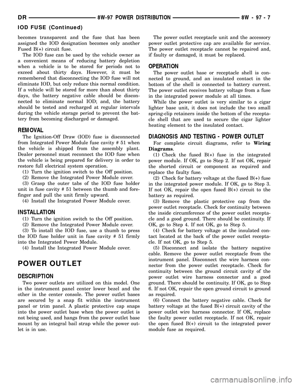
Two power outlets are utilized on this model. One
in the instrument panel center lower bezel and the
other in the center console. The power outlet bases
are secured by a snap fit within the instrument
panel or trim panel. A plastic protective cap snaps
into the power outlet base when the power outlet is
not being used, and hangs from the power outlet base
mount by an integral bail strap while the power out-
let is in use.The power outlet receptacle unit and the accessory
power outlet protective cap are available for service.
The power outlet receptacle cannot be repaired and,
if faulty or damaged, it must be replaced.
OPERATION
The power outlet base or receptacle shell is con-
nected to ground, and an insulated contact in the
bottom of the shell is connected to battery current.
The power outlet receives battery voltage from a fuse
in the integrated power module at all times.
While the power outlet is very similar to a cigar
lighter base unit, it does not include the two small
spring-clip retainers inside the bottom of the recepta-
cle shell that are used to secure the cigar lighter
heating element to the insulated contact.
DIAGNOSIS AND TESTING - POWER OUTLET
For complete circuit diagrams, refer toWiring
Diagrams.
(1) Check the fused B(+) fuse in the integrated
power module. If OK, go to Step 2. If not OK, repair
the shorted circuit or component as required and
replace the faulty fuse.
(2) Check for battery voltage at the fused B(+) fuse
in the integrated power module. If OK, go to Step 3.
If not OK, repair the open fused B(+) circuit to the
battery as required.
(3) Remove the plastic protective cap from the
power outlet receptacle. Check for continuity between
the inside circumference of the power outlet recepta-
cle and a good ground. There should be continuity. If
OK, go to Step 4. If not OK, go to Step 5.
(4) Check for battery voltage at the insulated con-
tact located at the back of the power outlet recepta-
cle. If not OK, go to Step 5.
(5) Disconnect and isolate the battery negative
cable. Remove the power outlet receptacle from the
instrument panel. Disconnect the wire harness con-
nector from the power outlet receptacle. Check for
continuity between the ground circuit cavity of the
power outlet wire harness connector and a good
ground. There should be continuity. If OK, go to Step
6. If not OK, repair the open ground circuit to ground
as required.
(6) Connect the battery negative cable. Check for
battery voltage at the fused B(+) circuit cavity of the
power outlet wire harness connector. If OK, replace
the faulty power outlet receptacle. If not OK, repair
the open fused B(+) circuit to the integrated power
module fuse as required.
DR8W-97 POWER DISTRIBUTION 8W - 97 - 7
IOD FUSE (Continued)
Page 2349 of 2627
(14) Remove the floor console, if equipped. (Refer
to 23 - BODY/INTERIOR/FLOOR CONSOLE -
REMOVAL)
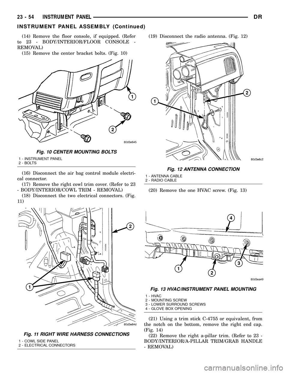
(15) Remove the center bracket bolts. (Fig. 10)
(16) Disconnect the air bag control module electri-
cal connector.
(17) Remove the right cowl trim cover. (Refer to 23
- BODY/INTERIOR/COWL TRIM - REMOVAL)
(18) Disconnect the two electrical connectors. (Fig.
11 )(19) Disconnect the radio antenna. (Fig. 12)
(20) Remove the one HVAC screw. (Fig. 13)
(21) Using a trim stick C-4755 or equivalent, from
the notch on the bottom, remove the right end cap.
(Fig. 14)
(22) Remove the right a-pillar trim. (Refer to 23 -
BODY/INTERIOR/A-PILLAR TRIM/GRAB HANDLE
- REMOVAL)
Fig. 10 CENTER MOUNTING BOLTS
1 - INSTRUMENT PANEL
2 - BOLTS
Fig. 11 RIGHT WIRE HARNESS CONNECTIONS
1 - COWL SIDE PANEL
2 - ELECTRICAL CONNECTORS
Fig. 12 ANTENNA CONNECTION
1 - ANTENNA CABLE
2 - RADIO CABLE
Fig. 13 HVAC/INSTRUMENT PANEL MOUNTING
1-HVAC
2 - MOUNTING SCREW
3 - LOWER SURROUND SCREWS
4 - GLOVE BOX OPENING
23 - 54 INSTRUMENT PANELDR
INSTRUMENT PANEL ASSEMBLY (Continued)
Page 2351 of 2627
(8) Install the left a-pillar trim. (Refer to 23 -
BODY/INTERIOR/A-PILLAR TRIM - INSTALLA-
TION)
(9) Position the left end cap and seat the attach-
ment clips fully.
(10) Install the right side mounting bolts on the
a-pillar and one right mounting bolt on the cowl side
panel and tighten to 12 N´m (9 ft. lbs.).
(11) Install the right a-pillar trim panel. (Refer to
23 - BODY/INTERIOR/A-PILLAR TRIM - INSTAL-
LATION)
(12) Position the right end cap and seat the
attachment clips fully.
(13) Install the one HVAC mounting screw.
(14) Connect the radio antenna.
(15) Connect the two electrical connectors at the
right cowl panel.
(16) Install the right cowl trim cover. (Refer to 23 -
BODY/INTERIOR/COWL TRIM - INSTALLATION)
(17) Connect the air bag control module electrical
connector.
(18) Install the center bracket bolts and tighten to
12 N´m (9 ft. lbs.).
(19) Install the floor console, if equipped. (Refer to
23 - BODY/INTERIOR/FLOOR CONSOLE - INSTAL-
LATION)
(20) Install the air bag control module cover, if
equipped.
(21) Connect the park brake release handle actua-
tor rod.
(22) Install the hood release handle and tighten
the screws.
(23) Install the two bolts at the column support
bracket and tighten to 14 N´m (10 ft. lbs.).
(24) Install the steering column. (Refer to 19 -
STEERING/COLUMN - INSTALLATION)
(25) Connect the wire harness electrical connectors
above the brake pedal.
(26) Install the two top instrument panel bolts and
tighten to 12 N´m (9 ft. lbs.).
(27) Install the four top instrument panel screws.
(28) Install the instrument panel top cover. (Refer
to 23 - BODY/INSTRUMENT PANEL/INSTRUMENT
PANEL TOP COVER - INSTALLATION)
INSTRUMENT PANEL
HEADLAMP SWITCH BEZEL
REMOVAL
WARNING: ON VEHICLES EQUIPPED WITH AIR-
BAGS, DISABLE THE AIRBAG SYSTEM BEFORE
ATTEMPTING ANY STEERING WHEEL, STEERING
COLUMN, SEAT BELT TENSIONER, OR INSTRU-
MENT PANEL COMPONENT DIAGNOSIS OR SER-VICE. DISCONNECT AND ISOLATE THE BATTERY
NEGATIVE (GROUND) CABLE, THEN WAIT TWO
MINUTES FOR THE AIRBAG SYSTEM CAPACITOR
TO DISCHARGE BEFORE PERFORMING FURTHER
DIAGNOSIS OR SERVICE. THIS IS THE ONLY SURE
WAY TO DISABLE THE AIRBAG SYSTEM. FAILURE
TO TAKE THE PROPER PRECAUTIONS COULD
RESULT IN ACCIDENTAL AIRBAG DEPLOYMENT
AND POSSIBLE PERSONAL INJURY.
(1) Using a trim stick C-4755 or equivalent,
release the top clips on the steering column opening
cover and the lower drivers side bezel.
(2) Using a trim stick C-4755 or equivalent,
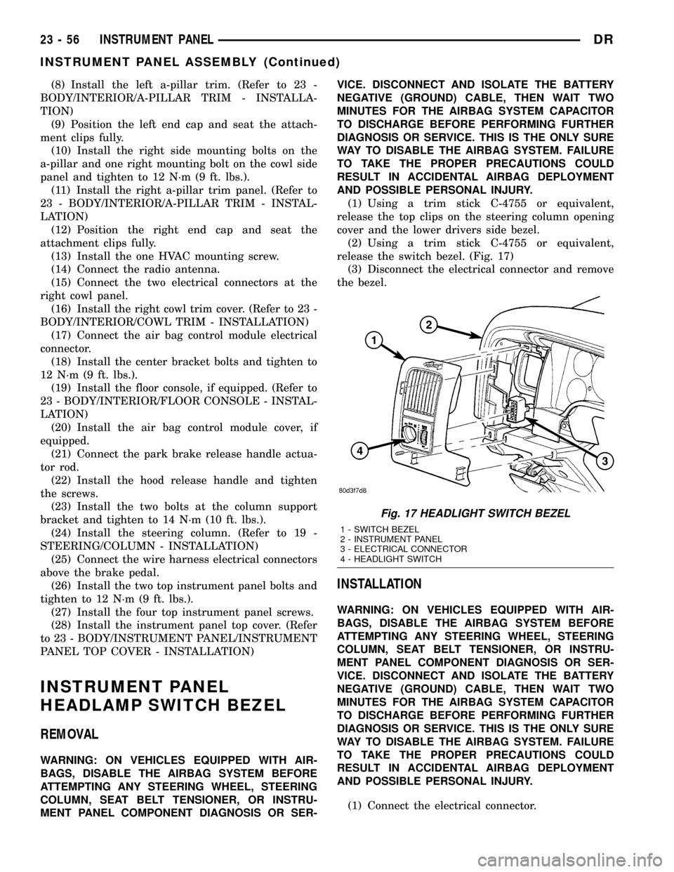
release the switch bezel. (Fig. 17)
(3) Disconnect the electrical connector and remove
the bezel.
INSTALLATION
WARNING: ON VEHICLES EQUIPPED WITH AIR-
BAGS, DISABLE THE AIRBAG SYSTEM BEFORE
ATTEMPTING ANY STEERING WHEEL, STEERING
COLUMN, SEAT BELT TENSIONER, OR INSTRU-
MENT PANEL COMPONENT DIAGNOSIS OR SER-
VICE. DISCONNECT AND ISOLATE THE BATTERY
NEGATIVE (GROUND) CABLE, THEN WAIT TWO
MINUTES FOR THE AIRBAG SYSTEM CAPACITOR
TO DISCHARGE BEFORE PERFORMING FURTHER
DIAGNOSIS OR SERVICE. THIS IS THE ONLY SURE
WAY TO DISABLE THE AIRBAG SYSTEM. FAILURE
TO TAKE THE PROPER PRECAUTIONS COULD
RESULT IN ACCIDENTAL AIRBAG DEPLOYMENT
AND POSSIBLE PERSONAL INJURY.
(1) Connect the electrical connector.
Fig. 17 HEADLIGHT SWITCH BEZEL
1 - SWITCH BEZEL
2 - INSTRUMENT PANEL
3 - ELECTRICAL CONNECTOR
4 - HEADLIGHT SWITCH
23 - 56 INSTRUMENT PANELDR
INSTRUMENT PANEL ASSEMBLY (Continued)
Page 2356 of 2627
(5) Install the steering column opening cover.
(Refer to 23 - BODY/INSTRUMENT PANEL/STEER-
ING COLUMN OPENING COVER - INSTALLA-
TION)
STORAGE BIN
REMOVAL
WARNING: ON VEHICLES EQUIPPED WITH AIR-
BAGS, DISABLE THE AIRBAG SYSTEM BEFORE
ATTEMPTING ANY STEERING WHEEL, STEERING
COLUMN, SEAT BELT TENSIONER, OR INSTRU-
MENT PANEL COMPONENT DIAGNOSIS OR SER-
VICE. DISCONNECT AND ISOLATE THE BATTERY
NEGATIVE (GROUND) CABLE, THEN WAIT TWO
MINUTES FOR THE AIRBAG SYSTEM CAPACITOR
TO DISCHARGE BEFORE PERFORMING FURTHER
DIAGNOSIS OR SERVICE. THIS IS THE ONLY SURE
WAY TO DISABLE THE AIRBAG SYSTEM. FAILURE
TO TAKE THE PROPER PRECAUTIONS COULD
RESULT IN ACCIDENTAL AIRBAG DEPLOYMENT
AND POSSIBLE PERSONAL INJURY.
(1) Remove the center bezel. (Refer to 23 - BODY/
INSTRUMENT PANEL/INSTRUMENT PANEL
CENTER BEZEL - REMOVAL)(2) Remove the floor console. (Refer to 23 - BODY/
INTERIOR/FLOOR CONSOLE - REMOVAL)
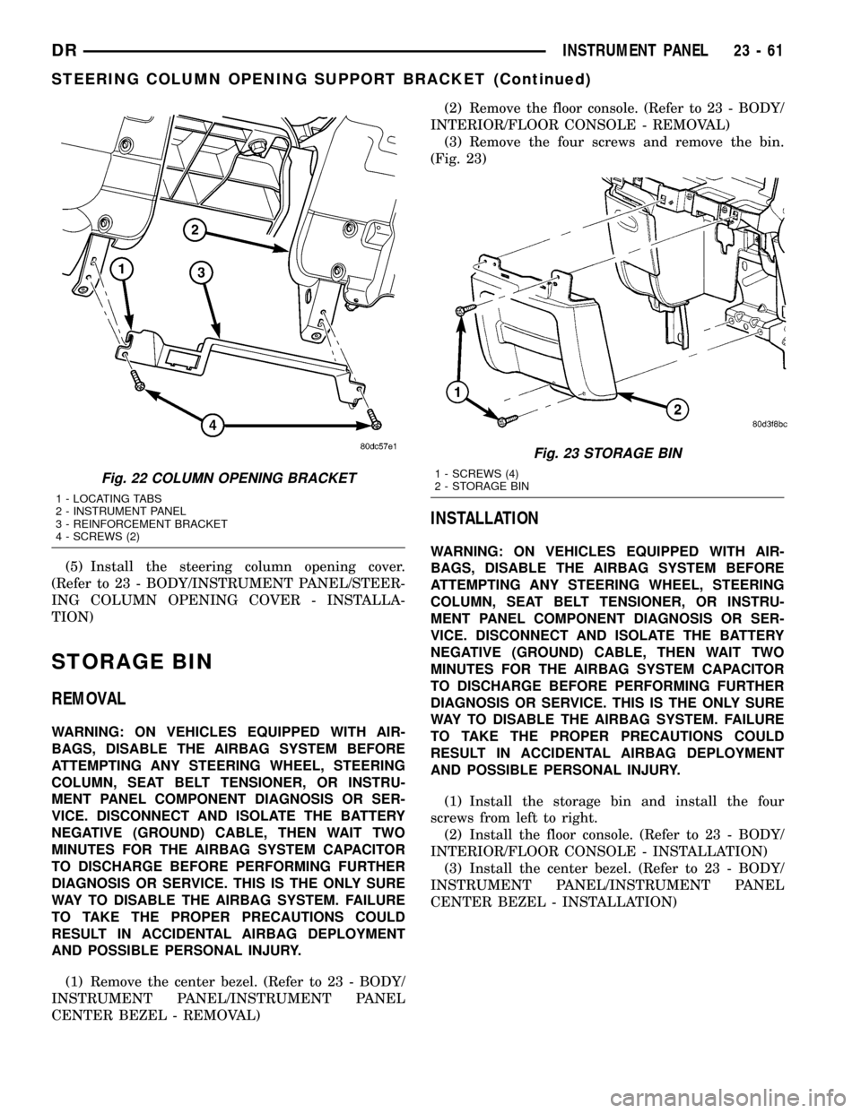
(3) Remove the four screws and remove the bin.
(Fig. 23)
INSTALLATION
WARNING: ON VEHICLES EQUIPPED WITH AIR-
BAGS, DISABLE THE AIRBAG SYSTEM BEFORE
ATTEMPTING ANY STEERING WHEEL, STEERING
COLUMN, SEAT BELT TENSIONER, OR INSTRU-
MENT PANEL COMPONENT DIAGNOSIS OR SER-
VICE. DISCONNECT AND ISOLATE THE BATTERY
NEGATIVE (GROUND) CABLE, THEN WAIT TWO
MINUTES FOR THE AIRBAG SYSTEM CAPACITOR
TO DISCHARGE BEFORE PERFORMING FURTHER
DIAGNOSIS OR SERVICE. THIS IS THE ONLY SURE
WAY TO DISABLE THE AIRBAG SYSTEM. FAILURE
TO TAKE THE PROPER PRECAUTIONS COULD
RESULT IN ACCIDENTAL AIRBAG DEPLOYMENT
AND POSSIBLE PERSONAL INJURY.
(1) Install the storage bin and install the four
screws from left to right.
(2) Install the floor console. (Refer to 23 - BODY/
INTERIOR/FLOOR CONSOLE - INSTALLATION)
(3) Install the center bezel. (Refer to 23 - BODY/
INSTRUMENT PANEL/INSTRUMENT PANEL
CENTER BEZEL - INSTALLATION)
Fig. 22 COLUMN OPENING BRACKET
1 - LOCATING TABS
2 - INSTRUMENT PANEL
3 - REINFORCEMENT BRACKET
4 - SCREWS (2)
Fig. 23 STORAGE BIN
1 - SCREWS (4)
2 - STORAGE BIN
DRINSTRUMENT PANEL 23 - 61
STEERING COLUMN OPENING SUPPORT BRACKET (Continued)
Page 2363 of 2627
HEADLINER
REMOVAL
(1) Remove the a-pillar trim. (Refer to 23 - BODY/
INTERIOR/A-PILLAR TRIM - REMOVAL)
(2) Remove the upper b-pillar trim. (Refer to 23 -
BODY/INTERIOR/B-PILLAR UPPER TRIM -
REMOVAL)
(3) Remove the upper c-pillar trim, if equipped.
(Refer to 23 - BODY/INTERIOR/C-PILLAR TRIM -
REMOVAL)
(4) Remove the coat hooks. (Refer to 23 - BODY/
INTERIOR/COAT HOOK - REMOVAL)
(5) Disconnect the headliner harness electrical con-
nector at the left a-pillar.
(6) Remove the dome lamp. (Refer to 8 - ELEC-
TRICAL/LAMPS/LIGHTING - INTERIOR/DOME
LAMP - REMOVAL)
(7) Remove the overhead console. (Refer to 8 -
ELECTRICAL/OVERHEAD CONSOLE - REMOVAL)
(8) Remove the sun visors. (Refer to 23 - BODY/
INTERIOR/SUN VISOR - REMOVAL)
(9) Remove the sun visor supports. (Refer to 23 -
BODY/INTERIOR/SUN VISOR SUPPORT -
REMOVAL)
(10) Lower the headliner and disconnect the center
high mounted stop light.
(11) Lower the front of the headliner down to the
floor just in front of the instrument panel and
remove through the passenger door.
INSTALLATION
(1) Install the headliner into the vehicle through
the passenger door.
(2) Raise the headliner and insert the right side
above right side pillar trim pieces.
(3) Connect the center high mounted stop light
electrical connector.
(4) Install the sun visor supports. (Refer to 23 -
BODY/INTERIOR/SUN VISOR SUPPORT - INSTAL-
LATION)
(5) Install the coat hooks. (Refer to 23 - BODY/IN-
TERIOR/COAT HOOK - INSTALLATION)
(6) Install the sun visors. (Refer to 23 - BODY/IN-
TERIOR/SUN VISOR - INSTALLATION)
(7) Install the overhead console. (Refer to 8 -
ELECTRICAL/OVERHEAD CONSOLE - INSTALLA-
TION)
(8) Install the dome lamp. (Refer to 8 - ELECTRI-
CAL/LAMPS/LIGHTING - INTERIOR/DOME LAMP
- INSTALLATION)
(9) Connect the headliner harness electrical con-
nector at the left a-pillar.
(10) Install the upper c-pillar trim, if equipped.
(Refer to 23 - BODY/INTERIOR/C-PILLAR TRIM -
INSTALLATION)(11) Install the upper b-pillar trim. (Refer to 23 -
BODY/INTERIOR/B-PILLAR UPPER TRIM -
INSTALLATION)
(12) Install the upper a-pillar trim. (Refer to 23 -
BODY/INTERIOR/A-PILLAR TRIM - INSTALLA-
TION)
B-PILLAR GRAB HANDLE
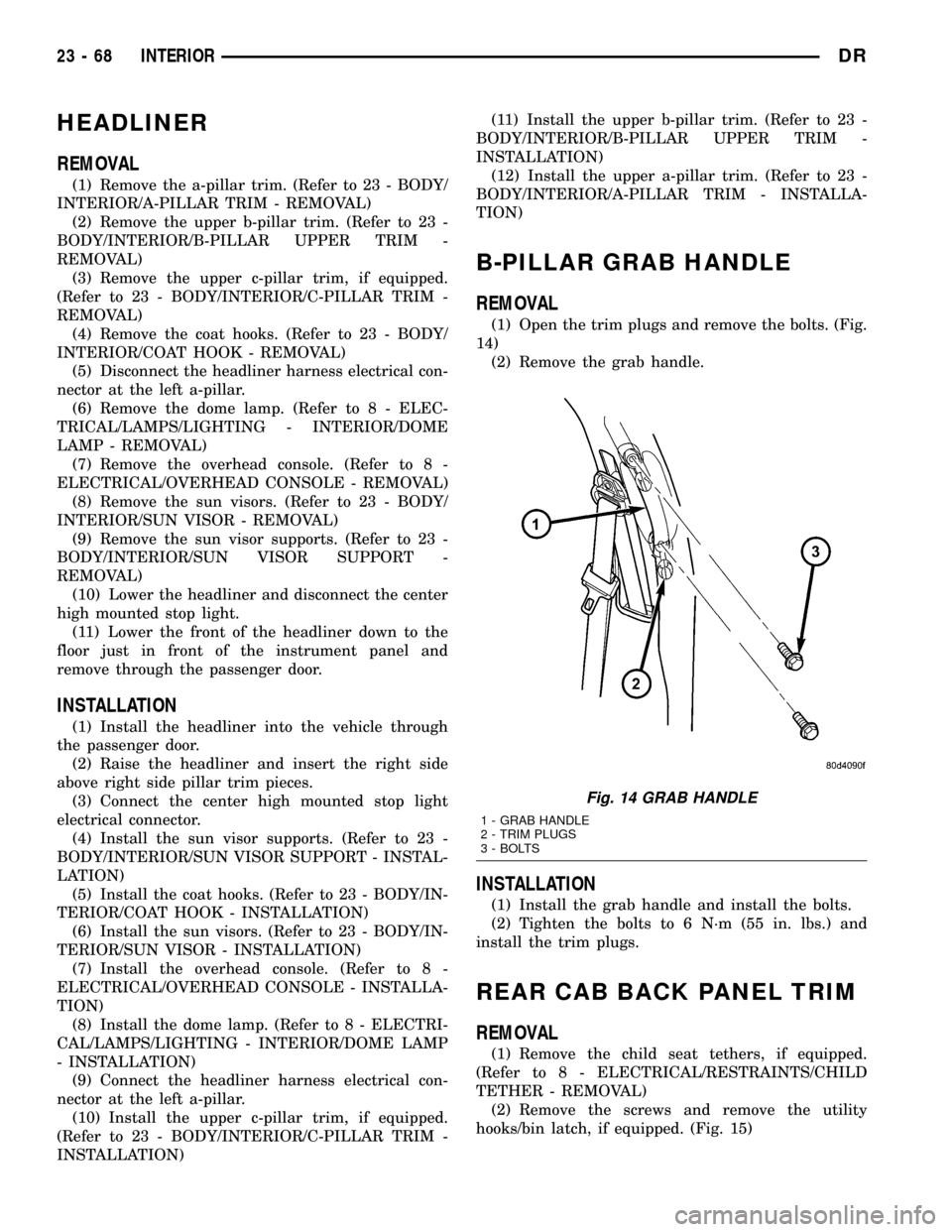
REMOVAL
(1) Open the trim plugs and remove the bolts. (Fig.
14)
(2) Remove the grab handle.
INSTALLATION
(1) Install the grab handle and install the bolts.
(2) Tighten the bolts to 6 N´m (55 in. lbs.) and
install the trim plugs.
REAR CAB BACK PANEL TRIM
REMOVAL
(1) Remove the child seat tethers, if equipped.
(Refer to 8 - ELECTRICAL/RESTRAINTS/CHILD
TETHER - REMOVAL)
(2) Remove the screws and remove the utility
hooks/bin latch, if equipped. (Fig. 15)
Fig. 14 GRAB HANDLE
1 - GRAB HANDLE
2 - TRIM PLUGS
3 - BOLTS
23 - 68 INTERIORDR
Page 2600 of 2627
FIRING ORDER / CABLE ROUTING, 5.7L
V-8 ENGINE..........................8I-4
FIRING ORDER, 3.7L V-6 - ENGINE........8I-4
FIRING ORDER, 4.7L V-8 - ENGINE........8I-4
FIRING ORDER, DIESEL - FUEL
INJECTOR..........................14-48
FITTING - DESCRIPTION, QUICK
CONNECT............................14-8
FITTING - STANDARD PROCEDURE,
CONNECTING ROD BEARING...........9-129
FITTING - STANDARD PROCEDURE,
CRANKSHAFT MAIN BEARING.....9-134,9-207
FITTING - STANDARD PROCEDURE,
PISTON...................9-139,9-211,9-51
FITTING - STANDARD PROCEDURE,
PISTON RING.........9-142,9-213,9-284,9-53
FITTING, STANDARD PROCEDURE -
CONNECTING ROD BEARING............9-49
FITTING, STANDARD PROCEDURE -
MAIN BEARING.......................9-44
FITTINGS - STANDARD PROCEDURE,
HANDLING TUBING...................24-45
FITTINGS - STANDARD PROCEDURE,
QUICK-CONNECT......................14-8
FLAG - INSTALLATION, SIDE VIEW
MIRROR...........................23-27
FLAG - REMOVAL, SIDE VIEW MIRROR . . . 23-27
FLARING - STANDARD PROCEDURE,
DOUBLE INVERTED....................5-10
FLARING - STANDARD PROCEDURE, ISO . . . 5-11
FLEX PLATE - INSTALLATION . . 9-138,9-210,9-48
FLEX PLATE - REMOVAL.......9-138,9-210,9-48
FLOOR - INSTALLATION, LOAD..........23-72
FLOOR - REMOVAL, LOAD.............23-71
FLOOR CONSOLE - INSTALLATION.......23-67
FLOOR CONSOLE - REMOVAL...........23-67
FLOOR DISTRIBUTION DUCT -
INSTALLATION.......................24-34
FLOOR DISTRIBUTION DUCT - REMOVAL . 24-33
FLOOR MATS - INSTALLATION, CARPETS . 23-65
FLOOR MATS - REMOVAL, CARPETS.....23-65
FLOOR SHIFT BOOT - INSTALLATION,
4WD ..............................23-62
FLOOR SHIFT BOOT - REMOVAL, 4WD....23-62
FLOOR SUPPORT CYLINDER -
INSTALLATION, LOAD.................23-72
FLOOR SUPPORT CYLINDER -
REMOVAL, LOAD.....................23-72
FLOW - 5.9L DIESEL - DESCRIPTION,
COOLING SYSTEM.....................7-3
FLOW - DIAGNOSIS AND TESTING,
RADIATOR COOLANT..............7-54,7-56
FLOW 3.7L/4.7L/5.7L ENGINE -
DESCRIPTION, COOLING SYSTEM.........7-1
FLOW AND PRESSURE - DIAGNOSIS
AND TESTING, POWER STEERING........19-4
FLUID - DESCRIPTION................19-43
FLUID - DESCRIPTION, AUTOMATIC
TRANSMISSION.......................0-4
FLUID - DESCRIPTION, POWER
STEERING............................0-3
FLUID - DIAGNOSIS AND TESTING,
CAUSES OF BURNT............21-201,21-366
FLUID - OPERATION, AUTOMATIC
TRANSMISSION.......................0-5
FLUID AND FILTER REPLACEMENT -
STANDARD PROCEDURE........21-203,21-367
FLUID CAPACITIES, SPECIFICATIONS.......0-5
FLUID CONTAMINATION - DIAGNOSIS
AND TESTING................21-202,21-366
FLUID CONTAMINATION - DIAGNOSIS
AND TESTING, BRAKE..................5-23
FLUID COOLER - INSTALLATION.........19-43
FLUID COOLER - REMOVAL............19-43
FLUID DRAIN AND REFILL - STANDARD
PROCEDURE.....21-441,21-476,21-507,21-537,
21-571
FLUID INDICATOR - DESCRIPTION,
WASHER
...........................8J-44
FLUID INDICATOR - OPERATION,
WASHER
...........................8J-44
FLUID LEAK - DIAGNOSIS AND TESTING,
CONVERTER HOUSING
.........21-144,21-318
FLUID LEVEL - DIAGNOSIS AND
TESTING, EFFECTS OF INCORRECT
.....21-201,
21-366
FLUID LEVEL - STANDARD PROCEDURE,
BRAKE
..............................5-23FLUID LEVEL CHECK - STANDARD
PROCEDURE.................21-202,21-366
FLUID LEVEL CHECKING - STANDARD
PROCEDURE, POWER STEERING........19-43
FLUID LEVEL SWITCH - DESCRIPTION,
WASHER............................8R-9
FLUID LEVEL SWITCH - INSTALLATION,
WASHER...........................8R-11
FLUID LEVEL SWITCH - OPERATION,
WASHER............................8R-9
FLUID LEVEL SWITCH - REMOVAL,
WASHER...........................8R-10
FLUID RESERVOIR - INSTALLATION.......5-24
FLUID RESERVOIR - REMOVAL..........5-23
FLUID, SPECIFICATIONS - BRAKE.........5-23
FLUSH - SPECIFICATIONS, GAP.........23-95
FLUSHING - STANDARD PROCEDURE,
COOLING SYSTEM CLEANING/
REVERSE............................7-17
FLUSHING POWER STEERING SYSTEM -
STANDARD PROCEDURE...............19-40
FLYWHEEL - ASSEMBLY................6-11
FLYWHEEL - DIAGNOSIS AND TESTING....6-10
FLYWHEEL - DISASSEMBLY.............6-11
FLYWHEEL - INSTALLATION.............6-11
FLYWHEEL - REMOVAL.................6-11
FOG LAMP - INSTALLATION............8L-12
FOG LAMP - REMOVAL................8L-12
FOG LAMP RELAY - DESCRIPTION.......8L-12
FOG LAMP RELAY - INSTALLATION........8L-13
FOG LAMP RELAY - OPERATION.........8L-13
FOG LAMP RELAY - REMOVAL..........8L-13
FOOTMANS LOOP BRACKETS -
INSTALLATION, SEAT BACK REAR.......23-85
FOOTMANS LOOP BRACKETS -
REMOVAL, SEAT BACK REAR...........23-85
FORM-IN-PLACE GASKETS AND
SEALERS - STANDARD PROCEDURE . . 9-239,9-9,
9-94
FRAME - INSTALLATION, GRILLE........23-40
FRAME - REAR - INSTALLATION, SEAT
CUSHION...........................23-85
FRAME - REAR - REMOVAL, SEAT
CUSHION...........................23-85
FRAME - REMOVAL, GRILLE............23-40
FRAME DIMENSIONS - SPECIFICATIONS . . 13-16
FRAME H-SECTION REPLACEMENT -
STANDARD PROCEDURE, REAR.........13-13
FRAME RAIL TIP REPLACEMENT -
STANDARD PROCEDURE, LIGHT DUTY
FRONT..............................13-4
FREE MODULE - INSTALLATION, HANDS . . . 8T-2
FREE MODULE - REMOVAL, HANDS.......8T-2
FRONT - INSTALLATION....5-16,5-21,5-22,5-34
FRONT - INSTALLATION...............22-14
FRONT - INSTALLATION, CRANKSHAFT
OIL SEAL.............9-136,9-208,9-275,9-46
FRONT - INSTALLATION, PROPELLER
SHAFT - HD...........................3-7
FRONT - INSTALLATION, PROPELLER
SHAFT- LD............................3-7
FRONT - INSTALLATION, SEAT..........23-81
FRONT - INSTALLATION, SEAT BACK
CUSHION / COVER...................23-82
FRONT - INSTALLATION, SEAT CUSHION
/ COVER............................23-83
FRONT - REMOVAL........5-13,5-17,5-21,5-33
FRONT - REMOVAL, CRANKSHAFT OIL
SEAL................9-135,9-208,9-275,9-46
FRONT - REMOVAL, PROPELLER SHAFT
- HD ................................3-7
FRONT - REMOVAL, PROPELLER SHAFT-
LD ..................................3-6
FRONT - REMOVAL, SEAT..............23-81
FRONT - REMOVAL, SEAT BACK
CUSHION / COVER...................23-82
FRONT - REMOVAL, SEAT CUSHION /
COVER.............................23-83
FRONT AIR DAM - INSTALLATION........13-2
FRONT AIR DAM - REMOVAL............13-2
FRONT AXLE - 9 1/4 AA -
ADJUSTMENTS
.......................3-59
FRONT AXLE - 9 1/4 AA - DIAGNOSIS
AND TESTING
........................3-54
FRONT AXLE - 9 1/4 AA - INSTALLATION
. . . 3-58
FRONT AXLE - 9 1/4 AA - REMOVAL
......3-57
FRONT AXLE - 9 1/4 AA - SPECIAL
TOOLS
..............................3-64FRONT AXLE - 9 1/4 AA -
SPECIFICATIONS......................3-63
FRONT AXLE - C205F - ADJUSTMENTS....3-32
FRONT AXLE - C205F - DIAGNOSIS AND
TESTING............................3-27
FRONT AXLE - C205F - INSTALLATION.....3-31
FRONT AXLE - C205F - REMOVAL........3-31
FRONT AXLE - C205F - SPECIAL TOOLS . . . 3-40
FRONT AXLE - C205F - SPECIFICATIONS . . . 3-39
FRONT BEARING - INSTALLATION,
OUTPUT SHAFT.....................21-216
FRONT BEARING - REMOVAL, OUTPUT
SHAFT............................21-216
FRONT BRAKE HOSE - INSTALLATION.....5-13
FRONT BUMPER - INSTALLATION.........13-2
FRONT BUMPER - REMOVAL............13-2
FRONT CENTER SEAT BELT -
INSTALLATION......................8O-31
FRONT CENTER SEAT BELT - REMOVAL . . 8O-30
FRONT CENTER SEAT BELT &
RETRACTOR - INSTALLATION...........8O-29
FRONT CENTER SEAT BELT &
RETRACTOR - REMOVAL..............8O-29
FRONT CLUTCH - ASSEMBLY..........21-207
FRONT CLUTCH - DESCRIPTION........21-205
FRONT CLUTCH - DISASSEMBLY.......21-205
FRONT CLUTCH - INSPECTION.........21-206
FRONT CLUTCH - OPERATION.........21-205
FRONT CONTROL MODULE -
DESCRIPTION.....................8W-97-5
FRONT CONTROL MODULE -
DESCRIPTION........................8E-5
FRONT CONTROL MODULE - DIAGNOSIS
AND TESTING.....................8W-97-5
FRONT CONTROL MODULE - DIAGNOSIS
AND TESTING........................8E-5
FRONT CONTROL MODULE -
INSTALLATION....................8W-97-6
FRONT CONTROL MODULE -
INSTALLATION........................8E-5
FRONT CONTROL MODULE - OPERATION . 8W-97-5
FRONT CONTROL MODULE - OPERATION . . 8E-5
FRONT CONTROL MODULE - REMOVAL . 8W-97-6
FRONT CONTROL MODULE - REMOVAL....8E-5
FRONT CROSSMEMBER - INSTALLATION . . 13-22
FRONT CROSSMEMBER - REMOVAL.....13-22
FRONT DOOR GLASS RUN
WEATHERSTRIP - INSTALLATION........23-92
FRONT DOOR GLASS RUN
WEATHERSTRIP - REMOVAL............23-92
FRONT DOOR INNER BELT MOLDING -
INSTALLATION.......................23-93
FRONT DOOR INNER BELT MOLDING -
REMOVAL..........................23-93
FRONT DOOR OUTER BELT MOLDING -
INSTALLATION.......................23-93
FRONT DOOR OUTER BELT MOLDING -
REMOVAL..........................23-92
FRONT FASCIA - INSTALLATION..........13-3
FRONT FASCIA - REMOVAL..............13-2
FRONT FENDER - INSTALLATION........23-39
FRONT FENDER - REMOVAL............23-39
FRONT FRAME RAIL TIP REPLACEMENT
- STANDARD PROCEDURE, LIGHT
DUTY...............................13-4
FRONT HOSE - REMOVAL...............5-12
FRONT MOUNT - INSTALLATION . . . 9-147,9-218,
9-287,9-59
FRONT MOUNT - REMOVAL . . 9-146,9-217,9-286,
9-58
FRONT OUTBOARD SEAT BELT BUCKLE -
INSTALLATION......................8O-38
FRONT OUTBOARD SEAT BELT BUCKLE -
REMOVAL..........................8O-37
FRONT OUTPUT SHAFT SEAL -
INSTALLATION . . . 21-442,21-477,21-508,21-538,
21-572
FRONT OUTPUT SHAFT SEAL -
REMOVAL . 21-441,21-477,21-507,21-537,21-572
FRONT PARKING BRAKE CABLE -
INSTALLATION........................5-38
FRONT PARKING BRAKE CABLE -
REMOVAL
...........................5-36
FRONT SEAL - INSTALLATION, OIL
PUMP
............................21-391
FRONT SEAL - REMOVAL, OIL PUMP
....21-391
FRONT SERVO - ASSEMBLY
...........21-209
FRONT SERVO - CLEANING
...........21-209
DRINDEX 13
Description Group-Page Description Group-Page Description Group-Page