Page 1672 of 2627

GEAR - INDEPENDENT FRONT SUSPENSION
TABLE OF CONTENTS
page page
GEAR - INDEPENDENT FRONT SUSPENSION
DESCRIPTION.........................17
REMOVAL.............................17
INSTALLATION.........................18
SPECIFICATIONS
TORQUE CHART......................19BUSHING
REMOVAL.............................19
INSTALLATION.........................19
GEAR - INDEPENDENT FRONT
SUSPENSION
DESCRIPTION
A rack and pinion steering gears (Fig. 1) is made
up of two main components, the pinon shaft and the
rack. The gear cannot be adjusted or internally ser-
viced. If a malfunction or a fluid leak occurs, the gear
must be replaced as an assembly.
REMOVAL
NOTE: The steering column on vehicles with an
automatic transmission may not be equipped with
an internal locking shaft that allows the ignition key
cylinder to be locked with the key. Alternative meth-
ods of locking the steering wheel for service will
have to be used.
(1) Lock the steering wheel.(2) Drain and siphon the power steering fluid from
the reservoir.
(3) Raise the vehicle.
(4) Remove and discard the steering coupler pinch
bolt.
(5) Remove the power steering hoses from the rack
& pinion.
(6) Remove the tire and wheel assembly.
(7) Remove the tie rod end nuts and separate tie
rod ends from the knuckles with Special tool 8677
(Refer to 19 - STEERING/LINKAGE/TIE ROD END -
REMOVAL).
(8) Remove the skid plate (Refer to 13 - FRAME &
BUMPERS/FRAME/FRONT SKID PLATE -
REMOVAL).
(9) Remove the rack & pinion mounting bolts. (Fig.
2) & (Fig. 3)
(10) Remove the rack & pinion from the vehicle.
Fig. 1 STEERING GEAR
1 - OUTER TIE ROD ENDS
2 - MOUNTING BUSHINGS
3 - BELLOWS
Fig. 2 STEERING GEAR MOUNTING BOLTS
1 - STEERING GEAR MOUNTING BOLTS 4X4
DRGEAR - INDEPENDENT FRONT SUSPENSION 19 - 17
Page 2162 of 2627

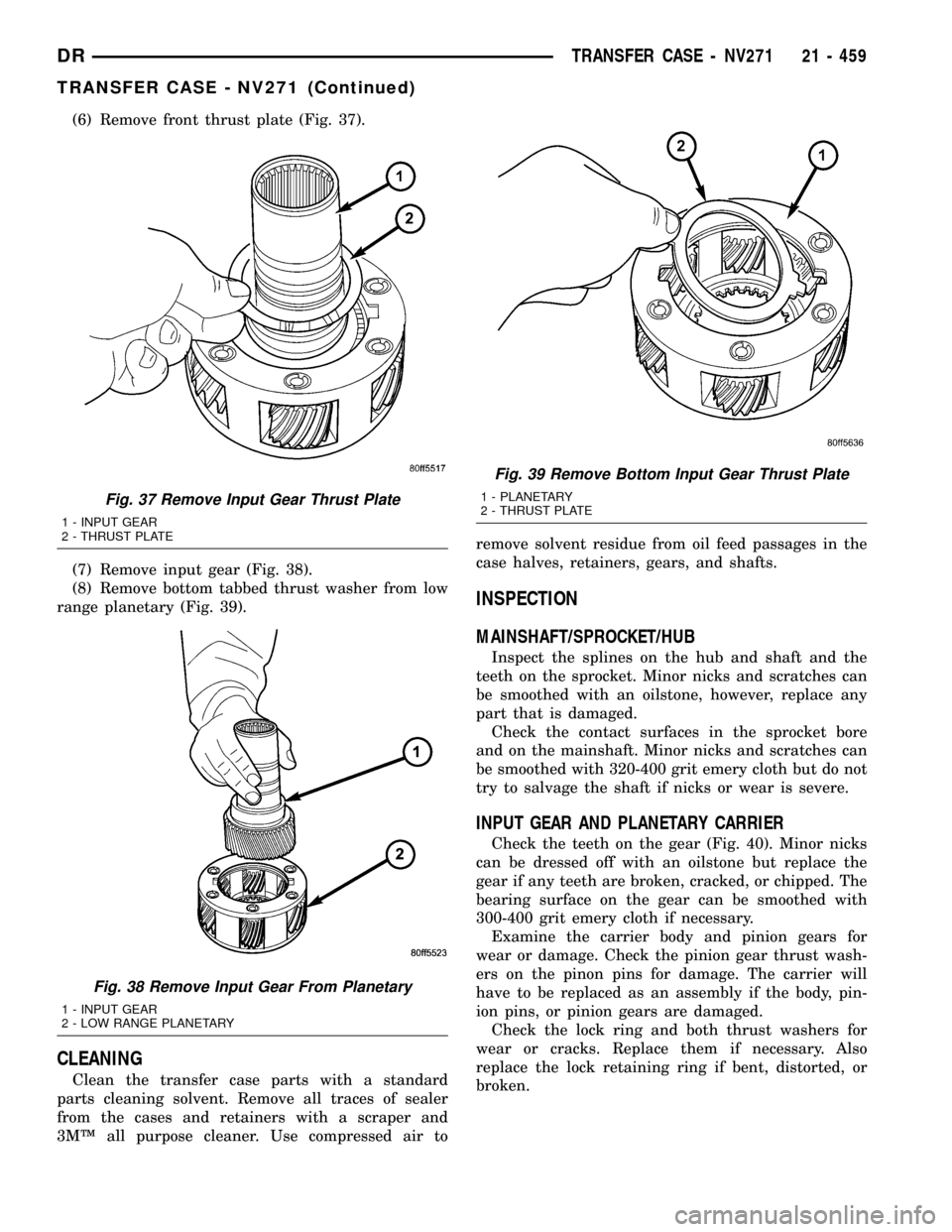
(6) Remove front thrust plate (Fig. 37).
(7) Remove input gear (Fig. 38).
(8) Remove bottom tabbed thrust washer from low
range planetary (Fig. 39).
CLEANING
Clean the transfer case parts with a standard
parts cleaning solvent. Remove all traces of sealer
from the cases and retainers with a scraper and
3MŸ all purpose cleaner. Use compressed air toremove solvent residue from oil feed passages in the
case halves, retainers, gears, and shafts.
INSPECTION
MAINSHAFT/SPROCKET/HUB
Inspect the splines on the hub and shaft and the
teeth on the sprocket. Minor nicks and scratches can
be smoothed with an oilstone, however, replace any
part that is damaged.
Check the contact surfaces in the sprocket bore
and on the mainshaft. Minor nicks and scratches can
be smoothed with 320-400 grit emery cloth but do not
try to salvage the shaft if nicks or wear is severe.
INPUT GEAR AND PLANETARY CARRIER
Check the teeth on the gear (Fig. 40). Minor nicks
can be dressed off with an oilstone but replace the
gear if any teeth are broken, cracked, or chipped. The
bearing surface on the gear can be smoothed with
300-400 grit emery cloth if necessary.
Examine the carrier body and pinion gears for
wear or damage. Check the pinion gear thrust wash-
ers on the pinon pins for damage. The carrier will
have to be replaced as an assembly if the body, pin-
ion pins, or pinion gears are damaged.
Check the lock ring and both thrust washers for
wear or cracks. Replace them if necessary. Also
replace the lock retaining ring if bent, distorted, or
broken.
Fig. 37 Remove Input Gear Thrust Plate
1 - INPUT GEAR
2 - THRUST PLATE
Fig. 38 Remove Input Gear From Planetary
1 - INPUT GEAR
2 - LOW RANGE PLANETARY
Fig. 39 Remove Bottom Input Gear Thrust Plate
1 - PLANETARY
2 - THRUST PLATE
DRTRANSFER CASE - NV271 21 - 459
TRANSFER CASE - NV271 (Continued)
Page 2257 of 2627

(8) Remove bottom tabbed thrust washer from low
range planetary (Fig. 38).
CLEANING
Clean the transfer case parts with a standard
parts cleaning solvent. Remove all traces of sealer
from the cases and retainers with a scraper and
3MŸ all purpose cleaner. Use compressed air to
remove solvent residue from oil feed passages in the
case halves, retainers, gears, and shafts.
INSPECTION
MAINSHAFT/SPROCKET/HUB INSPECTION
Inspect the splines on the hub and shaft and the
teeth on the sprocket. Minor nicks and scratches can
be smoothed with an oilstone. However, replace any
part that is damaged.
Check the contact surfaces in the sprocket bore
and on the mainshaft. Minor nicks and scratches can
be smoothed with 320-400 grit emery cloth but do not
try to salvage the shaft if nicks or wear is severe.
INPUT GEAR AND PLANETARY CARRIER
Check the teeth on the gear (Fig. 39). Minor nicks
can be dressed off with an oilstone but replace the
gear if any teeth are broken, cracked, or chipped. The
bearing surface on the gear can be smoothed with
300-400 grit emery cloth if necessary.
Examine the carrier body and pinion gears for
wear or damage. Check the pinion gear thrust wash-
ers on the pinon pins for damage. The carrier will
have to be replaced as an assembly if the body, pin-
ion pins, or pinion gears are damaged.
Check the lock ring and both thrust washers for
wear or cracks. Replace them if necessary. Also
replace the lock retaining ring if bent, distorted, or
broken.
Fig. 39 Input Gear And Carrier Components
1 - PLANETARY CARRIER 4 - CARRIER LOCK RING
2 - REAR THRUST WASHER 5 - CARRIER LOCK RETAINING RING
3 - FRONT THRUST WASHER 6 - INPUT GEAR
Fig. 38 Remove Bottom Input Gear Thrust Plate
1 - PLANETARY
2 - THRUST PLATE
21 - 554 TRANSFER CASE - NV273DR
TRANSFER CASE - NV273 (Continued)