1998 DODGE RAM 1500 ad blue
[x] Cancel search: ad bluePage 1118 of 2627
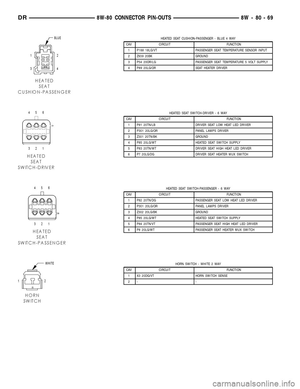
HEATED SEAT CUSHION-PASSENGER - BLUE 4 WAY
CAV CIRCUIT FUNCTION
1 P188 18LG/VT PASSENGER SEAT TEMPERATURE SENSOR INPUT
2 Z939 20BK GROUND
3 P54 20OR/LG PASSENGER SEAT TEMPERATURE 5 VOLT SUPPLY
4 P89 20LG/OR SEAT HEATER DRIVER
HEATED SEAT SWITCH-DRIVER-6WAY
CAV CIRCUIT FUNCTION
1 P81 20TN/LB DRIVER SEAT LOW HEAT LED DRIVER
2 P301 20LG/OR PANEL LAMPS DRIVER
3 Z301 20TN/BK GROUND
4 P85 20LG/WT HEATED SEAT SWITCH SUPPLY
5 P83 20TN/WT DRIVER SEAT HIGH HEAT LED DRIVER
6 P7 20LG/DG DRIVER SEAT HEATER MUX SWITCH
HEATED SEAT SWITCH-PASSENGER-6WAY
CAV CIRCUIT FUNCTION
1 P82 20TN/DG PASSENGER SEAT LOW HEAT LED DRIVER
2 P301 20LG/OR PANEL LAMPS DRIVER
3 Z302 20LG/BK GROUND
4 P85 20LG/WT HEATED SEAT SWITCH SUPPLY
5 P84 20TN/VT PASSENGER SEAT HIGH HEAT LED DRIVER
6 P8 20LG/WT PASSENGER SEAT HEATER MUX SWITCH
HORN SWITCH - WHITE 2 WAY
CAV CIRCUIT FUNCTION
1 X3 20DG/VT HORN SWITCH SENSE
2- -
DR8W-80 CONNECTOR PIN-OUTS 8W - 80 - 69
Page 1129 of 2627
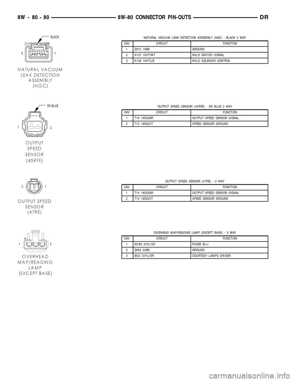
NATURAL VACUUM LEAK DETECTION ASSEMBLY (NGC) - BLACK 3 WAY
CAV CIRCUIT FUNCTION
1 Z910 18BK GROUND
2 K107 18VT/WT NVLD SWITCH SIGNAL
3 K106 18VT/LB NVLD SOLENOID CONTROL
OUTPUT SPEED SENSOR (45RFE) - DK BLUE 2 WAY
CAV CIRCUIT FUNCTION
1 T14 18DG/BR OUTPUT SPEED SENSOR SIGNAL
2 T13 18DG/VT SPEED SENSOR GROUND
OUTPUT SPEED SENSOR (47RE)-2WAY
CAV CIRCUIT FUNCTION
1 T14 18DG/BR OUTPUT SPEED SENSOR SIGNAL
2 T13 18DG/VT SPEED SENSOR GROUND
OVERHEAD MAP/READING LAMP (EXCEPT BASE)-3WAY
CAV CIRCUIT FUNCTION
1 M288 20YL/GY FUSED B(+)
2 Z964 20BK GROUND
3 M22 20YL/OR COURTESY LAMPS DRIVER
8W - 80 - 80 8W-80 CONNECTOR PIN-OUTSDR
Page 1136 of 2627
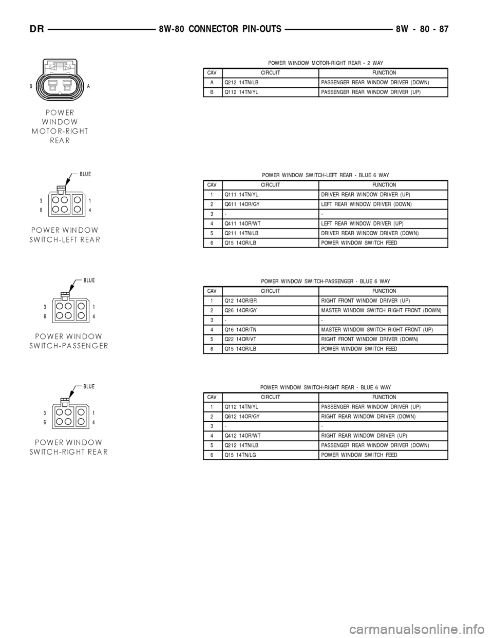
POWER WINDOW MOTOR-RIGHT REAR-2WAY
CAV CIRCUIT FUNCTION
A Q212 14TN/LB PASSENGER REAR WINDOW DRIVER (DOWN)
B Q112 14TN/YL PASSENGER REAR WINDOW DRIVER (UP)
POWER WINDOW SWITCH-LEFT REAR - BLUE 6 WAY
CAV CIRCUIT FUNCTION
1 Q111 14TN/YL DRIVER REAR WINDOW DRIVER (UP)
2 Q611 14OR/GY LEFT REAR WINDOW DRIVER (DOWN)
3- -
4 Q411 14OR/WT LEFT REAR WINDOW DRIVER (UP)
5 Q211 14TN/LB DRIVER REAR WINDOW DRIVER (DOWN)
6 Q15 14OR/LB POWER WINDOW SWITCH FEED
POWER WINDOW SWITCH-PASSENGER - BLUE 6 WAY
CAV CIRCUIT FUNCTION
1 Q12 14OR/BR RIGHT FRONT WINDOW DRIVER (UP)
2 Q26 14OR/GY MASTER WINDOW SWITCH RIGHT FRONT (DOWN)
3- -
4 Q16 14OR/TN MASTER WINDOW SWITCH RIGHT FRONT (UP)
5 Q22 14OR/VT RIGHT FRONT WINDOW DRIVER (DOWN)
6 Q15 14OR/LB POWER WINDOW SWITCH FEED
POWER WINDOW SWITCH-RIGHT REAR - BLUE 6 WAY
CAV CIRCUIT FUNCTION
1 Q112 14TN/YL PASSENGER REAR WINDOW DRIVER (UP)
2 Q612 14OR/GY RIGHT REAR WINDOW DRIVER (DOWN)
3- -
4 Q412 14OR/WT RIGHT REAR WINDOW DRIVER (UP)
5 Q212 14TN/LB PASSENGER REAR WINDOW DRIVER (DOWN)
6 Q15 14TN/LG POWER WINDOW SWITCH FEED
DR8W-80 CONNECTOR PIN-OUTS 8W - 80 - 87
Page 1219 of 2627
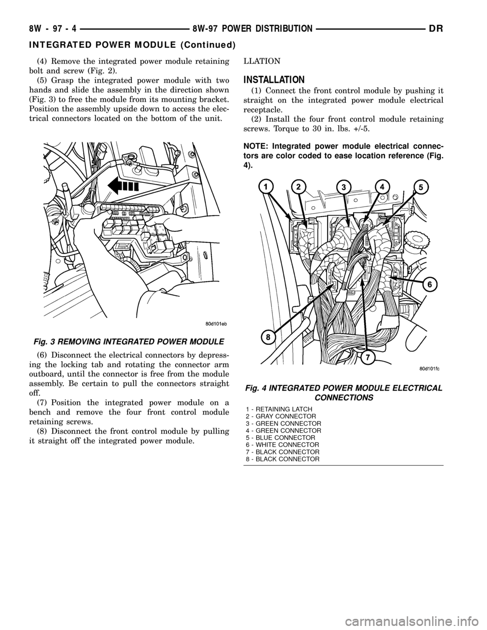
(4) Remove the integrated power module retaining
bolt and screw (Fig. 2).
(5) Grasp the integrated power module with two
hands and slide the assembly in the direction shown
(Fig. 3) to free the module from its mounting bracket.
Position the assembly upside down to access the elec-
trical connectors located on the bottom of the unit.
(6) Disconnect the electrical connectors by depress-
ing the locking tab and rotating the connector arm
outboard, until the connector is free from the module
assembly. Be certain to pull the connectors straight
off.
(7) Position the integrated power module on a
bench and remove the four front control module
retaining screws.
(8) Disconnect the front control module by pulling
it straight off the integrated power module.LLATION
INSTALLATION
(1) Connect the front control module by pushing it
straight on the integrated power module electrical
receptacle.
(2) Install the four front control module retaining
screws. Torque to 30 in. lbs. +/-5.
NOTE: Integrated power module electrical connec-
tors are color coded to ease location reference (Fig.
4).
Fig. 3 REMOVING INTEGRATED POWER MODULE
Fig. 4 INTEGRATED POWER MODULE ELECTRICAL
CONNECTIONS
1 - RETAINING LATCH
2 - GRAY CONNECTOR
3 - GREEN CONNECTOR
4 - GREEN CONNECTOR
5 - BLUE CONNECTOR
6 - WHITE CONNECTOR
7 - BLACK CONNECTOR
8 - BLACK CONNECTOR
8W - 97 - 4 8W-97 POWER DISTRIBUTIONDR
INTEGRATED POWER MODULE (Continued)
Page 1251 of 2627
REMOVAL
(1) Disconnect negative cable from battery.
(2)
Remove the resonator assemble and air inlet hose.
(3) Disconnect injector connectors and un-clip the
injector harness.
(4) Route injector harness in front of cylinder head
cover.
(5) Disconnect the left side breather tube and
remove the breather tube.
(6) Remove the cylinder head cover mounting bolts
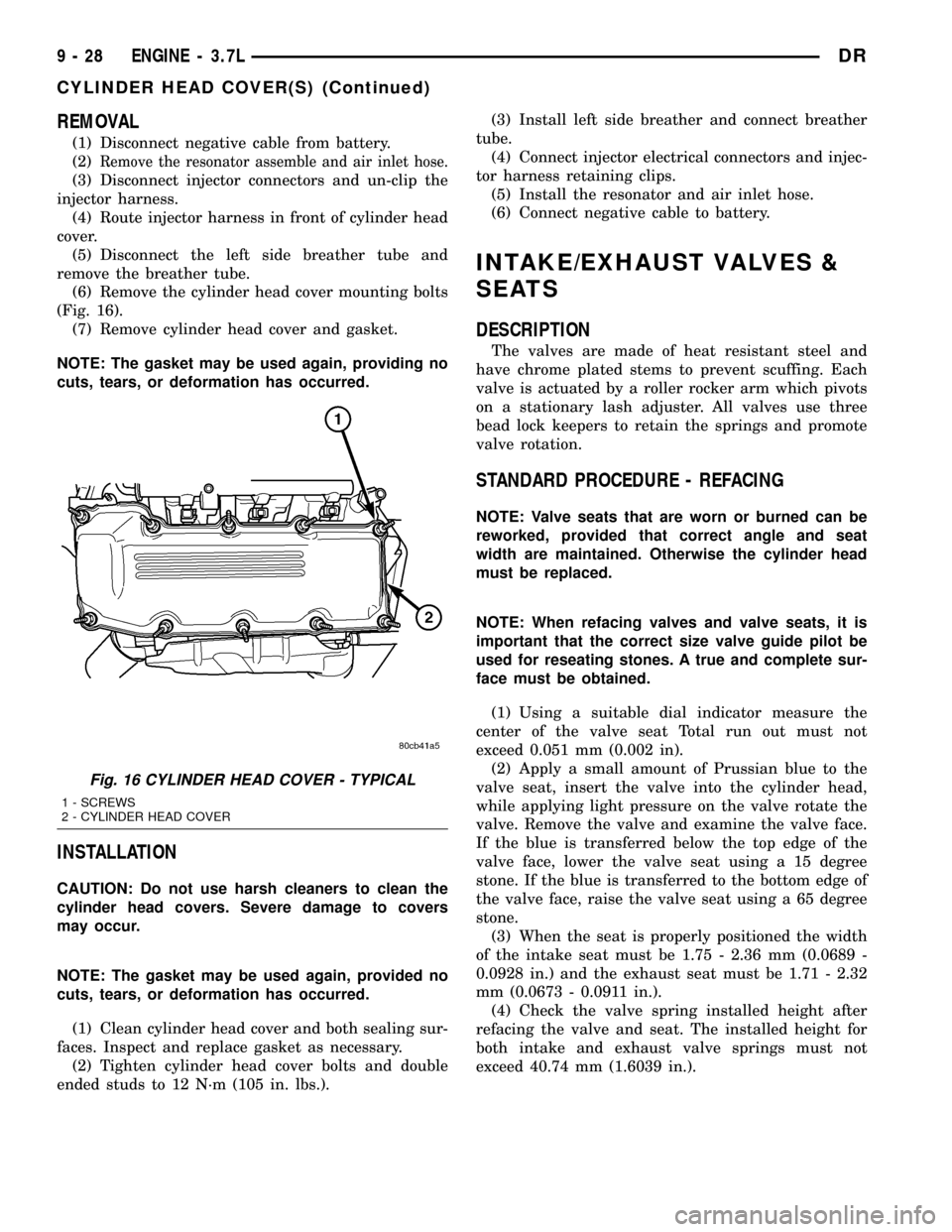
(Fig. 16).
(7) Remove cylinder head cover and gasket.
NOTE: The gasket may be used again, providing no
cuts, tears, or deformation has occurred.
INSTALLATION
CAUTION: Do not use harsh cleaners to clean the
cylinder head covers. Severe damage to covers
may occur.
NOTE: The gasket may be used again, provided no
cuts, tears, or deformation has occurred.
(1) Clean cylinder head cover and both sealing sur-
faces. Inspect and replace gasket as necessary.
(2) Tighten cylinder head cover bolts and double
ended studs to 12 N´m (105 in. lbs.).(3) Install left side breather and connect breather
tube.
(4) Connect injector electrical connectors and injec-
tor harness retaining clips.
(5) Install the resonator and air inlet hose.
(6) Connect negative cable to battery.
INTAKE/EXHAUST VALVES &
SEATS
DESCRIPTION
The valves are made of heat resistant steel and
have chrome plated stems to prevent scuffing. Each
valve is actuated by a roller rocker arm which pivots
on a stationary lash adjuster. All valves use three
bead lock keepers to retain the springs and promote
valve rotation.
STANDARD PROCEDURE - REFACING
NOTE: Valve seats that are worn or burned can be
reworked, provided that correct angle and seat
width are maintained. Otherwise the cylinder head
must be replaced.
NOTE: When refacing valves and valve seats, it is
important that the correct size valve guide pilot be
used for reseating stones. A true and complete sur-
face must be obtained.
(1) Using a suitable dial indicator measure the
center of the valve seat Total run out must not
exceed 0.051 mm (0.002 in).
(2) Apply a small amount of Prussian blue to the
valve seat, insert the valve into the cylinder head,
while applying light pressure on the valve rotate the
valve. Remove the valve and examine the valve face.
If the blue is transferred below the top edge of the
valve face, lower the valve seat using a 15 degree
stone. If the blue is transferred to the bottom edge of
the valve face, raise the valve seat using a 65 degree
stone.
(3) When the seat is properly positioned the width
of the intake seat must be 1.75 - 2.36 mm (0.0689 -
0.0928 in.) and the exhaust seat must be 1.71 - 2.32
mm (0.0673 - 0.0911 in.).
(4) Check the valve spring installed height after
refacing the valve and seat. The installed height for
both intake and exhaust valve springs must not
exceed 40.74 mm (1.6039 in.).
Fig. 16 CYLINDER HEAD COVER - TYPICAL
1 - SCREWS
2 - CYLINDER HEAD COVER
9 - 28 ENGINE - 3.7LDR
CYLINDER HEAD COVER(S) (Continued)
Page 1264 of 2627
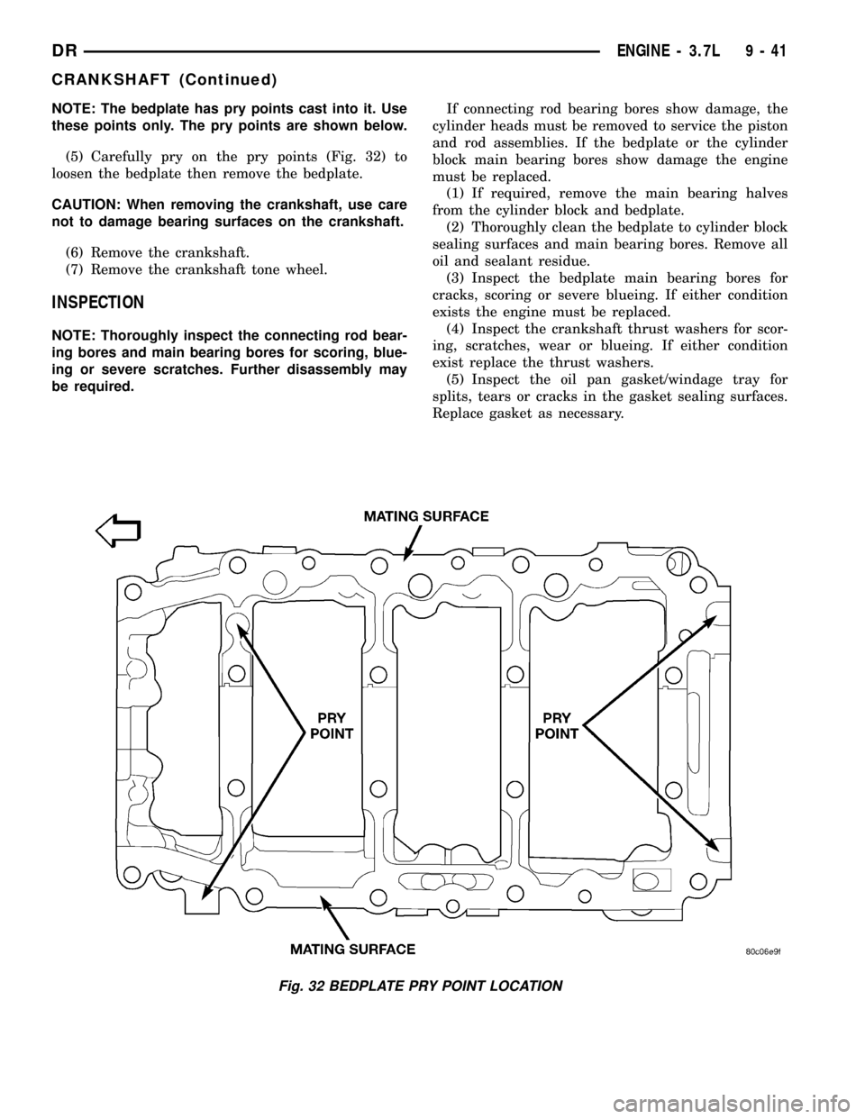
NOTE: The bedplate has pry points cast into it. Use
these points only. The pry points are shown below.
(5) Carefully pry on the pry points (Fig. 32) to
loosen the bedplate then remove the bedplate.
CAUTION: When removing the crankshaft, use care
not to damage bearing surfaces on the crankshaft.
(6) Remove the crankshaft.
(7) Remove the crankshaft tone wheel.
INSPECTION
NOTE: Thoroughly inspect the connecting rod bear-
ing bores and main bearing bores for scoring, blue-
ing or severe scratches. Further disassembly may
be required.If connecting rod bearing bores show damage, the
cylinder heads must be removed to service the piston
and rod assemblies. If the bedplate or the cylinder
block main bearing bores show damage the engine
must be replaced.
(1) If required, remove the main bearing halves
from the cylinder block and bedplate.
(2) Thoroughly clean the bedplate to cylinder block
sealing surfaces and main bearing bores. Remove all
oil and sealant residue.
(3) Inspect the bedplate main bearing bores for
cracks, scoring or severe blueing. If either condition
exists the engine must be replaced.
(4) Inspect the crankshaft thrust washers for scor-
ing, scratches, wear or blueing. If either condition
exist replace the thrust washers.
(5) Inspect the oil pan gasket/windage tray for
splits, tears or cracks in the gasket sealing surfaces.
Replace gasket as necessary.
Fig. 32 BEDPLATE PRY POINT LOCATION
DRENGINE - 3.7L 9 - 41
CRANKSHAFT (Continued)
Page 1300 of 2627
block. A large washer on the idler shaft bolt and the
rear flange of the idler shaft are used to control
sprocket thrust movement. Pressurized oil is routed
through the center of the idler shaft to provide lubri-
cation for the two bushings used in the idler sprocket
assembly.
There are two secondary drive chains, both are
roller type, one to drive the camshaft in each SOHC
cylinder head. There are no shaft speed changes in
the secondary chain drive system. Each secondary
chain drives a 26 tooth cam sprocket directly from
the 26 tooth sprocket on the idler sprocket assembly.
A fixed chain guide and a hydraulic oil damped ten-
sioner are used to maintain tension in each second-
ary chain system. The hydraulic tensioners for the
secondary chain systems are fed pressurized oil from
oil reservoir pockets in the block. Each tensioner
incorporates a controlled leak path through a device
known as a vent disc located in the nose of the piston
to manage chain loads. Each tensioner also has a
mechanical ratchet system that limits chain slack if
the tensioner piston bleeds down after engine shut
down. The tensioner arms and guides also utilize
nylon wear faces for low friction and long wear. The
secondary timing chains receive lubrication from a
small orifice in the tensioners. This orifice is pro-
tected from clogging by a fine mesh screen which is
located on the back of the hydraulic tensioners.
STANDARD PROCEDURE
MEASURING TIMING CHAIN WEAR
NOTE: This procedure must be performed with the
timing chain cover removed.
(1) Remove the timing chain cover (Refer to 9 -
ENGINE/VALVE TIMING/TIMING BELT/CHAIN
AND SPROCKETS - REMOVAL).
(2) To determine if the secondary timing chains
are worn, rotate the engine clockwise until maximum
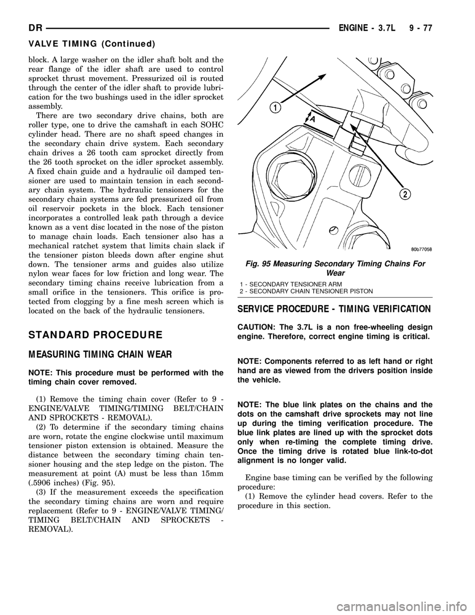
tensioner piston extension is obtained. Measure the
distance between the secondary timing chain ten-
sioner housing and the step ledge on the piston. The
measurement at point (A) must be less than 15mm
(.5906 inches) (Fig. 95).
(3) If the measurement exceeds the specification
the secondary timing chains are worn and require
replacement (Refer to 9 - ENGINE/VALVE TIMING/
TIMING BELT/CHAIN AND SPROCKETS -
REMOVAL).
SERVICE PROCEDURE - TIMING VERIFICATION
CAUTION: The 3.7L is a non free-wheeling design
engine. Therefore, correct engine timing is critical.
NOTE: Components referred to as left hand or right
hand are as viewed from the drivers position inside
the vehicle.
NOTE: The blue link plates on the chains and the
dots on the camshaft drive sprockets may not line
up during the timing verification procedure. The
blue link plates are lined up with the sprocket dots
only when re-timing the complete timing drive.
Once the timing drive is rotated blue link-to-dot
alignment is no longer valid.
Engine base timing can be verified by the following
procedure:
(1) Remove the cylinder head covers. Refer to the
procedure in this section.
Fig. 95 Measuring Secondary Timing Chains For
Wear
1 - SECONDARY TENSIONER ARM
2 - SECONDARY CHAIN TENSIONER PISTON
DRENGINE - 3.7L 9 - 77
VALVE TIMING (Continued)
Page 1355 of 2627
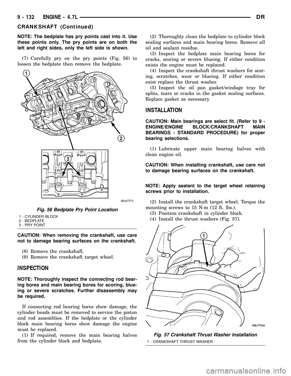
NOTE: The bedplate has pry points cast into it. Use
these points only. The pry points are on both the
left and right sides, only the left side is shown.
(7) Carefully pry on the pry points (Fig. 56) to
loosen the bedplate then remove the bedplate.
CAUTION: When removing the crankshaft, use care
not to damage bearing surfaces on the crankshaft.
(8) Remove the crankshaft.
(9) Remove the crankshaft target wheel.
INSPECTION
NOTE: Thoroughly inspect the connecting rod bear-
ing bores and main bearing bores for scoring, blue-
ing or severe scratches. Further disassembly may
be required.
If connecting rod bearing bores show damage, the
cylinder heads must be removed to service the piston
and rod assemblies. If the bedplate or the cylinder
block main bearing bores show damage the engine
must be replaced.
(1) If required, remove the main bearing halves
from the cylinder block and bedplate.(2) Thoroughly clean the bedplate to cylinder block
sealing surfaces and main bearing bores. Remove all
oil and sealant residue.
(3) Inspect the bedplate main bearing bores for
cracks, scoring or severe blueing. If either condition
exists the engine must be replaced.
(4) Inspect the crankshaft thrust washers for scor-
ing, scratches, wear or blueing. If either condition
exist replace the thrust washer.
(5) Inspect the oil pan gasket/windage tray for
splits, tears or cracks in the gasket sealing surfaces.
Replace gasket as necessary.
INSTALLATION
CAUTION: Main bearings are select fit. (Refer to 9 -
ENGINE/ENGINE BLOCK/CRANKSHAFT MAIN
BEARINGS - STANDARD PROCEDURE) for proper
bearing selections.
(1) Lubricate upper main bearing halves with
clean engine oil.
CAUTION: When installing crankshaft, use care not
to damage bearing surfaces on the crankshaft.
NOTE: Apply sealant to the target wheel retaining
screws prior to installation.
(2) Install the crankshaft target wheel. Torque the
mounting screws to 15 N´m (12 ft. lbs.).
(3) Position crankshaft in cylinder block.
(4) Install the thrust washers (Fig. 57).
Fig. 56 Bedplate Pry Point Location
1 - CYLINDER BLOCK
2 - BEDPLATE
3 - PRY POINT
Fig. 57 Crankshaft Thrust Washer Installation
1 - CRANKSHAFT THRUST WASHER
9 - 132 ENGINE - 4.7LDR
CRANKSHAFT (Continued)