1998 DODGE RAM 1500 ad blue
[x] Cancel search: ad bluePage 1362 of 2627
PISTON & CONNECTING ROD
DESCRIPTION
CAUTION: Do not use a metal stamp to mark con-
necting rods as damage may result, instead use ink
or a scratch awl.
The pistons are made of a high strength aluminum
alloy. The anodized top ring groove and crown has
been replaced with a coated top ring that is blue in
color on the bottom surface. Piston skirts are coated
with a solid lubricant (Molykote) to reduce friction
and provide scuff resistance. The connecting rods are
made of forged powdered metal, with a ªfractured
capº design. A pressed fit piston pin is used to attach
the piston and connecting rod.
STANDARD PROCEDURE - PISTON FITTING
(1) To correctly select the proper size piston, a cyl-
inder bore gauge, capable of reading in 0.003 mm (
.0001 in.) INCREMENTS is required. If a bore gauge
is not available, do not use an inside micrometer.
(2) Measure the inside diameter of the cylinder
bore at a point 38.0 mm (1.5 inches) below top of
bore. Start perpendicular (across or at 90 degrees) to
the axis of the crankshaft at point A and then take
an additional bore reading 90 degrees to that at point
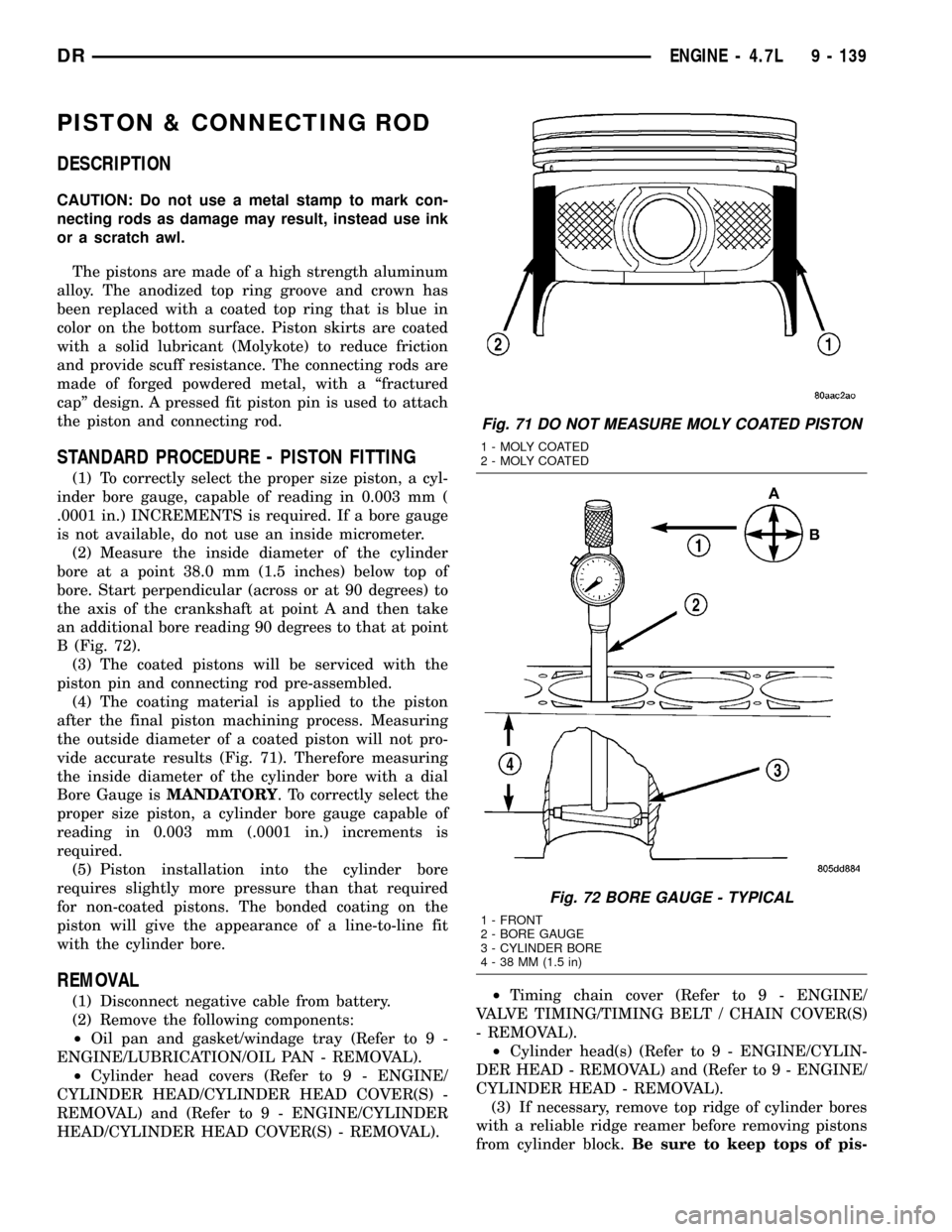
B (Fig. 72).
(3) The coated pistons will be serviced with the
piston pin and connecting rod pre-assembled.
(4) The coating material is applied to the piston
after the final piston machining process. Measuring
the outside diameter of a coated piston will not pro-
vide accurate results (Fig. 71). Therefore measuring
the inside diameter of the cylinder bore with a dial
Bore Gauge isMANDATORY. To correctly select the
proper size piston, a cylinder bore gauge capable of
reading in 0.003 mm (.0001 in.) increments is
required.
(5) Piston installation into the cylinder bore
requires slightly more pressure than that required
for non-coated pistons. The bonded coating on the
piston will give the appearance of a line-to-line fit
with the cylinder bore.
REMOVAL
(1) Disconnect negative cable from battery.
(2) Remove the following components:
²Oil pan and gasket/windage tray (Refer to 9 -
ENGINE/LUBRICATION/OIL PAN - REMOVAL).
²Cylinder head covers (Refer to 9 - ENGINE/
CYLINDER HEAD/CYLINDER HEAD COVER(S) -
REMOVAL) and (Refer to 9 - ENGINE/CYLINDER
HEAD/CYLINDER HEAD COVER(S) - REMOVAL).²Timing chain cover (Refer to 9 - ENGINE/
VALVE TIMING/TIMING BELT / CHAIN COVER(S)
- REMOVAL).
²Cylinder head(s) (Refer to 9 - ENGINE/CYLIN-
DER HEAD - REMOVAL) and (Refer to 9 - ENGINE/
CYLINDER HEAD - REMOVAL).
(3) If necessary, remove top ridge of cylinder bores
with a reliable ridge reamer before removing pistons
from cylinder block.Be sure to keep tops of pis-
Fig. 71 DO NOT MEASURE MOLY COATED PISTON
1 - MOLY COATED
2 - MOLY COATED
Fig. 72 BORE GAUGE - TYPICAL
1 - FRONT
2 - BORE GAUGE
3 - CYLINDER BORE
4 - 38 MM (1.5 in)
DRENGINE - 4.7L 9 - 139
Page 1390 of 2627
sprocket assembly. A fixed chain guide and a hydrau-
lic oil damped tensioner are used to maintain tension
in each secondary chain system. The hydraulic ten-
sioners for the secondary chain systems are fed pres-
surized oil from oil reservoir pockets in the block.
Each tensioner also has a mechanical ratchet system
that limits chain slack if the tensioner piston bleeds
down after engine shut down. The tensioner arms
and guides also utilize nylon wear faces for low fric-
tion and long wear. The secondary timing chains
receive lubrication from a small orifice in the ten-
sioners. This orifice is protected from clogging by a
fine mesh screen which is located on the back of the
hydraulic tensioners.
STANDARD PROCEDURE
STANDARD PROCEDUREÐMEASURING
TIMING CHAIN WEAR
NOTE: This procedure must be performed with the
timing chain cover removed.
(1) Remove the timing chain cover. (Refer to 9 -
ENGINE/VALVE TIMING/TIMING BELT / CHAIN
COVER(S) - REMOVAL).
(2) To determine if the secondary timing chains
are worn, rotate the engine clockwise until maximum
tensioner piston extension is obtained. Measure the
distance between the secondary timing chain ten-
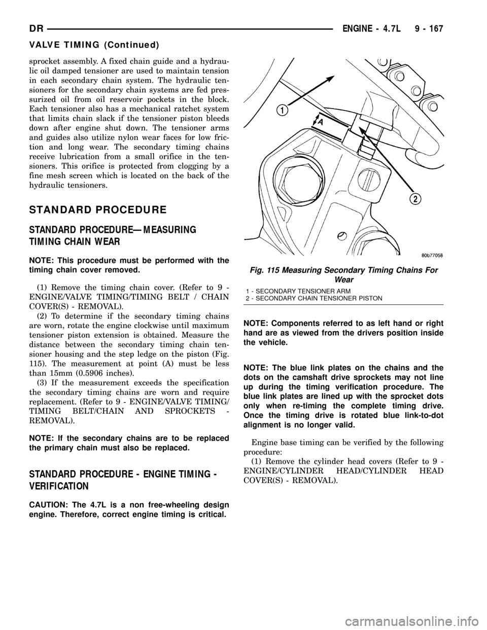
sioner housing and the step ledge on the piston (Fig.
115). The measurement at point (A) must be less
than 15mm (0.5906 inches).
(3) If the measurement exceeds the specification
the secondary timing chains are worn and require
replacement. (Refer to 9 - ENGINE/VALVE TIMING/
TIMING BELT/CHAIN AND SPROCKETS -
REMOVAL).
NOTE: If the secondary chains are to be replaced
the primary chain must also be replaced.
STANDARD PROCEDURE - ENGINE TIMING -
VERIFICATION
CAUTION: The 4.7L is a non free-wheeling design
engine. Therefore, correct engine timing is critical.NOTE: Components referred to as left hand or right
hand are as viewed from the drivers position inside
the vehicle.
NOTE: The blue link plates on the chains and the
dots on the camshaft drive sprockets may not line
up during the timing verification procedure. The
blue link plates are lined up with the sprocket dots
only when re-timing the complete timing drive.
Once the timing drive is rotated blue link-to-dot
alignment is no longer valid.
Engine base timing can be verified by the following
procedure:
(1) Remove the cylinder head covers (Refer to 9 -
ENGINE/CYLINDER HEAD/CYLINDER HEAD
COVER(S) - REMOVAL).
Fig. 115 Measuring Secondary Timing Chains For
Wear
1 - SECONDARY TENSIONER ARM
2 - SECONDARY CHAIN TENSIONER PISTON
DRENGINE - 4.7L 9 - 167
VALVE TIMING (Continued)
Page 1425 of 2627
INTAKE/EXHAUST VALVES &
SEATS
DESCRIPTION
DESCRIPTION - VALVE GUIDES
The valve guides are made of powered metal and
are pressed into the cylinder head. The guides are
not replaceable or serviceable, and valve guide ream-
ing is not recommended. If the guides are worn
beyond acceptable limits, replace the cylinder heads.
DESCRIPTION
Both the intake and exhaust valves are made of
steel. The intake valve is 50.93 mm (2.00 inches) in
diameter and the exhaust valve is 39.53 mm (1.55
inches) in diameter. All valves use three bead lock
keepers to retain the springs and promote valve rota-
tion.
STANDARD PROCEDURE - REFACING
NOTE: Valve seats that are worn or burned can be
reworked, provided that correct angle and seat
width are maintained. Otherwise the cylinder head
must be replaced.
NOTE: When refacing valves and valve seats, it is
important that the correct size valve guide pilot be
used for reseating stones. A true and complete sur-
face must be obtained.
(1) Using a suitable dial indicator measure the
center of the valve seat Total run out must not
exceed 0.051 mm (0.002 in).
(2) Apply a small amount of Prussian blue to the
valve seat, insert the valve into the cylinder head,
while applying light pressure on the valve rotate the
valve. Remove the valve and examine the valve face.
If the blue is transferred below the top edge of the
valve face, lower the valve seat using a 15 degree
stone. If the blue is transferred to the bottom edge of
the valve face, raise the valve seat using a 65 degree
stone.
(3) When the seat is properly positioned the width
of the intake seat must be 1.018 - 1.62 mm (0.0464 -
0.0637 in.) and the exhaust seat must be 1.48 - 1.92
mm (0.058 - 0.075 in.).
(4) Check the valve spring installed height after
refacing the valve and seat. The installed height for
both intake and exhaust valve springs must not
exceed 46.0 mm (1.81 in.).
VALVE FACE AND VALVE SEAT ANGLE CHART
DESCRIPTION SPECIFICATION
SEAT WIDTH
INTAKE 1.018 - 1.62 mm
(0.0464 - 0.0637 in.)
EXHAUST 1.48 - 1.92 mm
(0.058 - 0.075 in.)
FACE ANGLE
(INT. AND EXT.) 45É - 45
1¤2É
SEAT ANGLE
(INT. AND EXT.) 44
1¤2É - 45É
(5)
The valve seat must maintain an angle of 44.5 ±
45.0 degrees angle.
(6) The valve face must maintain a face angle of
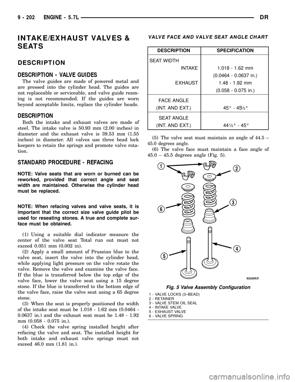
45.0 ± 45.5 degrees angle (Fig. 5).
Fig. 5 Valve Assembly Configuration
1 - VALVE LOCKS (3±BEAD)
2 - RETAINER
3 - VALVE STEM OIL SEAL
4 - INTAKE VALVE
5 - EXHAUST VALVE
6 - VALVE SPRING
9 - 202 ENGINE - 5.7LDR
Page 1461 of 2627
EXCESSIVE BLUE SMOKE
POSSIBLE CAUSE CORRECTION
Dirty air cleaner or restricted turbocharger intake duct. Check Filter MinderTat air filter housing. (Refer to 9 -
ENGINE/AIR INTAKE SYSTEM/AIR CLEANER
ELEMENT - REMOVAL).
Air leak in boost system between turbocharger
compressor outlet and intake manifold.Service air charge system..
Obstruction in exhaust manifold. Remove exhaust manifold and inspect for blockage
(Refer to 9 - ENGINE/MANIFOLDS/EXHAUST
MANIFOLD - REMOVAL).
Restricted turbocharger drain tube. Remove turbocharger drain tube and remove
obstruction.
Crankcase ventilation system plugged. Inspect crankcase ventilation system for function
Valve seals are worn, brittle, or improperly installed. Replace valve stem oil seals (Refer to 9 - ENGINE/
CYLINDER HEAD/INTAKE/EXHAUST VALVES &
SEATS - REMOVAL).
Valve stems and/or guides are worn. Remove valves and inspect valves and guides. (Refer
to 9 - ENGINE/CYLINDER HEAD/INTAKE/EXHAUST
VALVES & SEATS - STANDARD PROCEDURE).
Broken or Improperly installed piston rings. Tear down engine and inspect piston rings.
Excessive piston ring end gap. Remove pistons and measure piston ring end gap
(Refer to 9 - ENGINE/ENGINE BLOCK/PISTON RINGS
- STANDARD PROCEDURE).
Excessive cylinder bore wear and taper. Remove pistons and measure cylinder bore wear and
taper (Refer to 9 - ENGINE/ENGINE BLOCK -
STANDARD PROCEDURE).
Cylinder damage. Remove pistons and inspect cylinder bore for cracks or
porosity. Repair with cylinder liner if necessary. (Refer
to 9 - ENGINE/ENGINE BLOCK - STANDARD
PROCEDURE).
Piston damage. Remove pistons and inspect for cracks, holes. Measure
piston for out-of-round and taper (Refer to 9 -
ENGINE/ENGINE BLOCK/PISTON & CONNECTING
ROD - INSPECTION).
Turbocharger failure. (Refer to 11 - EXHAUST SYSTEM/TURBOCHARGER
SYSTEM/TURBOCHARGER - INSPECTION).
9 - 238 ENGINE 5.9L DIESELDR
ENGINE 5.9L DIESEL (Continued)
Page 1621 of 2627

The fuel heater element and fuel heater relay
are not computer controlled.
The heater element operates on 12 volts, 300 watts
at 0 degrees F.
DIAGNOSIS AND TESTING - FUEL HEATER
The fuel heater is used to prevent diesel fuel from
waxing during cold weather operation.
NOTE: The fuel heater element, fuel heater relay
and fuel heater temperature sensor are not con-
trolled by the Engine Control Module (ECM).
A malfunctioning fuel heater can cause a wax
build-up in the fuel filter/water separator. Wax
build-up in the filter/separator can cause engine
starting problems and prevent the engine from rev-
ving up. It can also cause blue or white fog-like
exhaust. If the heater is not operating in cold tem-
peratures, the engine may not operate due to fuel
waxing.
The fuel heater assembly is located on the side of
fuel filter housing.
The heater assembly is equipped with a built-in
fuel temperature sensor (thermostat) that senses fuel
temperature. When fuel temperature drops below 45
degrees 8 degrees F, the sensor allows current to
flow to built-in heater element to warm fuel. When
fuel temperature rises above 75 degrees 8 degrees
F, the sensor stops current flow to heater element
(circuit is open).
Voltage to operate fuel heater element is supplied
from ignition switch, through fuel heater relay (also
refer to Fuel Heater Relay), to fuel temperature sen-
sor and on to fuel heater element.
The heater element operates on 12 volts, 300 watts
at 0 degrees F. As temperature increases, power
requirements decrease.
A minimum of 7 volts is required to operate the
fuel heater. The resistance value of the heater ele-
ment is less than 1 ohm (cold) and up to 1000 ohms
warm.
TESTING
(1) Disconnect electrical connector from thermostat
(Fig. 3).
Ambient temperature must be below the circuit
close temperature. If necessary, induce this ambient
temperature by placing ice packs on thermostat to
produce an effective ambient temperature below cir-
cuit close temperature.
Measure resistance across two pins. Operating
range is 0.3 Ð 0.45 Ohms.
(2) If resistance is out of range, remove thermostat
and check resistance across terminal connections of
heater. The heater can be checked at room tempera-
ture. Operating range is 0.3 - 0.45 Ohms.(3) Replace heater if resistance is not within oper-
ating range.
(4) If heater is within operating range, replace
heater thermostat.
REMOVAL
REMOVAL/INSTALLATION
The fuel heater/element/sensor assembly is located
inside of the fuel filter housing. Refer to Fuel Filter/
Water Separator Removal/Installation for procedures.
FUEL HEATER RELAY
DESCRIPTION
The fuel heater relay is located in Power Distribu-
tion Center (PDC) (Fig. 5). Refer to label on inside of
PDC cover for relay location.
OPERATION
Battery voltage to operate the fuel heater element
is supplied from the ignition switch through the fuel
heater relay.The fuel heater element and fuel
heater relay are not computer controlled.
REMOVAL
The fuel heater relay is located in the Power Dis-
tribution Center (PDC) (Fig. 6). Refer to label under
PDC cover for relay location.
(1) Remove PDC cover.
(2) Remove relay from PDC.
Fig. 5 POWER DISTRIBUTION CENTER LOCATION
1 - CLIP
2 - BATTERY
3 - TRAY
4 - NEGATIVE CABLE
5 - POSITIVE CABLE
6 - CLIP
7 - FENDER INNER SHIELD
8 - POWER DISTRIBUTION CENTER
14 - 52 FUEL DELIVERY - DIESELDR
FUEL HEATER (Continued)
Page 2368 of 2627
PAINT
TABLE OF CONTENTS
page page
PAINT
SPECIFICATIONS - PAINT CODES..........73
PAINT CODE
DESCRIPTION.........................73
BASECOAT/CLEARCOAT FINISH
DESCRIPTION.........................73PAINT TOUCH-UP
DESCRIPTION.........................74
STANDARD PROCEDURE - PAINT TOUCH-UP . 74
FINESSE SANDING/BUFFING & POLISHING
DESCRIPTION.........................74
PAINT
SPECIFICATIONS - PAINT CODES
NOTE: Because of late model changes to the avail-
able paint colors (Refer to VEHICLE DATA/VEHICLE
INFORMATION/VEHICLE CERTIFICATION LABEL -
DESCRIPTION) or (Refer to VEHICLE DATA/VEHI-
CLE INFORMATION/BODY CODE PLATE - DESCRIP-
TION) for the correct paint codes for each vehicle.
(Refer to 23 - BODY/PAINT/PAINT CODE - DESCRIP-
TION)
EXTERIOR COLORS
EXTERIOR COLOR DAIMLERCHRYSLER
CODE
Deep Molten Red
PearlcoatBR8
Flame Red Clearcoat PR4
Light Almond Pearl
Metallic ClearcoatZKJ
Atlantic Blue Pearlcoat ZBJ
Patriot Blue Pearlcoat WBT/WB7
Graphite Metallic
ClearcoatZDR
Bright Silver Metallic
ClearcoatWSB/WS2
Black Clearcoat DX8
Bright White Clearcoat GW7
Timberline Green AGW
INTERIOR COLORS
INTERIOR COLOR DAIMLERCHRYSLER
CODE
Taupe L5
Dark Slate Gray DV
PAINT CODE
DESCRIPTION
Exterior vehicle body colors are identified on the
Vehicle Certification Label (Refer to VEHICLE
DATA/VEHICLE INFORMATION/VEHICLE CERTI-
FICATION LABEL - DESCRIPTION) or the Body
Code Plate (Refer to VEHICLE DATA/VEHICLE
INFORMATION/BODY CODE PLATE - DESCRIP-
TION). The first digit of the paint code listed on the
vehicle indicates the sequence of application, i.e.: P =
primary coat, Q = secondary coat. The color names
provided in the Paint and Trim Code Description
chart are the color names used on most repair prod-
uct containers. (Refer to 23 - BODY/PAINT - SPECI-
FICATIONS)
BASECOAT/CLEARCOAT
FINISH
DESCRIPTION
The original equipment finish is a multi step pro-
cess that involves cleaning, applying electro de-posi-
tion (E-coat), anti-chip primer, basecoat, and
clearcoat steps.
On most vehicles a two-part paint application
(basecoat/clearcoat) is used. Color paint that is
applied to primer is called basecoat. The clear coat
protects the basecoat from ultraviolet light and pro-
vides a durable high-gloss finish.
DRPAINT 23 - 73
Page 2533 of 2627
STANDARD PROCEDURE - REFRIGERANT
SYSTEM SERVICE EQUIPMENT
WARNING: EYE PROTECTION MUST BE WORN
WHEN SERVICING AN AIR CONDITIONING REFRIG-
ERANT SYSTEM. TURN OFF (ROTATE CLOCKWISE)
ALL VALVES ON THE EQUIPMENT BEING USED
BEFORE CONNECTING TO, OR DISCONNECTING
FROM THE REFRIGERANT SYSTEM. FAILURE TO
OBSERVE THESE WARNINGS MAY RESULT IN PER-
SONAL INJURY.
WARNING: REVIEW THE WARNINGS AND CAU-
TIONS IN THE FRONT OF THIS SECTION BEFORE
PERFORMING THE FOLLOWING OPERATION (Refer
to 24 - HEATING & AIR CONDITIONING/PLUMBING -
WARNING) and (Refer to 24 - HEATING & AIR CON-
DITIONING/PLUMBING - CAUTION).
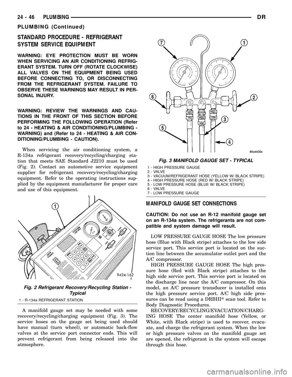
When servicing the air conditioning system, a
R-134a refrigerant recovery/recycling/charging sta-
tion that meets SAE Standard J2210 must be used
(Fig. 2). Contact an automotive service equipment
supplier for refrigerant recovery/recycling/charging
equipment. Refer to the operating instructions sup-
plied by the equipment manufacturer for proper care
and use of this equipment.
A manifold gauge set may be needed with some
recovery/recycling/charging equipment (Fig. 3). The
service hoses on the gauge set being used should
have manual (turn wheel), or automatic back-flow
valves at the service port connector ends. This will
prevent refrigerant from being released into the
atmosphere.
MANIFOLD GAUGE SET CONNECTIONS
CAUTION: Do not use an R-12 manifold gauge set
on an R-134a system. The refrigerants are not com-
patible and system damage will result.
LOW PRESSURE GAUGE HOSE The low pressure
hose (Blue with Black stripe) attaches to the low side
service port. This service port is located on the suc-
tion line between the accumulator outlet port and the
A/C compressor.
HIGH PRESSURE GAUGE HOSE The high pres-
sure hose (Red with Black stripe) attaches to the
high side service port. This service port is located on
the discharge line near the A/C compressor. On this
model, an A/C pressure transducer is installed onto
the high pressure service port. A/C high side pres-
sures can be read using a DRBIIItscan tool. Refer to
Body Diagnostic Procedures.
RECOVERY/RECYCLING/EVACUATION/CHARG-
ING HOSE The center manifold hose (Yellow, or
White, with Black stripe) is used to recover, evacu-
ate, and charge the refrigerant system. When the low
or high pressure valves on the manifold gauge set
are opened, the refrigerant in the system will escape
through this hose.
Fig. 2 Refrigerant Recovery/Recycling Station -
Typical
1 - R-134a REFRIGERANT STATION
Fig. 3 MANIFOLD GAUGE SET - TYPICAL
1 - HIGH PRESSURE GAUGE
2 - VALVE
3 - VACUUM/REFRIGERANT HOSE (YELLOW W/ BLACK STRIPE)
4 - HIGH PRESSURE HOSE (RED W/ BLACK STRIPE)
5 - LOW PRESSURE HOSE (BLUE W/ BLACK STRIPE)
6 - VALVE
7 - LOW PRESSURE GAUGE
24 - 46 PLUMBINGDR
PLUMBING (Continued)