1998 DODGE RAM 1500 Camshaft removal
[x] Cancel search: Camshaft removalPage 1254 of 2627
ROCKER ARM
DESCRIPTION
The rocker arms are steel stampings with an inte-
gral roller bearing. The rocker arms incorporate a 2.8
mm (0.11 inch) oil hole in the lash adjuster socket for
roller and camshaft lubrication.
REMOVAL
NOTE: Disconnect the battery negative cable to pre-
vent accidental starter engagement.
(1) Remove the cylinder head cover (Refer to 9 -
ENGINE/CYLINDER HEAD/CYLINDER HEAD
COVER(S) - REMOVAL).
(2) For rocker arm removal on cylinder No. 4,
Rotate the crankshaft until cylinder No. 1 is at BDC
intake stroke.
(3) For rocker arm removal on cylinder No. 1,
Rotate the crankshaft until cylinder No. 1 is at BDC
combustion stroke.
(4) For rocker arm removal on cylinders No. 3 and
No. 5, Rotate the crankshaft until cylinder No. 1 is at
TDC exhaust stroke.
(5) For rocker arm removal on cylinders No. 2 and
No. 6, Rotate the crankshaft until cylinder No. 1 is at
TDC ignition stroke.
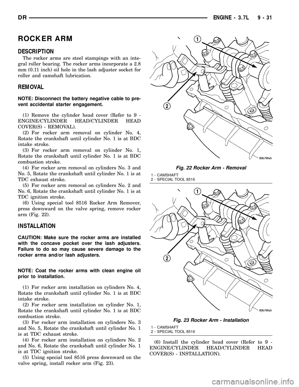
(6) Using special tool 8516 Rocker Arm Remover,
press downward on the valve spring, remove rocker
arm (Fig. 22).
INSTALLATION
CAUTION: Make sure the rocker arms are installed
with the concave pocket over the lash adjusters.
Failure to do so may cause severe damage to the
rocker arms and/or lash adjusters.
NOTE: Coat the rocker arms with clean engine oil
prior to installation.
(1) For rocker arm installation on cylinders No. 4,
Rotate the crankshaft until cylinder No. 1 is at BDC
intake stroke.
(2) For rocker arm installation on cylinder No. 1,
Rotate the crankshaft until cylinder No. 1 is at BDC
combustion stroke.
(3) For rocker arm installation on cylinders No. 3
and No. 5, Rotate the crankshaft until cylinder No. 1
is at TDC exhaust stroke.
(4) For rocker arm installation on cylinders No. 2
and No. 6, Rotate the crankshaft until cylinder No. 1
is at TDC ignition stroke.
(5) Using special tool 8516 press downward on the
valve spring, install rocker arm (Fig. 23).(6) Install the cylinder head cover (Refer to 9 -
ENGINE/CYLINDER HEAD/CYLINDER HEAD
COVER(S) - INSTALLATION).
Fig. 22 Rocker Arm - Removal
1 - CAMSHAFT
2 - SPECIAL TOOL 8516
Fig. 23 Rocker Arm - Installation
1 - CAMSHAFT
2 - SPECIAL TOOL 8516
DRENGINE - 3.7L 9 - 31
Page 1256 of 2627
(6) Air ingested into oil due to broken or cracked
oil pump pick up.
(7) Worn valve guides.
(8) Rocker arm ears contacting valve spring
retainer.
(9) Rocker arm loose, adjuster stuck or at maxi-
mum extension and still leaves lash in the system.
(10) Oil leak or excessive cam bore wear in cylin-
der head.
(11) Faulty lash adjuster.
a. Check lash adjusters for sponginess while
installed in cylinder head and cam on camshaft at
base circle. Depress part of rocker arm over adjuster.
Normal adjusters should feel very firm. Spongy
adjusters can be bottomed out easily.
b. Remove suspected lash adjusters, and replace.
c. Before installation, make sure adjusters are at
least partially full of oil. This can be verified by little
or no plunger travel when lash adjuster is depressed.
REMOVAL
(1) Disconnect battery negative cable.
(2) Raise the vehicle on a hoist.
(3) Disconnect the exhaust pipe at the right side
exhaust manifold.
(4) Drain the engine coolant(Refer to 7 - COOL-
ING - STANDARD PROCEDURE).
(5) Lower the vehicle.
(6) Remove the intake manifold(Refer to 9 -
ENGINE/MANIFOLDS/INTAKE MANIFOLD -
REMOVAL).
(7) Remove the cylinder head cover(Refer to 9 -
ENGINE/CYLINDER HEAD - REMOVAL).
(8) Remove the fan shroud(Refer to 7 - COOLING/
ENGINE/RADIATOR FAN - REMOVAL).
(9) Remove oil fill housing from cylinder head.
(10) Remove accessory drive belt(Refer to 7 -
COOLING/ACCESSORY DRIVE/DRIVE BELTS -
REMOVAL).
(11) Rotate the crankshaft until the damper timing
mark is aligned with TDC indicator mark.
(12) Verify the V6 mark on the camshaft sprocket
is at the 12 o'clock position. Rotate the crankshaft
one turn if necessary.
(13) Remove the crankshaft damper(Refer to 9 -
ENGINE/ENGINE BLOCK/VIBRATION DAMPER -
REMOVAL).
(14) Remove the timing chain cover(Refer to 9 -
ENGINE/VALVE TIMING/TIMING BELT / CHAIN
COVER(S) - REMOVAL).
(15) Lock the secondary timing chains to the idler
sprocket using Special Tool 8429 Timing Chain Hold-
ing Fixture.NOTE: Mark the secondary timing chain prior to
removal to aid in installation.
(16) Mark the secondary timing chain, one link on
each side of the V6 mark on the camshaft drive gear.
(17) Remove the right side secondary chain ten-
sioner(Refer to 9 - ENGINE/VALVE TIMING/TIM-
ING BELT/CHAIN AND SPROCKETS - REMOVAL).
(18) Remove the cylinder head access plug.
(19) Remove the right side secondary chain
guide(Refer to 9 - ENGINE/VALVE TIMING/TIMING
BELT/CHAIN AND SPROCKETS - REMOVAL).
CAUTION: The nut on the right side camshaft
sprocket should not be removed for any reason, as
the sprocket and camshaft sensor target wheel is
serviced as an assembly. If the nut was removed,
torque nut to 5 N´m (44 in. lbs.).
(20) Remove the retaining bolt and the camshaft
drive gear.
CAUTION: Do not allow the engine to rotate. severe
damage to the valve train can occur.
CAUTION: Do not overlook the four smaller bolts at
the front of the cylinder head. Do not attempt to
remove the cylinder head without removing these
four bolts.
CAUTION: Do not hold or pry on the camshaft tar-
get wheel for any reason. A damaged target wheel
can result in a vehicle no start condition.
NOTE: The cylinder head is attached to the cylinder
block with twelve bolts.
(21) Remove the cylinder head retaining bolts.
(22) Remove the cylinder head and gasket. Discard
the gasket.
CAUTION: Do not lay the cylinder head on its gas-
ket sealing surface, do to the design of the cylinder
head gasket any distortion to the cylinder head
sealing surface may prevent the gasket from prop-
erly sealing resulting in leaks.
DRENGINE - 3.7L 9 - 33
CYLINDER HEAD - RIGHT (Continued)
Page 1258 of 2627
CAUTION: The nut on the right side camshaft
sprocket should not be removed for any reason, as
the sprocket and camshaft sensor target wheel is
serviced as an assembly. If the nut was removed,
torque nut to 5 NM ( 60 in. lbs.).
(7) Position the secondary chain onto the camshaft
drive gear, making sure one marked chain link is on
either side of the V6 mark on the gear then using
Special Tool 8428 Camshaft Wrench, position the
gear onto the camshaft.
CAUTION: Remove excess oil from camshaft
sprocket retaining bolt before reinstalling bolt. Fail-
ure to do so may cause over-torquing of bolt result-
ing in bolt failure.
(8) Install the camshaft drive gear retaining bolt.
(9) Install the right side secondary chain guide(Re-
fer to 9 - ENGINE/VALVE TIMING/TIMING BELT/
CHAIN AND SPROCKETS - INSTALLATION).
(10) Install the cylinder head access plug.
(11) Re-set and install the right side secondary
chain tensioner(Refer to 9 - ENGINE/VALVE TIM-
ING/TIMING BELT/CHAIN AND SPROCKETS -
INSTALLATION).
(12) Remove Special Tool 8429.
(13) Install the timing chain cover(Refer to 9 -
ENGINE/VALVE TIMING/TIMING BELT / CHAIN
COVER(S) - REMOVAL).
(14) Install the crankshaft damper(Refer to 9 -
ENGINE/ENGINE BLOCK/VIBRATION DAMPER -
INSTALLATION). Tighten damper bolt 175 N´m (130
Ft. Lbs.).
(15) Install accessory drive belt(Refer to 7 - COOL-
ING/ACCESSORY DRIVE/DRIVE BELTS - INSTAL-
LATION).
(16) Install the fan shroud(Refer to 7 - COOLING/
ENGINE/RADIATOR FAN - INSTALLATION).
(17) Install the cylinder head cover(Refer to 9 -
ENGINE/CYLINDER HEAD/CYLINDER HEAD
COVER(S) - INSTALLATION).
(18) Install the intake manifold(Refer to 9 -
ENGINE/MANIFOLDS/INTAKE MANIFOLD -
INSTALLATION).
(19) Install oil fill housing onto cylinder head.
(20) Refill the cooling system(Refer to 7 - COOL-
ING - STANDARD PROCEDURE).
(21) Raise the vehicle.
(22) Install the exhaust pipe onto the right
exhaust manifold.
(23) Lower the vehicle.
(24) Reconnect battery negative cable.
(25) Start the engine and check for leaks.CAMSHAFT(S)
DESCRIPTION
The camshafts consist of powdered metal steel
lobes which are sinter-bonded to a steel tube. Four
bearing journals are machined into the camshaft.
Camshaft end play is controlled by two thrust walls
that border the nose piece journal. Engine oil enters
the hollow camshafts at the third journal and lubri-
cates every intake lobe rocker through a drilled pas-
sage in the intake lobe.
REMOVAL
CAUTION: When the timing chain is removed and
the cylinder heads are still installed, DO NOT force-
fully rotate the camshafts or crankshaft indepen-
dently of each other. Severe valve and/or piston
damage can occur.
CAUTION: When removing the cam sprocket, timing
chains or camshaft, Failure to use special tool 8379
will result in hydraulic tensioner ratchet over exten-
sion, Requiring timing chain cover removal to re-set
the tensioner ratchet.
(1) Remove the cylinder head cover(Refer to 9 -
ENGINE/CYLINDER HEAD/CYLINDER HEAD
COVER(S) - REMOVAL).
(2) Set engine to TDC cylinder No. 1, camshaft
sprocket V6 marks at the 12 o'clock position.
(3) Mark one link on the secondary timing chain
on both sides of the V6 mark on the camshaft
sprocket to aid in installation.
CAUTION: Do not hold or pry on the camshaft tar-
get wheel for any reason, Severe damage will occur
to the target wheel. A damaged target wheel could
cause a vehicle no start condition.
(4) Loosen butDO NOTremove the camshaft
sprocket retaining bolt. Leave bolt snug against
sprocket.
NOTE: The timing chain tensioners must be
secured prior to removing the camshaft sprockets.
Failure to secure tensioners will allow the tension-
ers to extend, requiring timing chain cover removal
in order to reset tensioners.
CAUTION: Do not force wedge past the narrowest
point between the chain strands. Damage to the
tensioners may occur.
DRENGINE - 3.7L 9 - 35
CYLINDER HEAD - RIGHT (Continued)
Page 1259 of 2627
(5) Position Special Tool 8379 timing chain wedge
between the timing chain strands. Tap the tool to
securely wedge the timing chain against the ten-
sioner arm and guide.
(6) Remove the camshaft position sensor.
(7) Hold the camshaft with Special Tool 8428 Cam-
shaft Wrench, while removing the camshaft sprocket
bolt and sprocket.
(8) Starting at the outside working inward, loosen
the camshaft bearing cap retaining bolts 1/2 turn at
a time. Repeat until all load is off the bearing caps.
CAUTION: DO NOT STAMP OR STRIKE THE CAM-
SHAFT BEARING CAPS. SEVERE DAMAGE WILL
OCCUR TO THE BEARING CAPS.
NOTE: When the camshaft is removed the rocker
arms may slide downward, mark the rocker arms
before removing camshaft.
(9) Remove the camshaft bearing caps and the
camshaft.
INSTALLATION
(1) Lubricate camshaft journals with clean engine
oil.
NOTE: Position the right side camshaft so that the
camshaft sprocket dowel is near the 10 o'clock
position, This will place the camshaft at the neutral
position easing the installation of the camshaft
bearing caps.
(2) Position the camshaft into the cylinder head.
(3) Install the camshaft bearing caps, hand tighten
the retaining bolts.
NOTE: Caps should be installed so that the
stamped numbers on the caps are in numerical
order, ( 1 thru 4 ) from the front to the rear of the
engine. All caps should be installed so that the
stamped arrows on the caps point toward the front
of the engine.
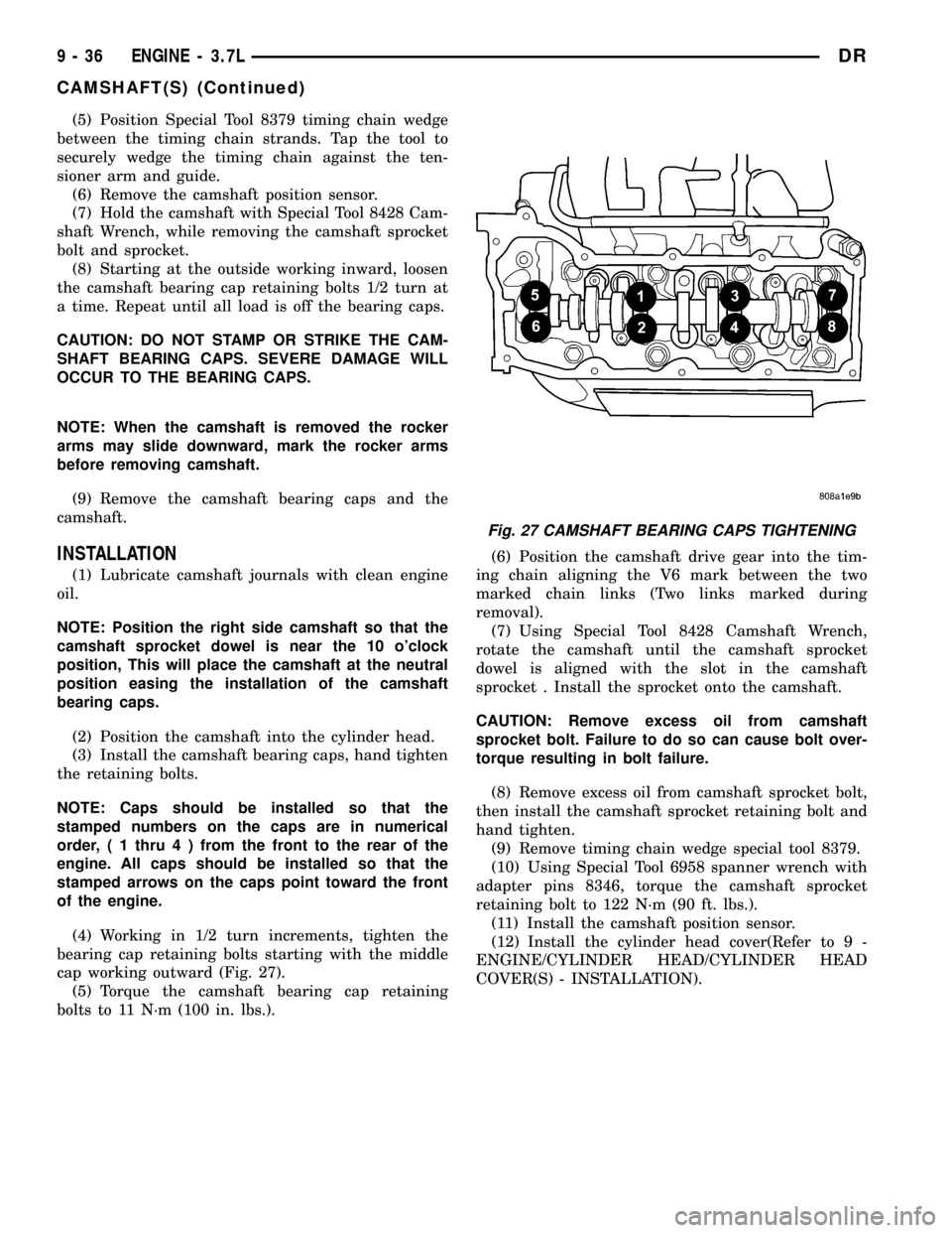
(4) Working in 1/2 turn increments, tighten the
bearing cap retaining bolts starting with the middle
cap working outward (Fig. 27).
(5) Torque the camshaft bearing cap retaining
bolts to 11 N´m (100 in. lbs.).(6) Position the camshaft drive gear into the tim-
ing chain aligning the V6 mark between the two
marked chain links (Two links marked during
removal).
(7) Using Special Tool 8428 Camshaft Wrench,
rotate the camshaft until the camshaft sprocket
dowel is aligned with the slot in the camshaft
sprocket . Install the sprocket onto the camshaft.
CAUTION: Remove excess oil from camshaft
sprocket bolt. Failure to do so can cause bolt over-
torque resulting in bolt failure.
(8) Remove excess oil from camshaft sprocket bolt,
then install the camshaft sprocket retaining bolt and
hand tighten.
(9) Remove timing chain wedge special tool 8379.
(10) Using Special Tool 6958 spanner wrench with
adapter pins 8346, torque the camshaft sprocket
retaining bolt to 122 N´m (90 ft. lbs.).
(11) Install the camshaft position sensor.
(12) Install the cylinder head cover(Refer to 9 -
ENGINE/CYLINDER HEAD/CYLINDER HEAD
COVER(S) - INSTALLATION).
Fig. 27 CAMSHAFT BEARING CAPS TIGHTENING
9 - 36 ENGINE - 3.7LDR
CAMSHAFT(S) (Continued)
Page 1260 of 2627
CYLINDER HEAD COVER(S)
REMOVAL
(1) Disconnect battery negative cable.
(2) Remove air cleaner assembly, resonator assem-
bly and air inlet hose.
(3) Drain cooling system, below the level of the
heater hoses(Refer to 7 - COOLING - STANDARD
PROCEDURE).
(4)
Remove accessory drive belt(Refer to 7 - COOL-
ING/ACCESSORY DRIVE/DRIVE BELTS - REMOVAL).
(5) Remove air conditioning compressor retaining
bolts and move compressor to the left.
(6) Remove heater hoses.
(7) Disconnect injector and ignition coil connectors.
(8) Disconnect and remove positive crankcase ven-
tilation (PCV) hose.
(9) Remove oil fill tube.
(10) Un-clip injector and ignition coil harness and
move away from cylinder head cover.
(11) Remove right rear breather tube and filter
assembly.
(12) Remove cylinder head cover retaining bolts.
(13) Remove cylinder head cover.
INSTALLATION
CAUTION: Do not use harsh cleaners to clean the
cylinder head covers. Severe damage to covers
may occur.
NOTE: The gasket may be used again, provided no
cuts, tears, or deformation has occurred.
(1) Clean cylinder head cover and both sealing sur-
faces. Inspect and replace gasket as necessary.
(2) Tighten cylinder head cover bolts and double
ended studs to 12 N´m (105 in. lbs).
(3) Install right rear breather tube and filter
assembly.
(4) Connect injector, ignition coil electrical connec-
tors and harness retaining clips.
(5) Install the oil fill tube.
(6) Install PCV hose.
(7) Install heater hoses.
(8) Install air conditioning compressor retaining
bolts.
(9) Install accessory drive belt(Refer to 7 - COOL-
ING/ACCESSORY DRIVE/DRIVE BELTS - INSTAL-
LATION).
(10) Fill Cooling system(Refer to 7 - COOLING -
STANDARD PROCEDURE).
(11) Install air cleaner assembly, resonator assem-
bly and air inlet hose.
(12) Connect battery negative cable.
ROCKER ARM
DESCRIPTION
The rocker arms are steel stampings with an inte-
gral roller bearing. The rocker arms incorporate a 2.8
mm (0.11 inch) oil hole in the lash adjuster socket for
roller and camshaft lubrication.
REMOVAL
NOTE: Disconnect the battery negative cable to pre-
vent accidental starter engagement.
(1) Remove the cylinder head cover (Refer to 9 -
ENGINE/CYLINDER HEAD/CYLINDER HEAD
COVER(S) - REMOVAL).
(2) For rocker arm removal on cylinder No. 4,
Rotate the crankshaft until cylinder No. 1 is at BDC
intake stroke.
(3) For rocker arm removal on cylinder No. 1,
Rotate the crankshaft until cylinder No. 1 is at BDC
combustion stroke.
(4) For rocker arm removal on cylinders No. 3 and
No. 5, Rotate the crankshaft until cylinder No. 1 is at
TDC exhaust stroke.
(5) For rocker arm removal on cylinders No. 2 and
No. 6, Rotate the crankshaft until cylinder No. 1 is at
TDC ignition stroke.
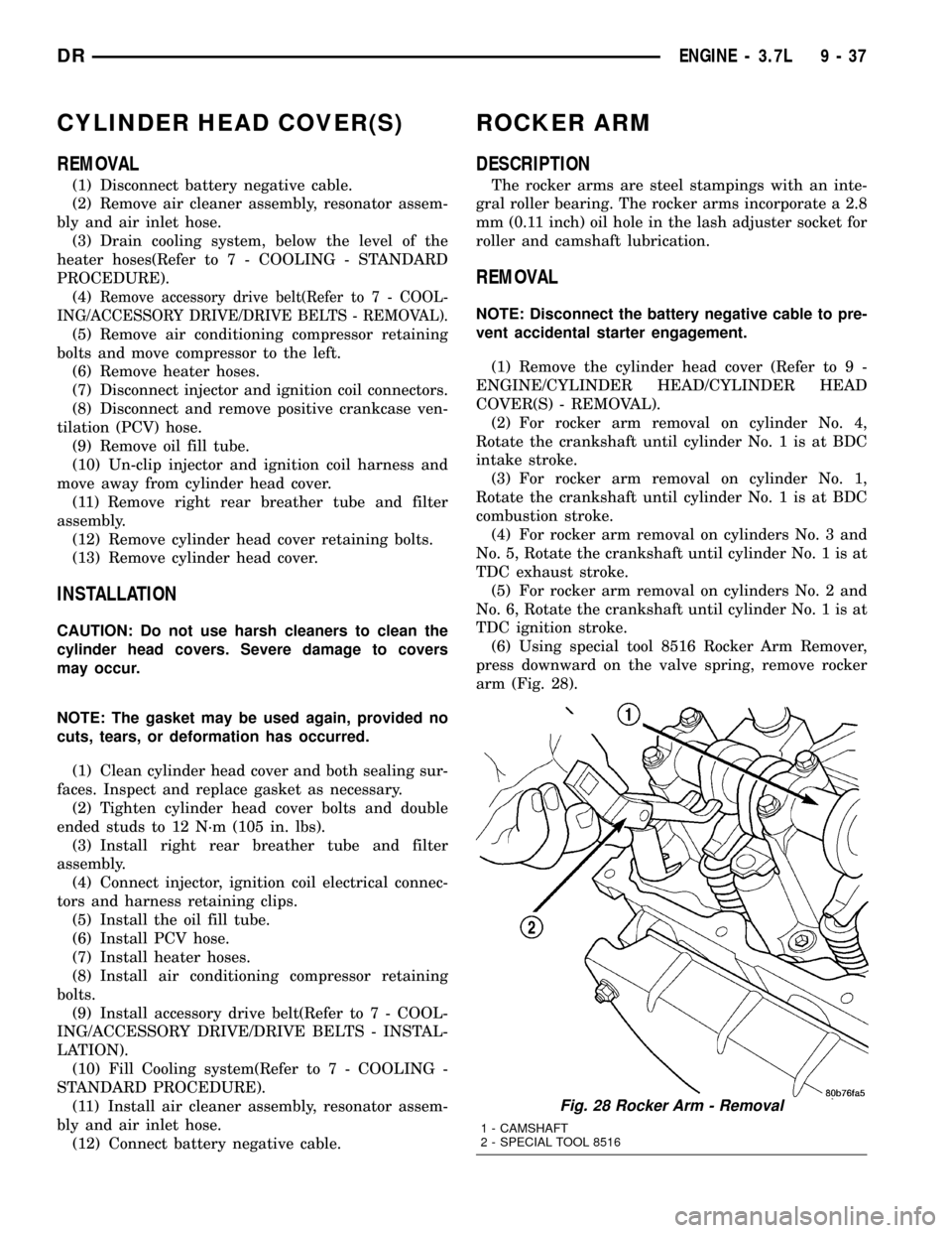
(6) Using special tool 8516 Rocker Arm Remover,
press downward on the valve spring, remove rocker
arm (Fig. 28).
Fig. 28 Rocker Arm - Removal
1 - CAMSHAFT
2 - SPECIAL TOOL 8516
DRENGINE - 3.7L 9 - 37
Page 1284 of 2627
REAR MOUNT
REMOVAL
(1) Raise the vehicle on a hoist.
(2) Using a suitable jack, support transmission.
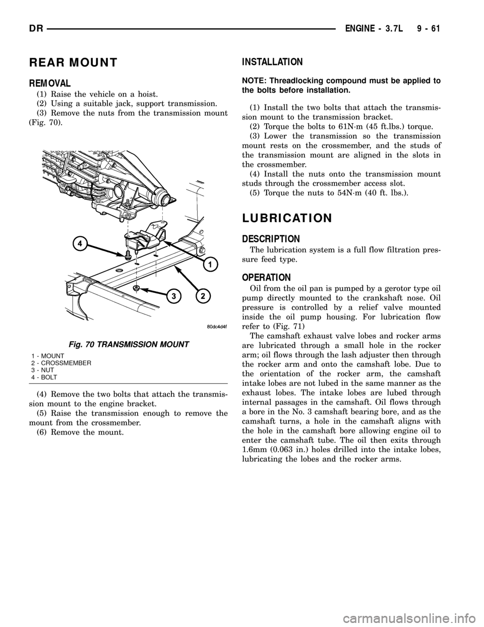
(3) Remove the nuts from the transmission mount
(Fig. 70).
(4) Remove the two bolts that attach the transmis-
sion mount to the engine bracket.
(5) Raise the transmission enough to remove the
mount from the crossmember.
(6) Remove the mount.
INSTALLATION
NOTE: Threadlocking compound must be applied to
the bolts before installation.
(1) Install the two bolts that attach the transmis-
sion mount to the transmission bracket.
(2) Torque the bolts to 61N´m (45 ft.lbs.) torque.
(3) Lower the transmission so the transmission
mount rests on the crossmember, and the studs of
the transmission mount are aligned in the slots in
the crossmember.
(4) Install the nuts onto the transmission mount
studs through the crossmember access slot.
(5) Torque the nuts to 54N´m (40 ft. lbs.).
LUBRICATION
DESCRIPTION
The lubrication system is a full flow filtration pres-
sure feed type.
OPERATION
Oil from the oil pan is pumped by a gerotor type oil
pump directly mounted to the crankshaft nose. Oil
pressure is controlled by a relief valve mounted
inside the oil pump housing. For lubrication flow
refer to (Fig. 71)
The camshaft exhaust valve lobes and rocker arms
are lubricated through a small hole in the rocker
arm; oil flows through the lash adjuster then through
the rocker arm and onto the camshaft lobe. Due to
the orientation of the rocker arm, the camshaft
intake lobes are not lubed in the same manner as the
exhaust lobes. The intake lobes are lubed through
internal passages in the camshaft. Oil flows through
a bore in the No. 3 camshaft bearing bore, and as the
camshaft turns, a hole in the camshaft aligns with
the hole in the camshaft bore allowing engine oil to
enter the camshaft tube. The oil then exits through
1.6mm (0.063 in.) holes drilled into the intake lobes,
lubricating the lobes and the rocker arms.
Fig. 70 TRANSMISSION MOUNT
1 - MOUNT
2 - CROSSMEMBER
3 - NUT
4 - BOLT
DRENGINE - 3.7L 9 - 61
Page 1288 of 2627
DIAGNOSIS AND TESTING - CHECKING
ENGINE OIL PRESSURE
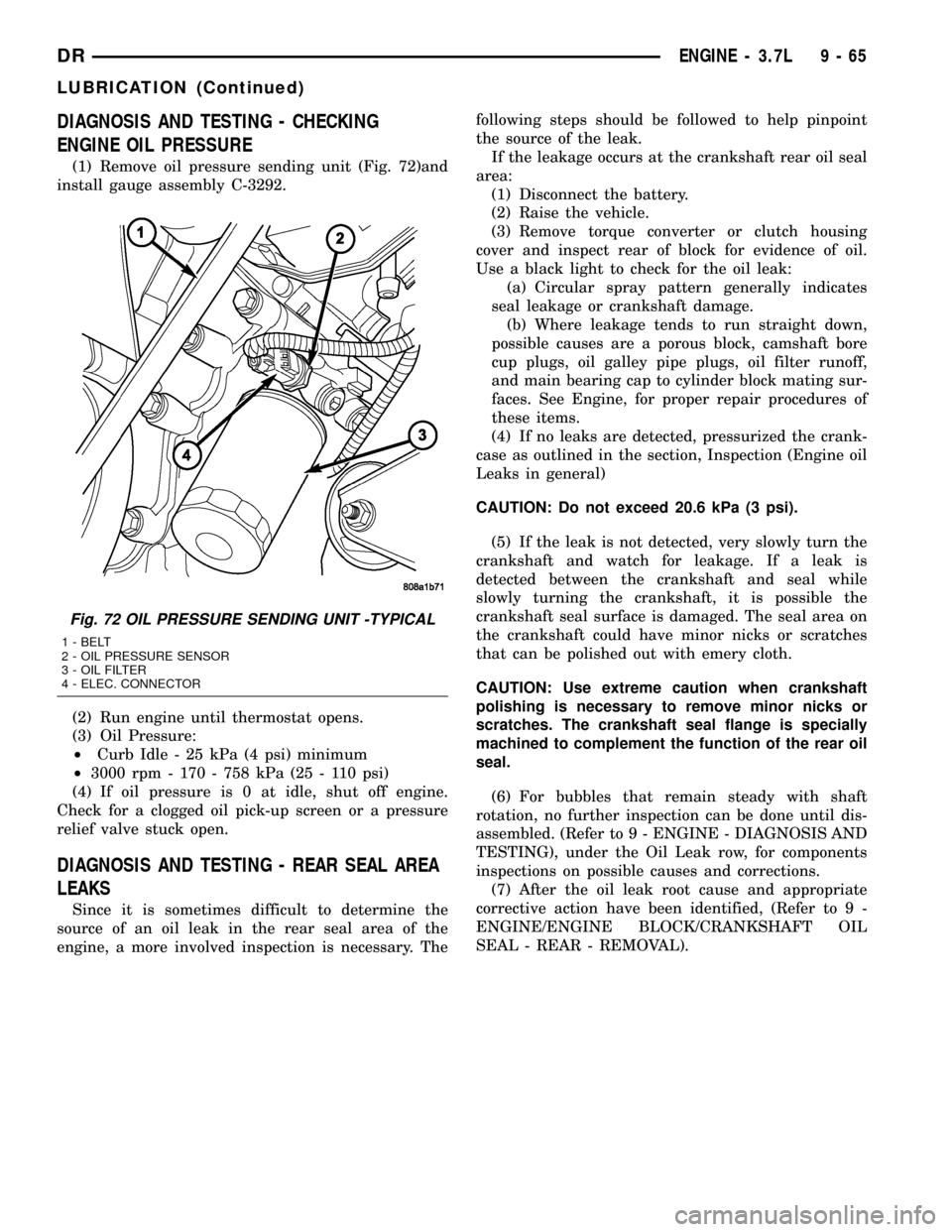
(1) Remove oil pressure sending unit (Fig. 72)and
install gauge assembly C-3292.
(2) Run engine until thermostat opens.
(3) Oil Pressure:
²Curb Idle - 25 kPa (4 psi) minimum
²3000 rpm - 170 - 758 kPa (25 - 110 psi)
(4) If oil pressure is 0 at idle, shut off engine.
Check for a clogged oil pick-up screen or a pressure
relief valve stuck open.
DIAGNOSIS AND TESTING - REAR SEAL AREA
LEAKS
Since it is sometimes difficult to determine the
source of an oil leak in the rear seal area of the
engine, a more involved inspection is necessary. Thefollowing steps should be followed to help pinpoint
the source of the leak.
If the leakage occurs at the crankshaft rear oil seal
area:
(1) Disconnect the battery.
(2) Raise the vehicle.
(3) Remove torque converter or clutch housing
cover and inspect rear of block for evidence of oil.
Use a black light to check for the oil leak:
(a) Circular spray pattern generally indicates
seal leakage or crankshaft damage.
(b) Where leakage tends to run straight down,
possible causes are a porous block, camshaft bore
cup plugs, oil galley pipe plugs, oil filter runoff,
and main bearing cap to cylinder block mating sur-
faces. See Engine, for proper repair procedures of
these items.
(4) If no leaks are detected, pressurized the crank-
case as outlined in the section, Inspection (Engine oil
Leaks in general)
CAUTION: Do not exceed 20.6 kPa (3 psi).
(5) If the leak is not detected, very slowly turn the
crankshaft and watch for leakage. If a leak is
detected between the crankshaft and seal while
slowly turning the crankshaft, it is possible the
crankshaft seal surface is damaged. The seal area on
the crankshaft could have minor nicks or scratches
that can be polished out with emery cloth.
CAUTION: Use extreme caution when crankshaft
polishing is necessary to remove minor nicks or
scratches. The crankshaft seal flange is specially
machined to complement the function of the rear oil
seal.
(6) For bubbles that remain steady with shaft
rotation, no further inspection can be done until dis-
assembled. (Refer to 9 - ENGINE - DIAGNOSIS AND
TESTING), under the Oil Leak row, for components
inspections on possible causes and corrections.
(7) After the oil leak root cause and appropriate
corrective action have been identified, (Refer to 9 -
ENGINE/ENGINE BLOCK/CRANKSHAFT OIL
SEAL - REAR - REMOVAL).
Fig. 72 OIL PRESSURE SENDING UNIT -TYPICAL
1 - BELT
2 - OIL PRESSURE SENSOR
3 - OIL FILTER
4 - ELEC. CONNECTOR
DRENGINE - 3.7L 9 - 65
LUBRICATION (Continued)
Page 1300 of 2627
block. A large washer on the idler shaft bolt and the
rear flange of the idler shaft are used to control
sprocket thrust movement. Pressurized oil is routed
through the center of the idler shaft to provide lubri-
cation for the two bushings used in the idler sprocket
assembly.
There are two secondary drive chains, both are
roller type, one to drive the camshaft in each SOHC
cylinder head. There are no shaft speed changes in
the secondary chain drive system. Each secondary
chain drives a 26 tooth cam sprocket directly from
the 26 tooth sprocket on the idler sprocket assembly.
A fixed chain guide and a hydraulic oil damped ten-
sioner are used to maintain tension in each second-
ary chain system. The hydraulic tensioners for the
secondary chain systems are fed pressurized oil from
oil reservoir pockets in the block. Each tensioner
incorporates a controlled leak path through a device
known as a vent disc located in the nose of the piston
to manage chain loads. Each tensioner also has a
mechanical ratchet system that limits chain slack if
the tensioner piston bleeds down after engine shut
down. The tensioner arms and guides also utilize
nylon wear faces for low friction and long wear. The
secondary timing chains receive lubrication from a
small orifice in the tensioners. This orifice is pro-
tected from clogging by a fine mesh screen which is
located on the back of the hydraulic tensioners.
STANDARD PROCEDURE
MEASURING TIMING CHAIN WEAR
NOTE: This procedure must be performed with the
timing chain cover removed.
(1) Remove the timing chain cover (Refer to 9 -
ENGINE/VALVE TIMING/TIMING BELT/CHAIN
AND SPROCKETS - REMOVAL).
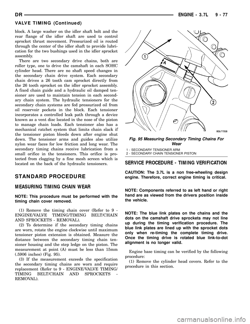
(2) To determine if the secondary timing chains
are worn, rotate the engine clockwise until maximum
tensioner piston extension is obtained. Measure the
distance between the secondary timing chain ten-
sioner housing and the step ledge on the piston. The
measurement at point (A) must be less than 15mm
(.5906 inches) (Fig. 95).
(3) If the measurement exceeds the specification
the secondary timing chains are worn and require
replacement (Refer to 9 - ENGINE/VALVE TIMING/
TIMING BELT/CHAIN AND SPROCKETS -
REMOVAL).
SERVICE PROCEDURE - TIMING VERIFICATION
CAUTION: The 3.7L is a non free-wheeling design
engine. Therefore, correct engine timing is critical.
NOTE: Components referred to as left hand or right
hand are as viewed from the drivers position inside
the vehicle.
NOTE: The blue link plates on the chains and the
dots on the camshaft drive sprockets may not line
up during the timing verification procedure. The
blue link plates are lined up with the sprocket dots
only when re-timing the complete timing drive.
Once the timing drive is rotated blue link-to-dot
alignment is no longer valid.
Engine base timing can be verified by the following
procedure:
(1) Remove the cylinder head covers. Refer to the
procedure in this section.
Fig. 95 Measuring Secondary Timing Chains For
Wear
1 - SECONDARY TENSIONER ARM
2 - SECONDARY CHAIN TENSIONER PISTON
DRENGINE - 3.7L 9 - 77
VALVE TIMING (Continued)