1998 DODGE RAM 1500 Camshaft position sensor
[x] Cancel search: Camshaft position sensorPage 832 of 2627

8W-30 FUEL/IGNITION SYSTEM
Component Page
A/C Compressor Clutch Relay............ 8W-30-9, 58
A/C Pressure Transducer......... 8W-30-23, 28, 29, 45
Accelerator Pedal Position Sensor . . . 8W-30-29, 47, 64, 65
Adjustable Pedal Motor................. 8W-30-61
Adjustable Pedal Relay.................. 8W-30-61
Adjustable Pedal Switch................. 8W-30-61
Ambient Temperature Sensor............. 8W-30-30
Auto Shut Down Relay................... 8W-30-4
Battery............................ 8W-30-52
Battery Temperature Sensor............ 8W-30-12, 56
Brake Lamp Switch............. 8W-30-8, 36, 57, 63
Camshaft Position Sensor........ 8W-30-10, 29, 45, 46
Capacitor........................... 8W-30-13
Clockspring..................... 8W-30-8, 36, 59
Coil On Plug No. 1.................. 8W-30-14, 39
Coil On Plug No. 2.................. 8W-30-15, 37
Coil On Plug No. 3.................. 8W-30-14, 39
Coil On Plug No. 4.................. 8W-30-15, 37
Coil On Plug No. 5.................. 8W-30-16, 39
Coil On Plug No. 6.................. 8W-30-13, 37
Coil On Plug No. 7.................. 8W-30-16, 39
Coil On Plug No. 8.................. 8W-30-13, 37
Condenser Fan Relay.................... 8W-30-9
Controller Antilock Brake............ 8W-30-6, 11, 57
Crankshaft Position Sensor............ 8W-30-10, 46
Data Link Connector............... 8W-30-9, 22, 55
Data Link Connector-Engine.............. 8W-30-51
EGR Solenoid................... 8W-30-28, 29, 32
Electronic Throttle Control Module.......... 8W-30-35
Engine Control Module....... 8W-30-42, 43, 44, 45, 46,
47, 48, 49, 50, 51, 52, 53, 54,
55, 56, 57, 58, 59, 60, 62, 63, 64, 65
Engine Coolant Temperature Sensor.... 8W-30-23, 41, 47
Engine Oil Pressure Switch.......... 8W-30-2, 53, 56
EVAP/Purge Solenoid................... 8W-30-12
Front Control Module................... 8W-30-61
Fuel Control Actuator................... 8W-30-50
Fuel Heater......................... 8W-30-60
Fuel Heater Relay..................... 8W-30-60
Fuel Injector No. 1.................. 8W-30-14, 40
Fuel Injector No. 2.................. 8W-30-15, 38
Fuel Injector No. 3.................. 8W-30-14, 40
Fuel Injector No. 4.................. 8W-30-15, 38
Fuel Injector No. 5.................. 8W-30-14, 40
Fuel Injector No. 6.................. 8W-30-15, 38
Fuel Injector No. 7.................. 8W-30-16, 40
Fuel Injector No. 8.................. 8W-30-13, 38
Fuel Injector Pack No. 1................. 8W-30-42
Fuel Injector Pack No. 2............ 8W-30-42, 43, 44
Fuel Injector Pack No. 3................. 8W-30-44
Fuel Pump Module................... 8W-30-3, 58
Fuel Pump Motor...................... 8W-30-48
Fuel Pump Relay....................... 8W-30-3
Fuse 2.............................. 8W-30-4
Fuse 5........................... 8W-30-25, 62
Fuse 12............................ 8W-30-60
Fuse 17............................. 8W-30-3
Fuse 19............................ 8W-30-52
Fuse 23............................. 8W-30-2Component Page
Fuse 36.......................... 8W-30-54, 61
Fuse 40............................ 8W-30-61
Fuse 49............................. 8W-30-4
Fuse 50..................... 8W-30-2, 55, 58, 62
Fusible Link......................... 8W-30-52
G104........................ 8W-30-3, 8, 25, 60
G105............................ 8W-30-56, 58
G107........... 8W-30-2, 7, 15, 18, 19, 20, 21, 30, 32
G114 .............................. 8W-30-53
G120............................ 8W-30-51, 60
G201............................... 8W-30-6
G202.............................. 8W-30-61
Generator......................... 8W-30-7, 51
Idle Air Control Motor................... 8W-30-9
Ignition Switch..................... 8W-30-6, 22
Inlet Air Temperature Sensor............. 8W-30-49
Input Speed Sensor.................... 8W-30-24
Instrument Cluster.................... 8W-30-30
Intake Air Heater Relay No. 1............. 8W-30-56
Intake Air Heater Relay No. 2............. 8W-30-56
Intake Air Temperature Sensor.......... 8W-30-23, 41
Intake Air Temperature/Manifold Absolute
Pressure Sensor..................... 8W-30-50
Integrated Power Module.... 8W-30-2, 3, 4, 9, 25, 52, 54,
55, 58, 60, 61, 62, 64
Knock Sensor........................ 8W-30-31
Knock Sensor-Left..................... 8W-30-33
Knock Sensor-Right.................... 8W-30-33
Lift Pump Motor...................... 8W-30-51
Line Pressure Sensor................... 8W-30-17
Manifold Absolute Pressure Sensor..... 8W-30-23, 29, 41
Natural Vacuum Leak Detection Assembly..... 8W-30-7
Output Speed Sensor................. 8W-30-24, 62
Oxygen Sensor 1/1 Upstream........... 8W-30-20, 21
Oxygen Sensor 1/2 Downstream......... 8W-30-18, 19
Oxygen Sensor 2/1 Upstream........... 8W-30-20, 21
Oxygen Sensor 2/2 Downstream......... 8W-30-18, 19
Oxygen Sensor Downstream Relay........... 8W-30-4
Power Steering Pressure Switch............ 8W-30-7
Powertrain Control Module....... 8W-30-2, 3, 4, 5, 6, 7,
8, 9, 10, 11, 12, 13, 14, 15, 16,
17, 18, 19, 20, 21, 22, 23, 24,
25, 26, 27, 28, 29, 30, 31, 32,
33, 35, 36, 37, 38, 39, 40, 41
PTCNo.1 ....................... 8W-30-3, 9, 58
Pto Switch........................... 8W-30-6
Speed Control Servo.................. 8W-30-8, 63
Speed Control Switch-Left............. 8W-30-36, 59
Speed Control Switch-Right............ 8W-30-36, 59
Starter Motor Relay.................. 8W-30-2, 64
Throttle Position Sensor................. 8W-30-17
Tow/Haul Overdrive Switch............. 8W-30-6, 64
Transmission Control Relay............ 8W-30-25, 62
Transmission Range Sensor............... 8W-30-64
Transmission Solenoid Assembly......... 8W-30-54, 62
Transmission Solenoid/TRS Assembly . 8W-30-5, 25, 26, 27
Vacuum Pump........................ 8W-30-58
Vistronic Fan Drive.................... 8W-30-54
Water In Fuel Sensor................ 8W-30-47, 48
DR8W-30 FUEL/IGNITION SYSTEM 8W - 30 - 1
Page 898 of 2627

8W-31 TRANSMISSION CONTROL SYSTEM
Component Page
Automatic Day/Night Mirror........... 8W-31-7
Brake Lamp Switch.................. 8W-31-9
Camshaft Position Sensor.............. 8W-31-6
Clockspring........................ 8W-31-10
Clutch Interlock Brake Switch......... 8W-31-11
Data Link Connector................ 8W-31-16
Engine Control Module......... 8W-31-7, 8, 9, 10
Front Control Module................. 8W-31-2
Fuse 5.......................... 8W-31-2, 8
Fuse 38.......................... 8W-31-2, 7
Fuse 43........................... 8W-31-11
Fuse 50............................ 8W-31-8
G104..................... 8W-31-2, 11, 14, 16
G107............................. 8W-31-14
G201........................... 8W-31-3, 10
Input Speed Sensor.................. 8W-31-5
Instrument Cluster................ 8W-31-7, 14
Integrated Power Module....... 8W-31-2, 7, 8, 11Component Page
Line Pressure Sensor................. 8W-31-6
Output Speed Sensor............... 8W-31-5, 8
Powertrain Control Module..... 8W-31-2, 3, 4, 5, 6
Speed Control Servo.................. 8W-31-9
Speed Control Switch-Left............ 8W-31-10
Speed Control Switch-Right........... 8W-31-10
Starter Motor Relay................. 8W-31-11
Tow/Haul Overdrive Switch......... 8W-31-3, 10
Transfer Case Control
Module.............. 8W-31-11, 12, 13, 14, 16
Transfer Case Mode Sensor........ 8W-31-12, 13
Transfer Case Selector Switch......... 8W-31-14
Transfer Case Shift Motor............ 8W-31-16
Transmission Control Relay.......... 8W-31-2, 8
Transmission Range Sensor............ 8W-31-7
Transmission Solenoid Assembly........ 8W-31-8
Transmission Solenoid/TRS Assembly . 8W-31-2, 3, 4
DR8W-31 TRANSMISSION CONTROL SYSTEM 8W - 31 - 1
Page 1051 of 2627

Component Page
C315............................. 8W-80-39
C316 (Heated Seats)................. 8W-80-39
C316............................. 8W-80-40
C319............................. 8W-80-40
C319............................. 8W-80-40
C320............................. 8W-80-40
C320............................. 8W-80-41
C322 (Except Heated Seats)........... 8W-80-41
C322............................. 8W-80-41
C323 (Except Heated Seats)........... 8W-80-42
C323 (Except Heated Seats)........... 8W-80-42
C323 (Heated Seats)................. 8W-80-42
C323 (Heated Seats)................. 8W-80-43
C327 (Dual Rear Wheels)............. 8W-80-43
C327 (Dual Rear Wheels)............. 8W-80-43
C328 (Dual Rear Wheels)............. 8W-80-43
C328 (Dual Rear Wheels)............. 8W-80-44
Camshaft Position Sensor (NGC)....... 8W-80-44
Camshaft Position Sensor (Diesel)...... 8W-80-44
Capacitor (3.7L/4.7L)................ 8W-80-44
Center High Mounted Stop Lamp/cargo
Lamp.......................... 8W-80-45
Cigar Lighter Outlet................. 8W-80-45
Clearance Lamp No. 1 (Heavy Duty).... 8W-80-45
Clearance Lamp No. 2 (Heavy Duty).... 8W-80-45
Clearance Lamp No. 3 (Heavy Duty).... 8W-80-46
Clearance Lamp No. 4 (Heavy Duty).... 8W-80-46
Clearance Lamp No. 5 (Heavy Duty).... 8W-80-46
Clockspring C1..................... 8W-80-46
Clockspring C2..................... 8W-80-47
Clockspring C3..................... 8W-80-47
Clockspring C4..................... 8W-80-47
Clutch Interlock Brake Switch......... 8W-80-47
Coil On Plug No. 1 (3.7L/4.7L)......... 8W-80-47
Coil On Plug No. 1 (5.7L)............. 8W-80-48
Coil On Plug No. 2 (3.7L/4.7L)......... 8W-80-48
Coil On Plug No. 2 (5.7L)............. 8W-80-48
Coil On Plug No. 3 (3.7L/4.7L)......... 8W-80-48
Coil On Plug No. 3 (5.7L)............. 8W-80-49
Coil On Plug No. 4 (3.7L/4.7L)......... 8W-80-49
Coil On Plug No. 4 (5.7L)............. 8W-80-49
Coil On Plug No. 5 (3.7L/4.7L)......... 8W-80-49
Coil On Plug No. 5 (5.7L)............. 8W-80-50
Coil On Plug No. 6 (3.7L/4.7L)......... 8W-80-50
Coil On Plug No. 6 (5.7L)............. 8W-80-50
Coil On Plug No. 7 (4.7L)............. 8W-80-50
Coil On Plug No. 7 (5.7L)............. 8W-80-51
Coil On Plug No. 8 (4.7L)............. 8W-80-51
Coil On Plug No. 8 (5.7L)............. 8W-80-51
Compass/Mini-Trip Computer (Except
Base).......................... 8W-80-51
Condenser Fan (NGC)............... 8W-80-52
Controller Anitlock Brake C1.......... 8W-80-52
Controller Antilock Brake C2 (ABS)..... 8W-80-52Component Page
Crankshaft Position Sensor (3.7L)...... 8W-80-52
Crankshaft Position Sensor (4.7L)...... 8W-80-53
Crankshaft Position Sensor (5.7L)...... 8W-80-53
Crankshaft Position Sensor (Diesel)..... 8W-80-53
Cylinder Lock Switch-Driver (Premium) . . 8W-80-53
Data Link Connector................ 8W-80-53
Data Link Connector-Engine (Diesel).... 8W-80-54
Dome Lamp....................... 8W-80-54
Door Ajar Switch-Driver.............. 8W-80-54
Door Ajar Switch-Left Rear........... 8W-80-54
Door Ajar Switch-Passenger........... 8W-80-55
Door Ajar Switch-Right Rear.......... 8W-80-55
Door Lock Motor/Ajar Switch-Driver.... 8W-80-55
Door Lock Motor/Ajar Switch-Left Rear . . 8W-80-55
Door Lock Motor/Ajar Switch-Passenger . 8W-80-56
Door Lock Motor/Ajar Switch-Right Rear . 8W-80-56
Door Lock Switch-Passenger........... 8W-80-56
Driver Blend Door Actuator (Dual Zone) . 8W-80-56
Driver Door Module C1.............. 8W-80-57
Driver Door Module C2.............. 8W-80-57
EGR Solenoid (4.7L/5.7L)............. 8W-80-57
Electric Brake Provision.............. 8W-80-58
Electric Throttle Control Module....... 8W-80-58
Engine Control Module C1 (Diesel)..... 8W-80-58
Engine Control Module C2 (Diesel)..... 8W-80-60
Engine Coolant Temperature Sensor
(Diesel)......................... 8W-80-61
Engine Coolant Temperature Sensor
(Gas)........................... 8W-80-61
Engine Oil Pressure Switch........... 8W-80-61
EVAP/Purge Solenoid (NGC).......... 8W-80-61
Evaporator Temperature Sensor........ 8W-80-62
Fender Lamp-Front Left (Dual Rear
Wheels)......................... 8W-80-62
Fender Lamp-Front Right (Dual Rear
Wheels)......................... 8W-80-62
Fender Lamp-Rear Left (Dual Rear
Wheels)......................... 8W-80-62
Fender Lamp-Rear Right (Dual Rear
Wheels)......................... 8W-80-62
Fog Lamp-Left..................... 8W-80-63
Fog Lamp-Right.................... 8W-80-63
Fuel Control Actuator (Diesel)......... 8W-80-63
Fuel Heater (Diesel)................. 8W-80-63
Fuel Injector No. 1 (Gas)............. 8W-80-63
Fuel Injector No. 2 (Gas)............. 8W-80-64
Fuel Injector No. 3 (Gas)............. 8W-80-64
Fuel Injector No. 4 (Gas)............. 8W-80-64
Fuel Injector No. 5 (Gas)............. 8W-80-64
Fuel Injector No. 6 (Gas)............. 8W-80-65
Fuel Injector No. 7 (Gas)............. 8W-80-65
Fuel Injector No. 8 (Gas)............. 8W-80-65
Fuel Injector Pack No. 1 (Diesel)....... 8W-80-65
Fuel Injector Pack No. 2 (Diesel)....... 8W-80-66
Fuel Injector Pack No. 3 (Diesel)....... 8W-80-66
8W - 80 - 2 8W-80 CONNECTOR PIN-OUTSDR
Page 1093 of 2627

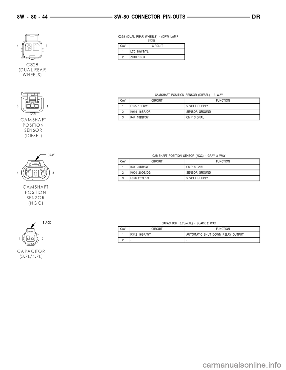
C328 (DUAL REAR WHEELS) - (DRW LAMP
SIDE)
CAV CIRCUIT
1 L70 18WT/YL
2 Z948 18BK
CAMSHAFT POSITION SENSOR (DIESEL)-3WAY
CAV CIRCUIT FUNCTION
1 F855 18PK/YL 5 VOLT SUPPLY
2 K916 18BR/OR SENSOR GROUND
3 K44 18DB/GY CMP SIGNAL
CAMSHAFT POSITION SENSOR (NGC) - GRAY 3 WAY
CAV CIRCUIT FUNCTION
1 K44 20DB/GY CMP SIGNAL
2 K900 20DB/DG SENSOR GROUND
3 F856 20YL/PK 5 VOLT SUPPLY
CAPACITOR (3.7L/4.7L) - BLACK 2 WAY
CAV CIRCUIT FUNCTION
1 K342 16BR/WT AUTOMATIC SHUT DOWN RELAY OUTPUT
2- -
8W - 80 - 44 8W-80 CONNECTOR PIN-OUTSDR
Page 1156 of 2627

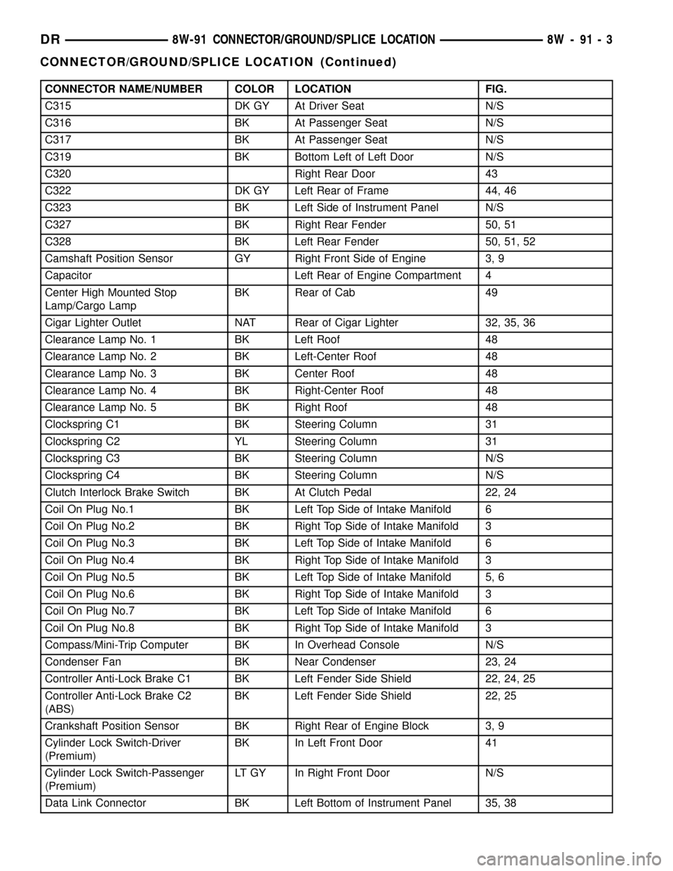
CONNECTOR NAME/NUMBER COLOR LOCATION FIG.
C315 DK GY At Driver Seat N/S
C316 BK At Passenger Seat N/S
C317 BK At Passenger Seat N/S
C319 BK Bottom Left of Left Door N/S
C320 Right Rear Door 43
C322 DK GY Left Rear of Frame 44, 46
C323 BK Left Side of Instrument Panel N/S
C327 BK Right Rear Fender 50, 51
C328 BK Left Rear Fender 50, 51, 52
Camshaft Position Sensor GY Right Front Side of Engine 3, 9
Capacitor Left Rear of Engine Compartment 4
Center High Mounted Stop
Lamp/Cargo LampBK Rear of Cab 49
Cigar Lighter Outlet NAT Rear of Cigar Lighter 32, 35, 36
Clearance Lamp No. 1 BK Left Roof 48
Clearance Lamp No. 2 BK Left-Center Roof 48
Clearance Lamp No. 3 BK Center Roof 48
Clearance Lamp No. 4 BK Right-Center Roof 48
Clearance Lamp No. 5 BK Right Roof 48
Clockspring C1 BK Steering Column 31
Clockspring C2 YL Steering Column 31
Clockspring C3 BK Steering Column N/S
Clockspring C4 BK Steering Column N/S
Clutch Interlock Brake Switch BK At Clutch Pedal 22, 24
Coil On Plug No.1 BK Left Top Side of Intake Manifold 6
Coil On Plug No.2 BK Right Top Side of Intake Manifold 3
Coil On Plug No.3 BK Left Top Side of Intake Manifold 6
Coil On Plug No.4 BK Right Top Side of Intake Manifold 3
Coil On Plug No.5 BK Left Top Side of Intake Manifold 5, 6
Coil On Plug No.6 BK Right Top Side of Intake Manifold 3
Coil On Plug No.7 BK Left Top Side of Intake Manifold 6
Coil On Plug No.8 BK Right Top Side of Intake Manifold 3
Compass/Mini-Trip Computer BK In Overhead Console N/S
Condenser Fan BK Near Condenser 23, 24
Controller Anti-Lock Brake C1 BK Left Fender Side Shield 22, 24, 25
Controller Anti-Lock Brake C2
(ABS)BK Left Fender Side Shield 22, 25
Crankshaft Position Sensor BK Right Rear of Engine Block 3, 9
Cylinder Lock Switch-Driver
(Premium)BK In Left Front Door 41
Cylinder Lock Switch-Passenger
(Premium)LT GY In Right Front Door N/S
Data Link Connector BK Left Bottom of Instrument Panel 35, 38
DR8W-91 CONNECTOR/GROUND/SPLICE LOCATION 8W - 91 - 3
CONNECTOR/GROUND/SPLICE LOCATION (Continued)
Page 1163 of 2627

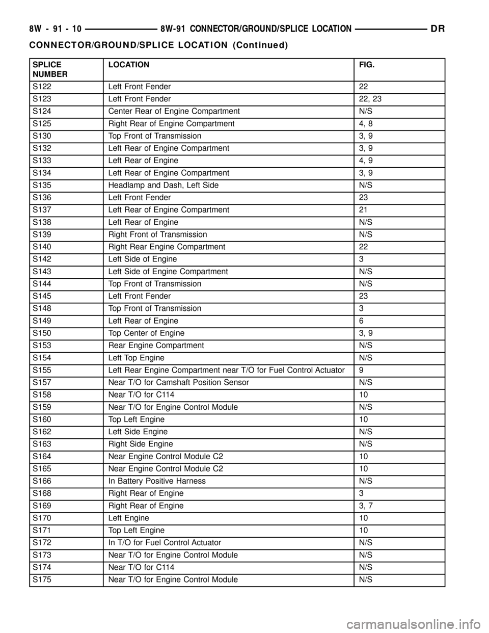
SPLICE
NUMBERLOCATION FIG.
S122 Left Front Fender 22
S123 Left Front Fender 22, 23
S124 Center Rear of Engine Compartment N/S
S125 Right Rear of Engine Compartment 4, 8
S130 Top Front of Transmission 3, 9
S132 Left Rear of Engine Compartment 3, 9
S133 Left Rear of Engine 4, 9
S134 Left Rear of Engine Compartment 3, 9
S135 Headlamp and Dash, Left Side N/S
S136 Left Front Fender 23
S137 Left Rear of Engine Compartment 21
S138 Left Rear of Engine N/S
S139 Right Front of Transmission N/S
S140 Right Rear Engine Compartment 22
S142 Left Side of Engine 3
S143 Left Side of Engine Compartment N/S
S144 Top Front of Transmission N/S
S145 Left Front Fender 23
S148 Top Front of Transmission 3
S149 Left Rear of Engine 6
S150 Top Center of Engine 3, 9
S153 Rear Engine Compartment N/S
S154 Left Top Engine N/S
S155 Left Rear Engine Compartment near T/O for Fuel Control Actuator 9
S157 Near T/O for Camshaft Position Sensor N/S
S158 Near T/O for C114 10
S159 Near T/O for Engine Control Module N/S
S160 Top Left Engine 10
S162 Left Side Engine N/S
S163 Right Side Engine N/S
S164 Near Engine Control Module C2 10
S165 Near Engine Control Module C2 10
S166 In Battery Positive Harness N/S
S168 Right Rear of Engine 3
S169 Right Rear of Engine 3, 7
S170 Left Engine 10
S171 Top Left Engine 10
S172 In T/O for Fuel Control Actuator N/S
S173 Near T/O for Engine Control Module N/S
S174 Near T/O for C114 N/S
S175 Near T/O for Engine Control Module N/S
8W - 91 - 10 8W-91 CONNECTOR/GROUND/SPLICE LOCATIONDR
CONNECTOR/GROUND/SPLICE LOCATION (Continued)
Page 1234 of 2627

(12) Disconnect heater hoses from heater core and
remove hose assembly.
(13) Disconnect throttle and speed control cables.
(14) Remove upper radiator hose from engine.
(15) Remove lower radiator hose from engine.
(16) Remove radiator/cooling module assembly.
(17) Disconnect the engine to body ground straps
at the left side of cowl.
(18) Disconnect the engine wiring harness at the
following points:
²Intake air temperature (IAT) sensor
²Fuel Injectors
²Throttle Position (TPS) Switch
²Idle Air Control (IAC) Motor
²Engine Oil Pressure Switch
²Engine Coolant Temperature (ECT) Sensor
²Manifold Absolute Pressure MAP) Sensor
²Camshaft Position (CMP) Sensor
²Coil Over Plugs
²Crankshaft Position Sensor
(19) Remove coil over plugs.
(20) Release fuel rail pressure.
(21) Remove fuel rail and secure away from
engine.
NOTE: It is not necessary to release the quick con-
nect fitting from the fuel supply line for engine
removal.
(22) Remove the PCV hose.
(23) Remove the breather hoses.
(24) Remove the vacuum hose for the power brake
booster.
(25) Disconnect knock sensors.
(26) Remove engine oil dipstick tube.
(27) Remove intake manifold.
(28) Install engine lifting fixture,special tool#8247,
using original fasteners from the removed intake
manifold, and fuel rail. Torque to factory specifica-
tions.
NOTE: Recheck bolt torque for engine lift plate
before removing engine.
(29) Secure the left and right engine wiring har-
nesses away from engine.
(30) Raise vehicle.
(31) Disconnect oxygen sensor wiring.
(32) Disconnect crankshaft postion sensor.
(33) Disconnect the engine block heater power
cable, if equipped.
(34) Disconnect the front propshaft at the front
differential and secure out of way.
NOTE: It is necessary to disconnect the front prop-
shaft for access to the starter and left side exhaust
flange.(35) Remove the starter.
(36) Remove the ground straps from the left and
right side of the block.
(37) Disconnect the right and left exhaust pipes at
the manifolds and from the crossover, and remove
from the vehicle.
NOTE: The exhaust clamps at the manifolds cannot
be reused. New clamps must be used or leaks may
occur.
(38) Remove the structural cover.
(39) Remove torque convertor bolts, and mark
location for reassembly.
(40) Remove transmission bellhousing to engine
bolts.
(41) Remove left and right engine mount thru
bolts.
(42) Lower the vehicle.
(43) Support the transmission with a suitable jack.
(44) Connect a suitable engine hoist to the engine
lift plate.
(45) Remove engine from vehicle.
INSTALLATION
(1) Position the engine in the vehicle.
(2) Install both left and right side engine mounts
onto engine.
(3) Raise the vehicle.
(4) Install the transmission bellhousing to engine
mounting bolts. Tighten the bolts to 41 N´m (30ft.
lbs.).
(5) Tighten the engine mount thru bolts.
(6) Install the torque convertor bolts.
(7) Connect the ground straps on the left and right
side of the engine.
(8) Install the starter.
(9) Connect the crankshaft position sensor.
(10) Install the engine block heater power cable, if
equipped.
CAUTION: The structural cover requires a specific
torque sequence. Failure to follow this sequence
may cause severe damage to the cover.
(11) Install the structural cover.
NOTE: New clamps must be used on exhaust man-
ifold flanges. Failure to use new clamps may result
in exhaust leaks.
(12) Install the left and right exhaust pipes.
(13) Connect the left and right oxygen sensors.
(14) Lower vehicle.
(15) Remove the engine lift plate.
(16) Connect the knock sensors.
DRENGINE - 3.7L 9 - 11
ENGINE - 3.7L (Continued)
Page 1235 of 2627

(17) Connect the engine to body ground straps at
the left side of the cowl.
(18) Install the intake manifold.
(19) Install the engine oil dipstick tube.
(20) Install the power brake booster vacuum hose.
(21) Install the breather hoses.
(22) Install the PCV hose.
(23) Install the fuel rail.
(24) Install the coil over plugs.
(25) Connect the engine wiring harness at the fol-
lowing points:
²Intake air temperature (IAT) sensor
²Fuel Injectors
²Throttle Position (TPS) Switch
²Idle Air Control (IAC) Motor
²Engine Oil Pressure Switch
²Engine Coolant Temperature (ECT) Sensor
²Manifold Absolute Pressure MAP) Sensor
²Camshaft Position (CMP) Sensor
²Coil Over Plugs
²Crankshaft Position Sensor
(26) Reinstall the radiator/cooling module assem-
bly.
(27) Connect lower radiator hose.
(28) Connect upper radiator hose.
(29) Connect throttle and speed control cables.
(30) Install the heater hose assembly.
(31) Install coolant recovery bottle.
(32) Install the power steering pump.
(33) Install the generator.
(34) Install the A/C compressor.
(35) Install the drive belt.
(36) Install the fan shroud with the viscous fan
assembly.
(37) Install the radiator core support bracket.
(38) Install the air cleaner assembly.
(39) Refill the engine cooling system.
(40) Recharge the air conditioning.
(41) Install the hood.
(42) Check and fill engine oil.
(43) Connect the battery negative cable.
(44) Start the engine and check for leaks.SPECIFICATIONS
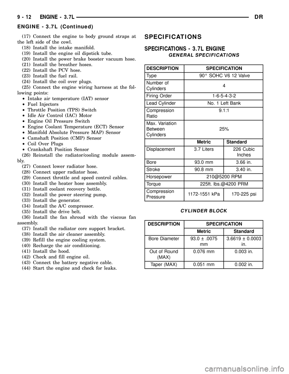
SPECIFICATIONS - 3.7L ENGINE
GENERAL SPECIFICATIONS
DESCRIPTION SPECIFICATION
Type 90É SOHC V6 12 Valve
Number of
Cylinders4
Firing Order 1-6-5-4-3-2
Lead Cylinder No. 1 Left Bank
Compression
Ratio9.1:1
Max. Variation
Between
Cylinders25%
Metric Standard
Displacement 3.7 Liters 226 Cubic
Inches
Bore 93.0 mm 3.66 in.
Stroke 90.8 mm 3.40 in.
Horsepower 210@5200 RPM
Torque 225ft. lbs.@4200 PRM
Compression
Pressure1172-1551 kPa 170-225 psi
CYLINDER BLOCK
DESCRIPTION SPECIFICATION
Metric Standard
Bore Diameter 93.0 .0075
mm3.6619 0.0003
in.
Out of Round
(MAX)0.076 mm 0.003 in.
Taper (MAX) 0.051 mm 0.002 in.
9 - 12 ENGINE - 3.7LDR
ENGINE - 3.7L (Continued)