1998 DODGE RAM 1500 Sway bar
[x] Cancel search: Sway barPage 60 of 2627

ends of the bar mount to the lower suspension arm.
All mounting points of the stabilizer bar are isolated
by bushings (Fig. 28).
OPERATION
The stabilizer bar is used to minimize vehicle front
sway during turns. The bar helps to maintain a flat
attitude to the road surface.
REMOVAL
NOTE: To service the stabilizer bar the vehicle
should be on a drive on hoist. The vehicle suspen-
sion must be at curb height for stabilizer bar instal-
lation.
(1) Remove the stabilizer bar link upper nuts and
remove the retainers and grommets (Fig. 29).
(2) Remove the stabilizer bar retainer, bolts and
retainers from the frame crossmember (Fig. 29) and
remove the bar.
(3) If necessary, remove the bushings from the sta-
bilizer barDo not cut the old bushings off the
stabilizer bar use a mixture of soapy water in
order to aid in sliding the bushing off.
INSTALLATION
NOTE: To service the stabilizer bar the vehicle must
be on a drive on hoist. The vehicle suspension
must be at curb height for stabilizer bar installation.
(1) If removed, Install the bushings on the stabi-
lizer bar using a mixture of soapy water or equiva-
lent in order to slide the bushing over the bar with
easeDo not cut the new bushing for installa-
tion.
(2) Position the stabilizer bar on the frame cross-
member brackets and install the bracket and bolts
finger-tight (Fig. 29).NOTE: Check the alignment of the bar to ensure
there is no interference with the either frame rail or
chassis component. Spacing should be equal on
both sides.
(3) Install the stabilizer bar to the stabilizer link
and install the grommets and retainers.
(4) Install the nuts to the stabilizer link and
tighten to 38 N´m (27 ft. lbs.).
(5) Tighten the brackets to the frame to 61 N´m
(45 ft. lbs.).
STABILIZER LINK
REMOVAL
REMOVAL - 4X4
(1) Raise and support the vehicle.
(2) Remove the lower nut (Fig. 29).
(3) Remove the upper nut, retainers and grommets
(Fig. 29).
(4) Remove the stabilizer link from the vehicle
(Fig. 29).
REMOVAL - 4X2
(1) Raise and support the vehicle.
(2) Remove the lower nut (Fig. 29).
(3) Remove the upper nut, retainer and grommets
(Fig. 29).
(4) Remove the stabilizer link from the vehicle
(Fig. 29).
Fig. 28 STABILIZER BAR
Fig. 29 STABILIZER LINK
1 - STABILIZER LINK
2 - SWAY BAR BRACKET
DRFRONT - INDEPENDENT FRONT SUSPENSION 2 - 25
STABILIZER BAR (Continued)
Page 1550 of 2627

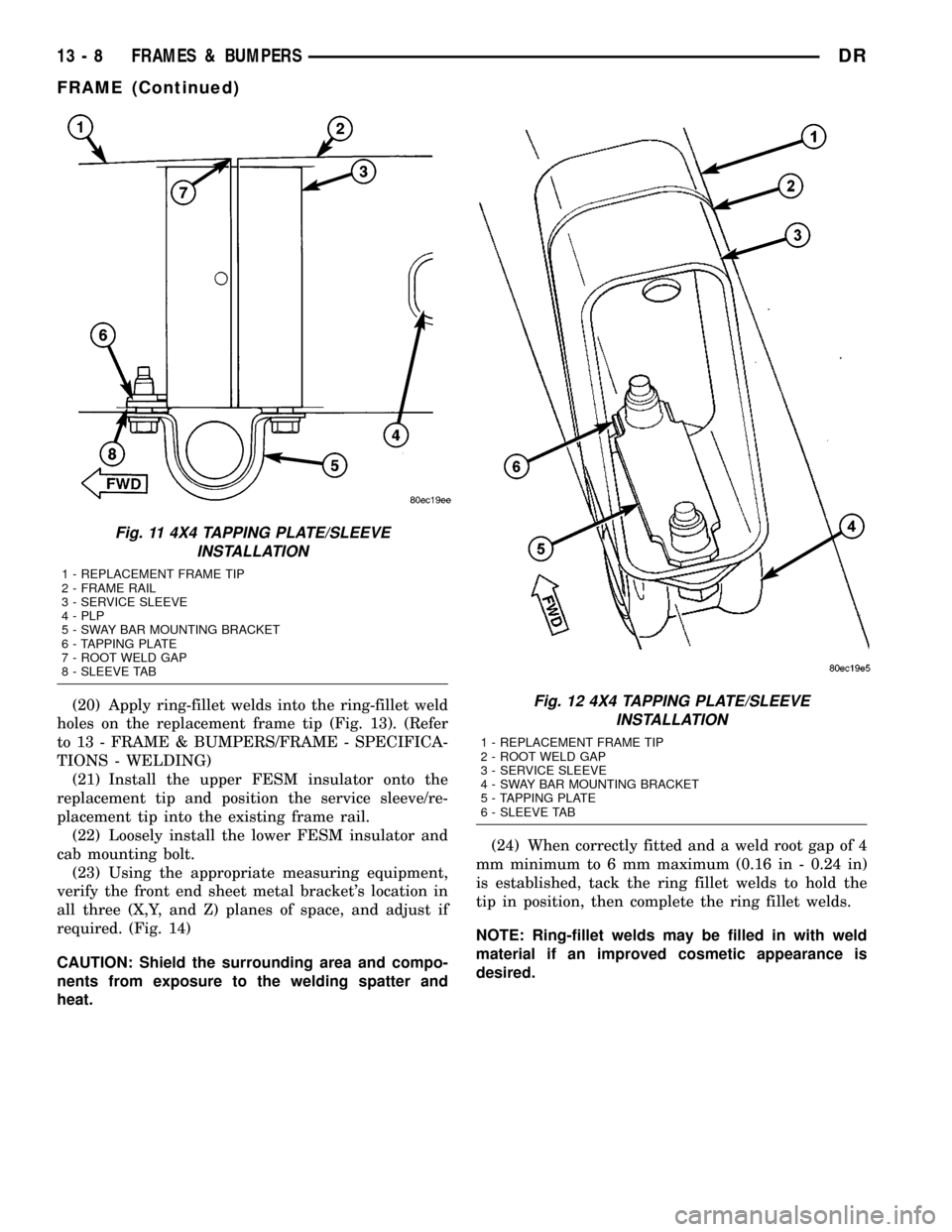
(17) On 4X4 models use the service sleeve as a
template to drill a hole in the frame tip to accommo-
date the sway bar mounting bolt. (Fig. 11)
(18) Slide the service sleeve into the replacement
frame tip and align to the 2 mm (0.08 in.) off center
line made previously during the sleeve assembly and
tack the ring fillet welds to hold them in place. (Fig.
9) (Fig. 10) (Fig. 11) (Fig. 12)
(19) On 4X4 models, install the sway bar tapping
plate and secure with tack welds. (Fig. 11) (Fig. 12)
Fig. 9 4X2 SLEEVE INSTALLATION
1 - REPLACEMENT FRAME TIP
2 - FRAME RAIL
3 - SERVICE SLEEVE
4 - PLP
5 - SWAY BAR MOUNTING BRACKET
6 - TAPPING PLATE
7 - ROOT WELD GAPFig. 10 4X2 SLEEVE INSTALLATION
1 - REPLACEMENT FRAME TIP
2 - ROOT WELD GAP
3 - SERVICE SLEEVE
4 - SWAY BAR MOUNTING BRACKET
5 - TAPPING PLATE
DRFRAMES & BUMPERS 13 - 7
FRAME (Continued)
Page 1551 of 2627

(20) Apply ring-fillet welds into the ring-fillet weld
holes on the replacement frame tip (Fig. 13). (Refer
to 13 - FRAME & BUMPERS/FRAME - SPECIFICA-
TIONS - WELDING)
(21) Install the upper FESM insulator onto the
replacement tip and position the service sleeve/re-
placement tip into the existing frame rail.
(22) Loosely install the lower FESM insulator and
cab mounting bolt.
(23) Using the appropriate measuring equipment,
verify the front end sheet metal bracket's location in
all three (X,Y, and Z) planes of space, and adjust if
required. (Fig. 14)
CAUTION: Shield the surrounding area and compo-
nents from exposure to the welding spatter and
heat.(24) When correctly fitted and a weld root gap of 4
mm minimum to 6 mm maximum (0.16 in - 0.24 in)
is established, tack the ring fillet welds to hold the
tip in position, then complete the ring fillet welds.
NOTE: Ring-fillet welds may be filled in with weld
material if an improved cosmetic appearance is
desired.
Fig. 11 4X4 TAPPING PLATE/SLEEVE
INSTALLATION
1 - REPLACEMENT FRAME TIP
2 - FRAME RAIL
3 - SERVICE SLEEVE
4 - PLP
5 - SWAY BAR MOUNTING BRACKET
6 - TAPPING PLATE
7 - ROOT WELD GAP
8 - SLEEVE TAB
Fig. 12 4X4 TAPPING PLATE/SLEEVE
INSTALLATION
1 - REPLACEMENT FRAME TIP
2 - ROOT WELD GAP
3 - SERVICE SLEEVE
4 - SWAY BAR MOUNTING BRACKET
5 - TAPPING PLATE
6 - SLEEVE TAB
13 - 8 FRAMES & BUMPERSDR
FRAME (Continued)
Page 1673 of 2627

INSTALLATION
NOTE: Before installing gear inspect bushings and
replace if worn or damaged.
NOTE: In the frame there is two holes for the
mounting of the steering gear one is slotted and
one is round, When tightening the gear to specifi-
cations make sure to tighten the mounting bolt with
the hole first to avoided movement of the steering
gear.
(1) Install the gear on the front crossmember and
tighten the mounting bolts to 319 N´m (235 ft. lbs.).
(Fig. 4) & (Fig. 3).
(2) Slide the shaft coupler onto the gear. Install
newpinch bolt and tighten to 49 N´m (36 ft. lbs.).
(3) Clean and dry the tie rod end studs and the
knuckle tapers.
(4) Install the tie rod ends into the steering knuck-
les and tighten the nuts to 61 N´m (45 ft. lbs.) thenan additional 90É. (Refer to 19 - STEERING/LINK-
AGE/TIE ROD END - INSTALLATION).
(5) Install the pressure power steering hose to the
steering gear and tighten to 32 N´m (23 ft. lbs.).
(Refer to 19 - STEERING/PUMP/HOSES - INSTAL-
LATION).
(6) Install the return power steering hose to the
steering gear and tighten to 71 N´m (52 ft. lbs.).
(Refer to 19 - STEERING/PUMP/HOSES - INSTAL-
LATION).
(7) Install the front skid plate (Refer to 13 -
FRAME & BUMPERS/FRAME/FRONT SKID PLATE
- INSTALLATION).
(8) Install the tire and wheel assembly (Refer to 22
- TIRES/WHEELS/WHEELS - STANDARD PROCE-
DURE).
(9) Remove the support and lower the vehicle.
(10) Fill the system with fluid, (Refer to 19 -
STEERING/PUMP - STANDARD PROCEDURE).
(11) Adjust the toe position. (Refer to 2 - SUSPEN-
SION/WHEEL ALIGNMENT - STANDARD PROCE-
DURE).
Fig. 3 STEERING GEAR 4X2
1-SWAYBAR
2 - STEERING GEAR
3 - LEFT OUTER TIE ROD END
4 - LOWER CONTROL ARMS
5 - LEFT INNER & RIGHT OUTER (TIE ROD ENDS)
Fig. 4 STEERING GEAR 4X4
1 - FRONT AXLE
2 - STEERING GEAR MOUNTING NUTS & BUSHINGS
19 - 18 GEAR - INDEPENDENT FRONT SUSPENSIONDR
GEAR - INDEPENDENT FRONT SUSPENSION (Continued)
Page 1692 of 2627

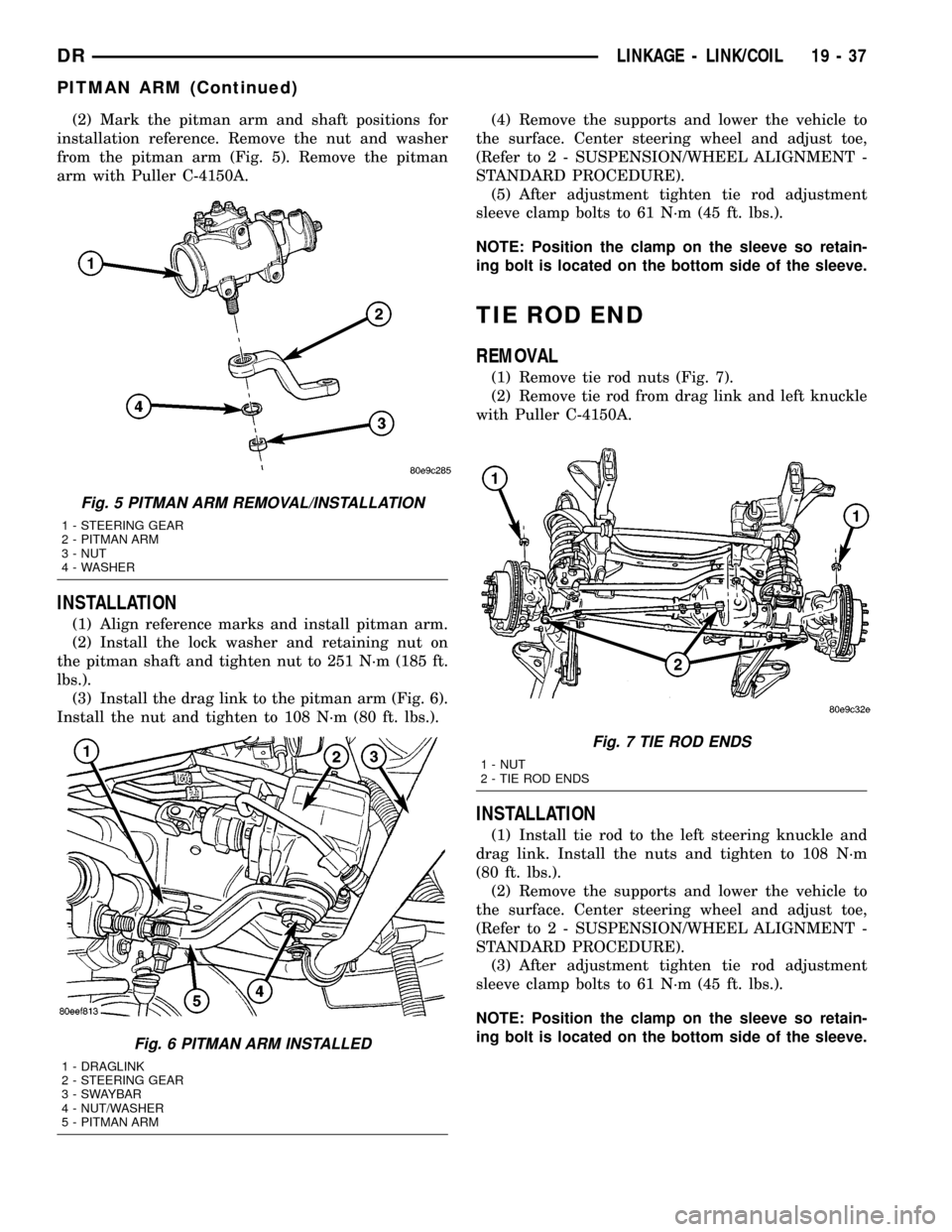
(2) Mark the pitman arm and shaft positions for
installation reference. Remove the nut and washer
from the pitman arm (Fig. 5). Remove the pitman
arm with Puller C-4150A.
INSTALLATION
(1) Align reference marks and install pitman arm.
(2) Install the lock washer and retaining nut on
the pitman shaft and tighten nut to 251 N´m (185 ft.
lbs.).
(3) Install the drag link to the pitman arm (Fig. 6).
Install the nut and tighten to 108 N´m (80 ft. lbs.).(4) Remove the supports and lower the vehicle to
the surface. Center steering wheel and adjust toe,
(Refer to 2 - SUSPENSION/WHEEL ALIGNMENT -
STANDARD PROCEDURE).
(5) After adjustment tighten tie rod adjustment
sleeve clamp bolts to 61 N´m (45 ft. lbs.).
NOTE: Position the clamp on the sleeve so retain-
ing bolt is located on the bottom side of the sleeve.
TIE ROD END
REMOVAL
(1) Remove tie rod nuts (Fig. 7).
(2) Remove tie rod from drag link and left knuckle
with Puller C-4150A.
INSTALLATION
(1) Install tie rod to the left steering knuckle and
drag link. Install the nuts and tighten to 108 N´m
(80 ft. lbs.).
(2) Remove the supports and lower the vehicle to
the surface. Center steering wheel and adjust toe,
(Refer to 2 - SUSPENSION/WHEEL ALIGNMENT -
STANDARD PROCEDURE).
(3) After adjustment tighten tie rod adjustment
sleeve clamp bolts to 61 N´m (45 ft. lbs.).
NOTE: Position the clamp on the sleeve so retain-
ing bolt is located on the bottom side of the sleeve.
Fig. 5 PITMAN ARM REMOVAL/INSTALLATION
1 - STEERING GEAR
2 - PITMAN ARM
3 - NUT
4 - WASHER
Fig. 6 PITMAN ARM INSTALLED
1 - DRAGLINK
2 - STEERING GEAR
3 - SWAYBAR
4 - NUT/WASHER
5 - PITMAN ARM
Fig. 7 TIE ROD ENDS
1 - NUT
2 - TIE ROD ENDS
DRLINKAGE - LINK/COIL 19 - 37
PITMAN ARM (Continued)
Page 2306 of 2627

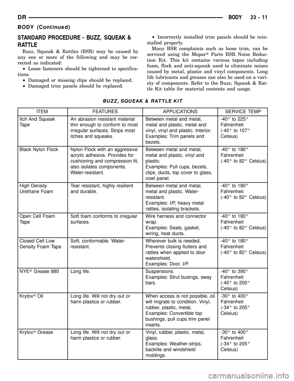
STANDARD PROCEDURE - BUZZ, SQUEAK &
RATTLE
Buzz, Squeak & Rattles (BSR) may be caused by
any one or more of the following and may be cor-
rected as indicated:
²Loose fasteners should be tightened to specifica-
tions.
²Damaged or missing clips should be replaced.
²Damaged trim panels should be replaced.²Incorrectly installed trim panels should be rein-
stalled properly.
Many BSR complaints such as loose trim, can be
serviced using the MopartParts BSR Noise Reduc-
tion Kit. This kit contains various tapes including
foam, flock and anti-squeak used to eliminate noises
caused by metal, plastic and vinyl components. Long
life lubricants and greases can also be used on a vari-
ety of components. Refer to the Buzz, Squeak & Rat-
tle Kit table for material contents and usage.
BUZZ, SQUEAK & RATTLE KIT
ITEM FEATURES APPLICATIONS SERVICE TEMP
Itch And Squeak
TapeAn abrasion resistant material
thin enough to conform to most
irregular surfaces. Stops most
itches and squeaks.Between metal and metal,
metal and plastic, metal and
vinyl, vinyl and plastic. Interior.
Examples: Trim panels and
bezels.-40É to 225É
Fahrenheit
(-40É to 107É
Celsius)
Black Nylon Flock Nylon Flock with an aggressive
acrylic adhesive. Provides for
cushioning and compression fit,
also isolates components.
Water-resistant.Between metal and metal,
metal and plastic, vinyl and
plastic.
Examples: Pull cups, bezels,
clips, ducts, top cover to glass,
cowl panel.-40É to 180É
Fahrenheit
(-40É to 82É Celsius)
High Density
Urethane FoamTear resistant, highly resilient
and durable.Between metal and metal,
metal and plastic. Water-
resistant.
Examples: I/P, heavy metal
rattles, isolating brackets.-40É to 180É
Fahrenheit
(-40É to 82É Celsius)
Open Cell Foam
TapeSoft foam conforms to irregular
surfaces.Wire harness and connector
wrap.
Examples: Seals, gasket,
wiring, heat ducts.-40É to 180É
Fahrenheit
(-40É to 82É Celsius)
Closed Cell Low
Density Foam TapeSoft, conformable. Water-
resistant.Wherever bulk is needed.
Prevents closing flutters and
rattles when applied to door
watershield.
Examples: Door, I/P.-40É to 180É
Fahrenheit
(-40É to 82É Celsius)
NYETGrease 880 Long life. Suspensions.
Examples: Strut busings, sway
bars.-40É to 390É
Fahrenheit
(-40É to 200É
Celsius)
KrytoxTOil Long life. Will not dry out or
harm plastics or rubber.When access is not possible, oil
will migrate to condition. Vinyl,
rubber, plastic, metal.
Examples: Convertible top
bushings, pull cups trim panel
inserts.-30É to 400É
Fahrenheit
(-34É to 205É
Celsius)
KrytoxTGrease Long life. Will not dry out or
harm plastics or rubber.Vinyl, rubber, plastic, metal,
glass.
Examples: Weather-strips,
backlite and windshield
moldings.-30É to 400É
Fahrenheit
(-34É to 205É
Celsius)
DRBODY 23 - 11
BODY (Continued)