1998 DODGE RAM 1500 4WD
[x] Cancel search: 4WDPage 1050 of 2627

8W-80 CONNECTOR PIN-OUTS
Component Page
4WD Switch (Manual Transfer Case)..... 8W-80-5
A/C Compressor Clutch (Diesel)......... 8W-80-5
A/C Compressor Clutch (Gas)........... 8W-80-5
A/C Heater Control C1................ 8W-80-5
A/C Heater Control C2................ 8W-80-6
A/C Pressure Transducer (Diesel)........ 8W-80-6
A/C Pressure Transducer (NGC)......... 8W-80-6
Accelerator Pedal Position Sensor (5.7L) . . 8W-80-6
Accelerator Pedal Position Sensor
(Diesel M/T)...................... 8W-80-7
Accelerator Pedel Position Sensor
(Diesel A/T)....................... 8W-80-7
Adjustable Pedal Motor (Except Memory) . 8W-80-7
Adjustable Pedal Switch (Except Memory) . 8W-80-8
Airbag Control Module C1............. 8W-80-8
Airbag Control Module C2............. 8W-80-9
Airbag-Left Curtain.................. 8W-80-9
Airbag-Passenger On/Off Switch....... 8W-80-10
Airbag-Passenger Squib.............. 8W-80-10
Airbag-Right Curtain................ 8W-80-10
Ambient Temperature Sensor.......... 8W-80-10
Amplifier Audio C1 (Premium)......... 8W-80-11
Amplifier Audio C2 (Premium)......... 8W-80-11
Ashtray Lamp...................... 8W-80-11
Automatic Day/Night Mirror C1 (Except
Base).......................... 8W-80-12
Automatic Day/Night Mirror C2
(Telematics)..................... 8W-80-12
Back-Up Lamp Switch............... 8W-80-12
Battery Temperature Sensor........... 8W-80-12
Blend Door Actuator (Single Zone)...... 8W-80-13
Blower Motor...................... 8W-80-13
Blower Motor Resistor Block.......... 8W-80-13
Brake Fluid Level Switch............. 8W-80-13
Brake Lamp Switch................. 8W-80-13
Brake Transmission Shift Interlock
Solenoid........................ 8W-80-14
C102 (NGC)....................... 8W-80-14
C103............................. 8W-80-14
C106 (5.7L A/T).................... 8W-80-14
C106 (5.7L A/T).................... 8W-80-15
C107 (5.7L)........................ 8W-80-15
C107 (5.7L)........................ 8W-80-16
C108 (Diesel)...................... 8W-80-16
C108 (Diesel)...................... 8W-80-16
C109 (Diesel)...................... 8W-80-17
C109 (Diesel)...................... 8W-80-17
C110 (Diesel)...................... 8W-80-17
C110 (Diesel)...................... 8W-80-18
C112 (Diesel M/T)................... 8W-80-18
C112 (Diesel M/T)................... 8W-80-18
C112 (Diesel A/T)................... 8W-80-18Component Page
C112 (Diesel A/T)................... 8W-80-19
C130 (Diesel)...................... 8W-80-19
C131 (4.7L Electronic Transfer Case).... 8W-80-20
C131 (4.7L Electronic Transfer Case).... 8W-80-20
C131 (5.7L/Diesel).................. 8W-80-20
C131 (5.7L/Diesel).................. 8W-80-21
C131 (3.7L/4.7L Except Electronic
Transfer Case)................... 8W-80-21
C131 (3.7L/4.7L Except Electronic
Transfer Case)................... 8W-80-22
C200............................. 8W-80-22
C200............................. 8W-80-23
C201............................. 8W-80-23
C201............................. 8W-80-23
C202............................. 8W-80-24
C202............................. 8W-80-24
C206............................. 8W-80-24
C206............................. 8W-80-24
C207............................. 8W-80-24
C207............................. 8W-80-25
C216............................. 8W-80-25
C216............................. 8W-80-25
C217............................. 8W-80-26
C217............................. 8W-80-26
C218............................. 8W-80-26
C218............................. 8W-80-27
C219............................. 8W-80-27
C219............................. 8W-80-29
C220............................. 8W-80-30
C220............................. 8W-80-31
C250 (Hands Free).................. 8W-80-31
C250 (Hands Free).................. 8W-80-32
C301............................. 8W-80-32
C301............................. 8W-80-32
C301............................. 8W-80-33
C302............................. 8W-80-33
C302 (SLT)........................ 8W-80-34
C304............................. 8W-80-34
C304............................. 8W-80-34
C305 (SLT)........................ 8W-80-35
C305 (SLT)........................ 8W-80-35
C306............................. 8W-80-36
C306............................. 8W-80-36
C308............................. 8W-80-36
C308............................. 8W-80-37
C309............................. 8W-80-37
C309............................. 8W-80-37
C311 ............................. 8W-80-38
C311 ............................. 8W-80-38
C313............................. 8W-80-38
C313............................. 8W-80-39
C315............................. 8W-80-39
DR8W-80 CONNECTOR PIN-OUTS 8W - 80 - 1
Page 1054 of 2627
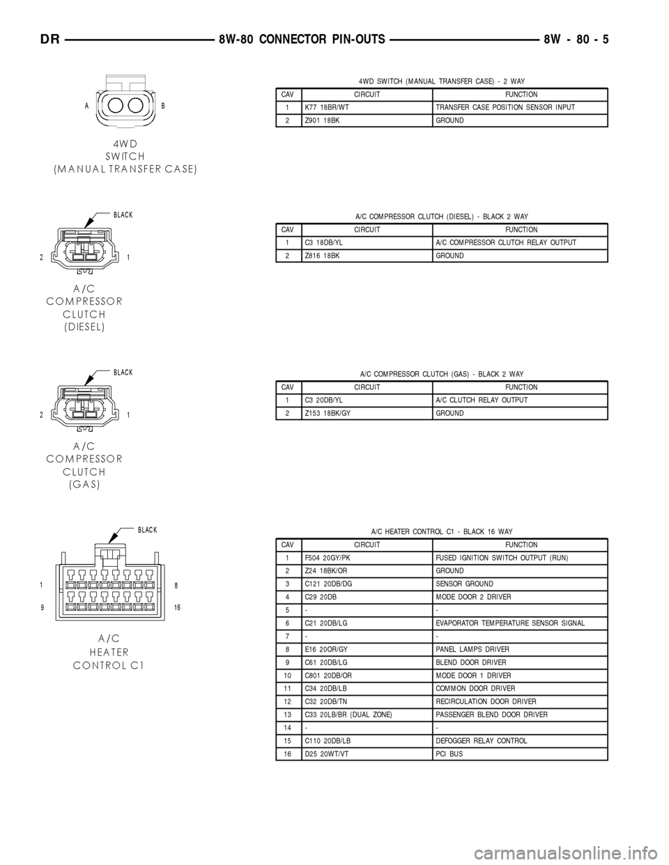
4WD SWITCH (MANUAL TRANSFER CASE)-2WAY
CAV CIRCUIT FUNCTION
1 K77 18BR/WT TRANSFER CASE POSITION SENSOR INPUT
2 Z901 18BK GROUND
A/C COMPRESSOR CLUTCH (DIESEL) - BLACK 2 WAY
CAV CIRCUIT FUNCTION
1 C3 18DB/YL A/C COMPRESSOR CLUTCH RELAY OUTPUT
2 Z816 18BK GROUND
A/C COMPRESSOR CLUTCH (GAS) - BLACK 2 WAY
CAV CIRCUIT FUNCTION
1 C3 20DB/YL A/C CLUTCH RELAY OUTPUT
2 Z153 18BK/GY GROUND
A/C HEATER CONTROL C1 - BLACK 16 WAY
CAV CIRCUIT FUNCTION
1 F504 20GY/PK FUSED IGNITION SWITCH OUTPUT (RUN)
2 Z24 18BK/OR GROUND
3 C121 20DB/DG SENSOR GROUND
4 C29 20DB MODE DOOR 2 DRIVER
5- -
6 C21 20DB/LG EVAPORATOR TEMPERATURE SENSOR SIGNAL
7- -
8 E16 20OR/GY PANEL LAMPS DRIVER
9 C61 20DB/LG BLEND DOOR DRIVER
10 C801 20DB/OR MODE DOOR 1 DRIVER
11 C34 20DB/LB COMMON DOOR DRIVER
12 C32 20DB/TN RECIRCULATION DOOR DRIVER
13 C33 20LB/BR (DUAL ZONE) PASSENGER BLEND DOOR DRIVER
14 - -
15 C110 20DB/LB DEFOGGER RELAY CONTROL
16 D25 20WT/VT PCI BUS
DR8W-80 CONNECTOR PIN-OUTS 8W - 80 - 5
Page 1149 of 2627
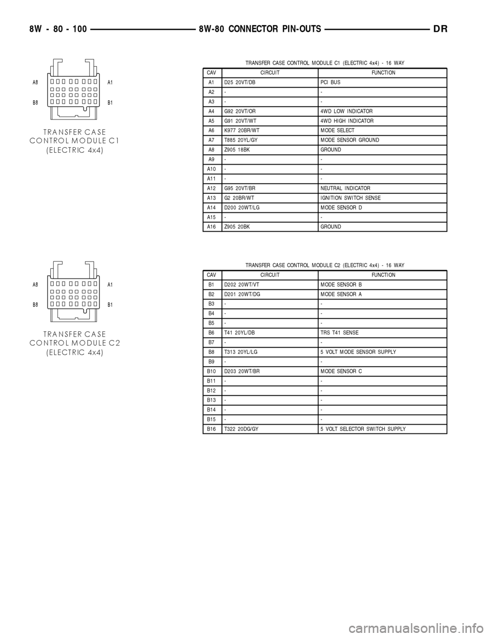
TRANSFER CASE CONTROL MODULE C1 (ELECTRIC 4x4) - 16 WAY
CAV CIRCUIT FUNCTION
A1 D25 20VT/DB PCI BUS
A2 - -
A3 - -
A4 G92 20VT/OR 4WD LOW INDICATOR
A5 G91 20VT/WT 4WD HIGH INDICATOR
A6 K977 20BR/WT MODE SELECT
A7 T885 20YL/GY MODE SENSOR GROUND
A8 Z905 18BK GROUND
A9 - -
A10 - -
A11 - -
A12 G95 20VT/BR NEUTRAL INDICATOR
A13 G2 20BR/WT IGNITION SWITCH SENSE
A14 D200 20WT/LG MODE SENSOR D
A15 - -
A16 Z905 20BK GROUND
TRANSFER CASE CONTROL MODULE C2 (ELECTRIC 4x4) - 16 WAY
CAV CIRCUIT FUNCTION
B1 D202 20WT/VT MODE SENSOR B
B2 D201 20WT/DG MODE SENSOR A
B3 - -
B4 - -
B5 - -
B6 T41 20YL/DB TRS T41 SENSE
B7 - -
B8 T313 20YL/LG 5 VOLT MODE SENSOR SUPPLY
B9 - -
B10 D203 20WT/BR MODE SENSOR C
B11 - -
B12 - -
B13 - -
B14 - -
B15 - -
B16 T322 20DG/GY 5 VOLT SELECTOR SWITCH SUPPLY
8W - 80 - 100 8W-80 CONNECTOR PIN-OUTSDR
Page 1150 of 2627
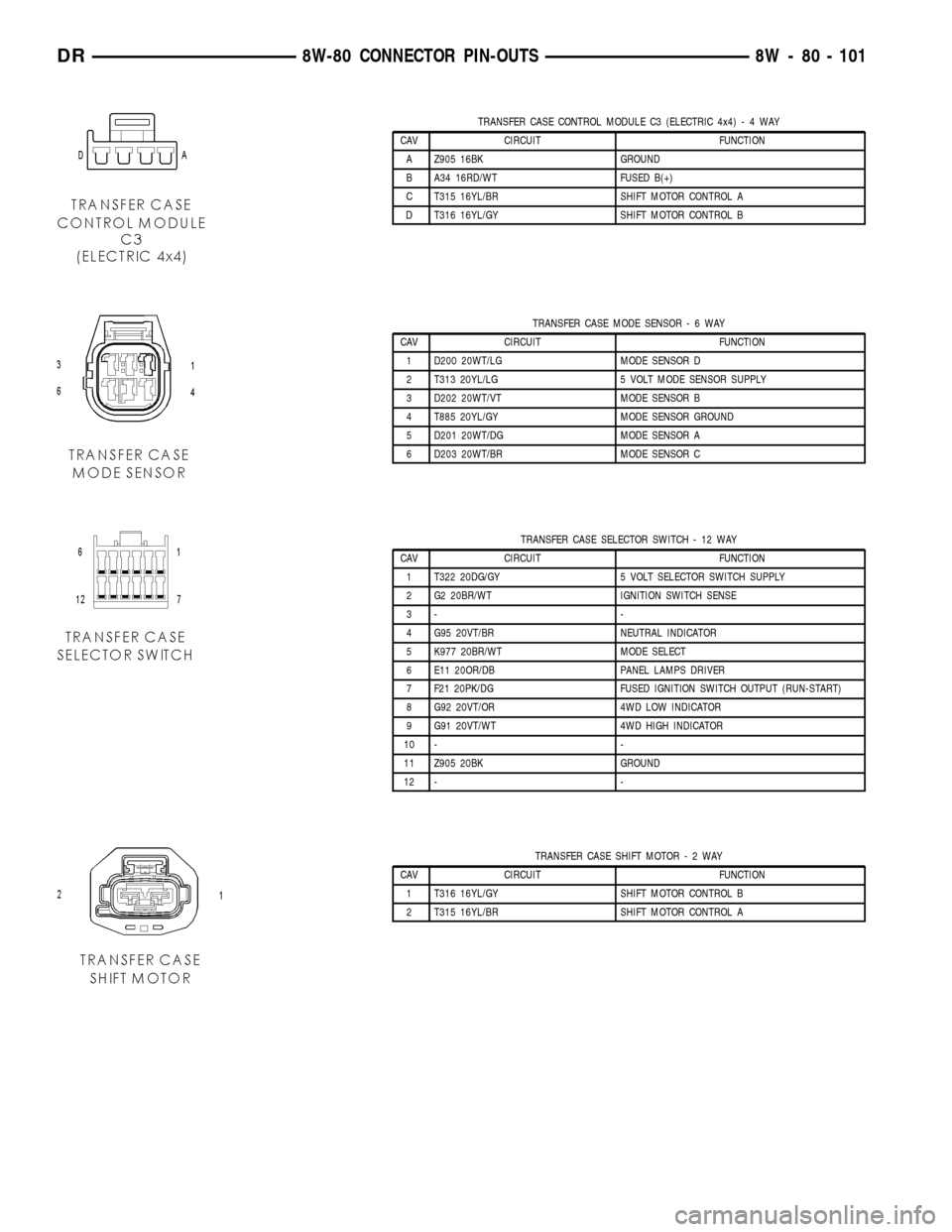
TRANSFER CASE CONTROL MODULE C3 (ELECTRIC 4x4)-4WAY
CAV CIRCUIT FUNCTION
A Z905 16BK GROUND
B A34 16RD/WT FUSED B(+)
C T315 16YL/BR SHIFT MOTOR CONTROL A
D T316 16YL/GY SHIFT MOTOR CONTROL B
TRANSFER CASE MODE SENSOR-6WAY
CAV CIRCUIT FUNCTION
1 D200 20WT/LG MODE SENSOR D
2 T313 20YL/LG 5 VOLT MODE SENSOR SUPPLY
3 D202 20WT/VT MODE SENSOR B
4 T885 20YL/GY MODE SENSOR GROUND
5 D201 20WT/DG MODE SENSOR A
6 D203 20WT/BR MODE SENSOR C
TRANSFER CASE SELECTOR SWITCH - 12 WAY
CAV CIRCUIT FUNCTION
1 T322 20DG/GY 5 VOLT SELECTOR SWITCH SUPPLY
2 G2 20BR/WT IGNITION SWITCH SENSE
3- -
4 G95 20VT/BR NEUTRAL INDICATOR
5 K977 20BR/WT MODE SELECT
6 E11 20OR/DB PANEL LAMPS DRIVER
7 F21 20PK/DG FUSED IGNITION SWITCH OUTPUT (RUN-START)
8 G92 20VT/OR 4WD LOW INDICATOR
9 G91 20VT/WT 4WD HIGH INDICATOR
10 - -
11 Z905 20BK GROUND
12 - -
TRANSFER CASE SHIFT MOTOR-2WAY
CAV CIRCUIT FUNCTION
1 T316 16YL/GY SHIFT MOTOR CONTROL B
2 T315 16YL/BR SHIFT MOTOR CONTROL A
DR8W-80 CONNECTOR PIN-OUTS 8W - 80 - 101
Page 1154 of 2627
8W-91 CONNECTOR/GROUND/SPLICE LOCATION
TABLE OF CONTENTS
page
CONNECTOR/GROUND/SPLICE LOCATION
DESCRIPTION..........................1
CONNECTOR/GROUND/SPLICE
LOCATION
DESCRIPTION
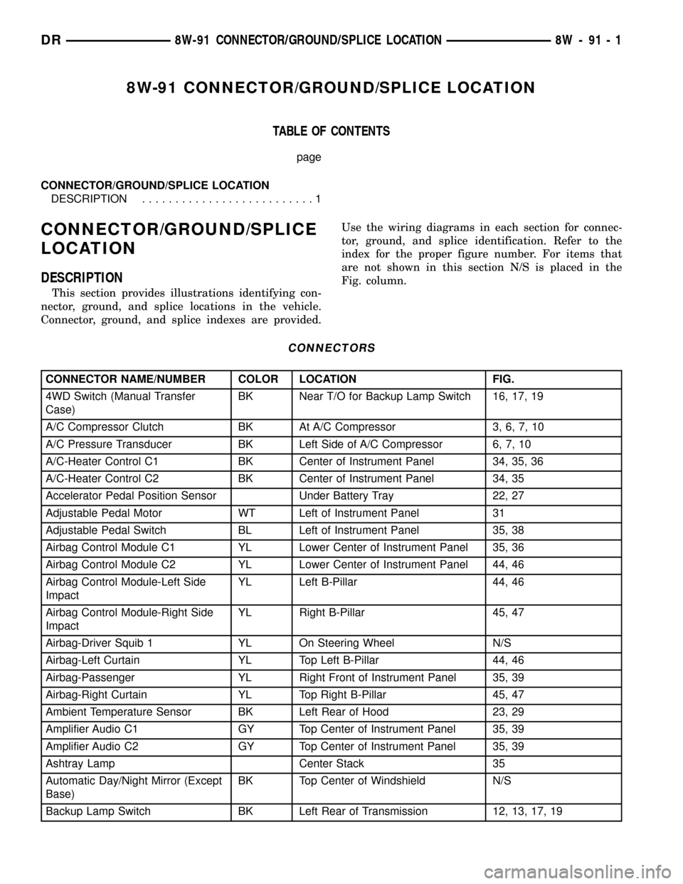
This section provides illustrations identifying con-
nector, ground, and splice locations in the vehicle.
Connector, ground, and splice indexes are provided.Use the wiring diagrams in each section for connec-
tor, ground, and splice identification. Refer to the
index for the proper figure number. For items that
are not shown in this section N/S is placed in the
Fig. column.
CONNECTORS
CONNECTOR NAME/NUMBER COLOR LOCATION FIG.
4WD Switch (Manual Transfer
Case)BK Near T/O for Backup Lamp Switch 16, 17, 19
A/C Compressor Clutch BK At A/C Compressor 3, 6, 7, 10
A/C Pressure Transducer BK Left Side of A/C Compressor 6, 7, 10
A/C-Heater Control C1 BK Center of Instrument Panel 34, 35, 36
A/C-Heater Control C2 BK Center of Instrument Panel 34, 35
Accelerator Pedal Position Sensor Under Battery Tray 22, 27
Adjustable Pedal Motor WT Left of Instrument Panel 31
Adjustable Pedal Switch BL Left of Instrument Panel 35, 38
Airbag Control Module C1 YL Lower Center of Instrument Panel 35, 36
Airbag Control Module C2 YL Lower Center of Instrument Panel 44, 46
Airbag Control Module-Left Side
ImpactYL Left B-Pillar 44, 46
Airbag Control Module-Right Side
ImpactYL Right B-Pillar 45, 47
Airbag-Driver Squib 1 YL On Steering Wheel N/S
Airbag-Left Curtain YL Top Left B-Pillar 44, 46
Airbag-Passenger YL Right Front of Instrument Panel 35, 39
Airbag-Right Curtain YL Top Right B-Pillar 45, 47
Ambient Temperature Sensor BK Left Rear of Hood 23, 29
Amplifier Audio C1 GY Top Center of Instrument Panel 35, 39
Amplifier Audio C2 GY Top Center of Instrument Panel 35, 39
Ashtray Lamp Center Stack 35
Automatic Day/Night Mirror (Except
Base)BK Top Center of Windshield N/S
Backup Lamp Switch BK Left Rear of Transmission 12, 13, 17, 19
DR8W-91 CONNECTOR/GROUND/SPLICE LOCATION 8W - 91 - 1
Page 1281 of 2627

FRONT MOUNT
REMOVAL
2WD
(1) Disconnect the negative cable from the battery.
CAUTION: Remove the viscous fan before raising
engine. Failure to do so may cause damage to the
fan blade, fan clutch and fan shroud.
(2) Remove the viscous fan (Refer to 7 - COOL-
ING/ENGINE/FAN DRIVE VISCOUS CLUTCH -
REMOVAL).
(3) Raise the vehicle.
(4) Remove the engine oil filter.
(5) Remove the oil drain trough.
(6)
Support the engine with a suitable jack and a
block of wood across the full width of the engine oil pan.
(7) Support the front axle with a suitable jack.
(8) Remove the (4) bolts that attach the engine
mounts to the front axle.
(9) Remove the (3) bolts that attach the front axle
to the left engine bracket.
(10) Lower the front axle.
(11) Remove the through bolts(12) Raise the engine far enough to be able to
remove the left and right engine mounts.
(13) Remove the (8) mount to engine attaching
bolts
(14) Remove the engine mounts.
4WD
(1) Disconnect the negative cable from the battery.
CAUTION: Remove the viscous fan before raising
engine. Failure to do so may cause damage to the
fan blade, fan clutch and fan shroud.
(2) Remove the viscous fan (Refer to 7 - COOL-
ING/ENGINE/FAN DRIVE VISCOUS CLUTCH -
REMOVAL).
(3) Raise the vehicle.
(4) Remove the skid plate.
(5) Remove the front crossmember.
(6) Remove the engine oil filter.
(7) Remove the oil drain trough.
(8) Support the engine with a suitable jack and a
block of wood across the full width of the engine oil
pan.
(9) Support the front axle with a suitable jack.
(10) Remove the (4) bolts that attach the engine
mounts to the front axle (Fig. 66).
Fig. 66 ENGINE INSULATOR MOUNTS 4X4
1 - RH INSULATOR TO AXLE BOLT
2 - NUT
3 - PINION SUPPORT MOUNT
4 - LH INSULATOR MOUNT5 - LH INSULATOR TO AXLE BOLT
6 - FRONT AXLE
7 - NUT
8 - RH INSULATOR MOUNT
9 - 58 ENGINE - 3.7LDR
Page 1282 of 2627
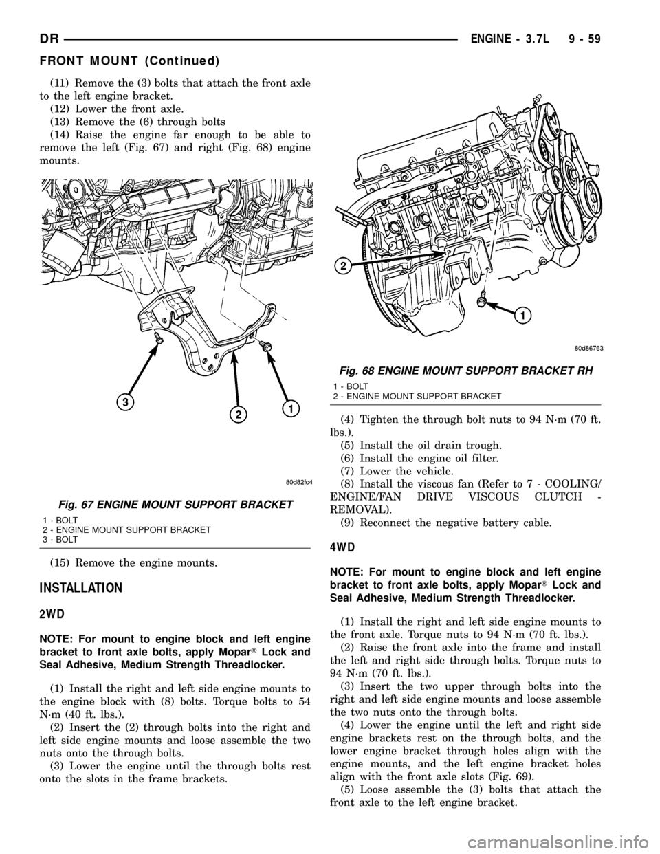
(11) Remove the (3) bolts that attach the front axle
to the left engine bracket.
(12) Lower the front axle.
(13) Remove the (6) through bolts
(14) Raise the engine far enough to be able to
remove the left (Fig. 67) and right (Fig. 68) engine
mounts.
(15) Remove the engine mounts.
INSTALLATION
2WD
NOTE: For mount to engine block and left engine
bracket to front axle bolts, apply MoparTLock and
Seal Adhesive, Medium Strength Threadlocker.
(1) Install the right and left side engine mounts to
the engine block with (8) bolts. Torque bolts to 54
N´m (40 ft. lbs.).
(2) Insert the (2) through bolts into the right and
left side engine mounts and loose assemble the two
nuts onto the through bolts.
(3) Lower the engine until the through bolts rest
onto the slots in the frame brackets.(4) Tighten the through bolt nuts to 94 N´m (70 ft.
lbs.).
(5) Install the oil drain trough.
(6) Install the engine oil filter.
(7) Lower the vehicle.
(8) Install the viscous fan (Refer to 7 - COOLING/
ENGINE/FAN DRIVE VISCOUS CLUTCH -
REMOVAL).
(9) Reconnect the negative battery cable.
4WD
NOTE: For mount to engine block and left engine
bracket to front axle bolts, apply MoparTLock and
Seal Adhesive, Medium Strength Threadlocker.
(1) Install the right and left side engine mounts to
the front axle. Torque nuts to 94 N´m (70 ft. lbs.).
(2) Raise the front axle into the frame and install
the left and right side through bolts. Torque nuts to
94 N´m (70 ft. lbs.).
(3) Insert the two upper through bolts into the
right and left side engine mounts and loose assemble
the two nuts onto the through bolts.
(4) Lower the engine until the left and right side
engine brackets rest on the through bolts, and the
lower engine bracket through holes align with the
engine mounts, and the left engine bracket holes
align with the front axle slots (Fig. 69).
(5) Loose assemble the (3) bolts that attach the
front axle to the left engine bracket.
Fig. 67 ENGINE MOUNT SUPPORT BRACKET
1 - BOLT
2 - ENGINE MOUNT SUPPORT BRACKET
3 - BOLT
Fig. 68 ENGINE MOUNT SUPPORT BRACKET RH
1 - BOLT
2 - ENGINE MOUNT SUPPORT BRACKET
DRENGINE - 3.7L 9 - 59
FRONT MOUNT (Continued)
Page 1369 of 2627

CAUTION: The structural cover must be held tightly
against both the engine and the transmission bell
housing during tightening sequence. Failure to do
so may cause damage to the cover.
(4) Starting with the two rear cover-to-engine
bolts, tighten bolts (1) (Fig. 86) to 54 N´m (40 ft. lbs.),
then tighten bolts (2) (Fig. 86) and (3) to 54 N´m ( 40
ft. lbs.) in the sequence shown.
(5) Install the exhaust pipe on left hand exhaust
manifold.
(6) Tighten exhaust manifold-to-exhaust pipe
retaining bolts to 20±26 N´m (15±20 ft. lbs.).
FRONT MOUNT
REMOVAL
2WD
(1) Disconnect the negative cable from the battery.
CAUTION: Remove the viscous fan before raising
engine. Failure to do so may cause damage to the
fan blade, fan clutch and fan shroud.(2) Remove the viscous fan (Refer to 7 - COOL-
ING/ENGINE/FAN DRIVE VISCOUS CLUTCH -
REMOVAL).
(3) Raise the vehicle.
(4) Remove the engine oil filter.
(5) Remove the oil drain trough.
(6) Support the engine with a suitable jack and a
block of wood across the full width of the engine oil
pan.
(7) Support the front axle with a suitable jack.
(8) Remove the (4) bolts that attach the engine
mounts to the front axle.
(9) Remove the (3) bolts that attach the front axle
to the left engine bracket.
(10) Lower the front axle.
(11) Remove the through bolts
(12) Raise the engine far enough to be able to
remove the left and right engine mounts.
(13) Remove the (8) mount to engine attaching
bolts
(14) Remove the engine mounts.
4WD
(1) Disconnect the negative cable from the battery.
(2) Remove the viscous fan.
(3) Raise the vehicle.
(4) Remove the skid plate.
(5) Remove the front crossmember.
(6) Remove the engine oil filter.
(7) Remove the oil drain trough.
(8) Support the engine with a suitable jack and a
block of wood across the full width of the engine oil
pan.
(9) Support the front axle with a suitable jack.
(10) Remove the (4) bolts that attach the engine
mounts to the front axle (Fig. 87).
(11) Remove the (3) bolts that attach the front axle
to the left engine bracket.
(12) Lower the front axle.
(13) Remove the (6) through bolts
Fig. 86 Structural Cover
1 - BOLT
2 - BOLT
3 - BOLT
9 - 146 ENGINE - 4.7LDR
STRUCTURAL COVER (Continued)