1998 DODGE RAM 1500 check engine
[x] Cancel search: check enginePage 26 of 2627

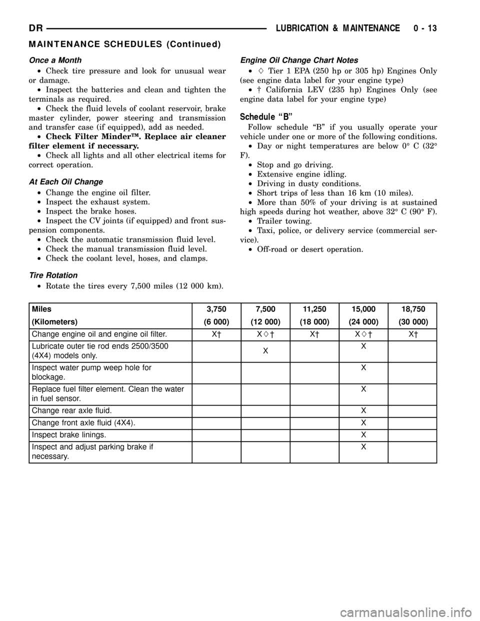
Once a Month
²Check tire pressure and look for unusual wear
or damage.
²Inspect the batteries and clean and tighten the
terminals as required.
²Check the fluid levels of coolant reservoir, brake
master cylinder, power steering and transmission
and transfer case (if equipped), add as needed.
²Check Filter MinderŸ. Replace air cleaner
filter element if necessary.
²Check all lights and all other electrical items for
correct operation.
At Each Oil Change
²Change the engine oil filter.
²Inspect the exhaust system.
²Inspect the brake hoses.
²Inspect the CV joints (if equipped) and front sus-
pension components.
²Check the automatic transmission fluid level.
²Check the manual transmission fluid level.
²Check the coolant level, hoses, and clamps.
Tire Rotation
²Rotate the tires every 7,500 miles (12 000 km).
Engine Oil Change Chart Notes
²LTier 1 EPA (250 hp or 305 hp) Engines Only
(see engine data label for your engine type)
²² California LEV (235 hp) Engines Only (see
engine data label for your engine type)
Schedule ªBº
Follow schedule ªBº if you usually operate your
vehicle under one or more of the following conditions.
²Day or night temperatures are below 0É C (32É
F).
²Stop and go driving.
²Extensive engine idling.
²Driving in dusty conditions.
²Short trips of less than 16 km (10 miles).
²More than 50% of your driving is at sustained
high speeds during hot weather, above 32É C (90É F).
²Trailer towing.
²Taxi, police, or delivery service (commercial ser-
vice).
²Off-road or desert operation.
Miles 3,750 7,500 11,250 15,000 18,750
(Kilometers) (6 000) (12 000) (18 000) (24 000) (30 000)
Change engine oil and engine oil filter. X² XL²X²XL²X²
Lubricate outer tie rod ends 2500/3500
(4X4) models only.XX
Inspect water pump weep hole for
blockage.X
Replace fuel filter element. Clean the water
in fuel sensor.X
Change rear axle fluid. X
Change front axle fluid (4X4). X
Inspect brake linings.X
Inspect and adjust parking brake if
necessary.X
DRLUBRICATION & MAINTENANCE 0 - 13
MAINTENANCE SCHEDULES (Continued)
Page 27 of 2627

Miles 22,500 26,250 30,000 33,750 37,500
(Kilometers) (36 000) (42 000) (48 000) (54 000) (60 000)
Change engine oil and engine oil filter. XL²X²XL²X² XL²
Lubricate outer tie rod ends 2500/3500
(4X4) models only.XXX
Inspect drive belt, replace as required. X
Inspect fan hub. X
Inspect damper. X
Inspect water pump weep hole for
blockage.X
Replace fuel filter element. Clean the water
in fuel sensor.X
Change rear axle fluid. X
Change front axle fluid (4X4). X
Check transfer case fluid level (4X4). X
Drain and refill automatic transmission fluid.
Replace filter and adjust bands.X
Miles 41,250 45,000 48,750 52,500 56,250
(Kilometers) (66 000) (72 000) (78 000) (84 000) (90 000)
Change engine oil and engine oil filter. X² XL²X²XL²X²
Lubricate outer tie rod ends 2500/3500
(4X4) models only.XX
Inspect drive belt, replace as required. X
Inspect water pump weep hole for
blockage.X
Replace fuel filter element. Clean the water
in fuel sensor.X
Inspect brake linings. X
Inspect and adjust parking brake if
necessary.X
Change rear axle fluid. X
Change front axle fluid (4X4). X
0 - 14 LUBRICATION & MAINTENANCEDR
MAINTENANCE SCHEDULES (Continued)
Page 28 of 2627

Miles 60,000 63,750 67,500 71,250 75,000
(Kilometers) (96 000) (102 000) (108 000) (114 000) (120 000)
Change engine oil and engine oil filter. XL²X²XL²X² XL²
Lubricate outer tie rod ends 2500/3500
(4X4) models only.XXX
Inspect drive belt, replace as required. X
Inspect fan hub. X
Inspect damper. X
Inspect water pump weep hole for
blockage.XX
Replace fuel filter element. Clean the water
in fuel sensor.XX
Inspect front wheel bearings. X
Change rear axle fluid. X X
Change front axle fluid (4X4). X X
Inspect brake linings. X X
Inspect and adjust parking brake if
necessary.XX
Drain and refill transfer case fluid (4X4). X
Drain and refill automatic transmission fluid.
Replace filter and adjust bands.X
Miles 78,750 82,500 86,250 90,000 93,750
(Kilometers) (126 000) (132 000) (138 000) (144 000) (150 000)
Change engine oil and engine oil filter. X² XL²X²XL²X²
Lubricate outer tie rod ends 2500/3500
(4X4) models only.XX
Inspect drive belt, replace as required. X
Change rear axle fluid. X
Change front axle fluid (4X4). X
Check transfer case fluid level (4X4). X
Inspect fan hub.X
Inspect damper.X
Inspect water pump weep hole for
blockage.X
Replace fuel filter element. Clean the water
in fuel sensor.X
Inspect front wheel bearings. X
Inspect brake linings.X
Inspect and adjust parking brake if
necessary.X
Drain and refill automatic transmission fluid.
Replace filter and adjust bands.X
DRLUBRICATION & MAINTENANCE 0 - 15
MAINTENANCE SCHEDULES (Continued)
Page 30 of 2627

²LTier 1 EPA (250 hp or 305 hp) Engines Only
(see engine data label for your engine type)
²² California LEV (235 hp) Engines Only (see
engine data label for your engine type)Inspection and service should also be performed
anytime a malfunction is observed or suspected.
Schedule ªAº
Miles 7,500 15,000 22,500 30,000 37,500
(Kilometers) (12 000) (24 000) (36 000) (48 000) (60 000)
[Months] [6] [12] [18] [24] [30]
Change engine oil and engine oil filter. X² XL²X²XL²X²
Lubricate outer tie rod ends 2500/3500
(4X4) models only.XXXX X
Check transfer case fluid level (4X4). X
Inspect water pump weep hole for blockage X X
Replace fuel filter element. Clean the water
in fuel sensor.XX
Inspect drive belts, replace as necessary. X
Inspect brake linings. X
Inspect and adjust parking brake if
necessary.X
Inspect fan hub.X
Inspect damper.X
Inspect front wheel bearings. X
Miles 45,000 52,500 60,000 67,500 75,000
(Kilometers) (72 000) (84 000) (96 000) (108 000) (120 000)
[Months] [36] [42] [48] [54] [60]
Change engine oil and engine oil filter. XL²X²XL²X² XL²
Lubricate outer tie rod ends 2500/3500
(4X4) models only.XXXX X
Check transfer case fluid level. X
Flush and replace engine coolant at 60
months, regardless of mileage.X
Inspect drive belts, replace as necessary. X X
Inspect water pump weep hole for blockage X X X
Replace fuel filter element. Clean the water
in fuel sensor.XX
Inspect brake linings. X X
Inspect and adjust parking brake if
necessary.XX
Inspect fan hub. X
Inspect damper. X
Inspect front wheel bearings. X
Replace fuel filter element. Clean the water
in fuel sensorX
DRLUBRICATION & MAINTENANCE 0 - 17
MAINTENANCE SCHEDULES (Continued)
Page 31 of 2627
![DODGE RAM 1500 1998 2.G Workshop Manual Miles 82,500 90,000 97,500 100,000 105,000
(Kilometers) (132 000) (144 000) (156 000) (160 000) (168 000)
[Months] [66] [72] [78] [84]
Change engine oil and engine oil filter. X² XL²X² XL²
Lubrica DODGE RAM 1500 1998 2.G Workshop Manual Miles 82,500 90,000 97,500 100,000 105,000
(Kilometers) (132 000) (144 000) (156 000) (160 000) (168 000)
[Months] [66] [72] [78] [84]
Change engine oil and engine oil filter. X² XL²X² XL²
Lubrica](/manual-img/12/5702/w960_5702-30.png)
Miles 82,500 90,000 97,500 100,000 105,000
(Kilometers) (132 000) (144 000) (156 000) (160 000) (168 000)
[Months] [66] [72] [78] [84]
Change engine oil and engine oil filter. X² XL²X² XL²
Lubricate outer tie rod ends 2500/3500
(4X4) models only.XXXX X
Flush and replace engine coolant, if not
done at 60 mos.X
Check transfer case fluid level (4X4). X
Inspect drive belt, replace as required. X
Inspect fan hub. X
Inspect damper. X
Inspect water pump weep hole for
blockage.XX
Replace fuel filter element. Clean the water
in fuel sensor.XX
Inspect front wheel bearings. X
Inspect brake linings. X
Inspect and adjust parking brake if
necessary.X
Drain and refill automatic transmission fluid.
Replace filter and adjust bands.X
Miles 112,500 120,000 127,500 135,000 142,500 150,000
(Kilometers) (181 000) (193 000) (205 000) (217 000) (229 000) (241 000)
[Months] [90] [96] [102] [108] [114] [150]
Change engine oil and engine
oil filter.X² XL²X²XL²X² XL²
Lubricate outer tie rod ends
2500/3500 (4X4) models only.XXXXX X
Flush and replace engine
coolant, if it has been 160
000 km (100, 000 miles) or 60
months since last change.X
Inspect drive belt, replace as
required.XX
Drain and refill transfer case
fluid (4X4).X
Check tranfer case fluid level
(4X4).X
Inspect fan hub. X X
Inspect damper. X X
Inspect water pump weep
hole for blockage.XXX
Replace fuel filter element.
Clean the water in fuel
sensor.XXX
0 - 18 LUBRICATION & MAINTENANCEDR
MAINTENANCE SCHEDULES (Continued)
Page 40 of 2627

angle while adjusting caster, move one pivot bolt of
the upper control arm in or out. Then move the other
pivot bolt of the upper control arm in the opposite
direction. Install special tool 8876 between the top of
the upper control arm bracket and the upper control
arm (on 1500 series 4X2 & 4X4). Install special tool
8876 between the bottom of the upper control arm
bracket pressing the tool against the frame and the
upper control arm (on 2500/3500 series 4X2) in order
to move the upper control arm outwards for proper
adjustment with the vehicle at normal ride height
(Fig. 3).
To increase positive caster angle, move the rear
position of the upper control arm inward (toward the
engine). Move the front of the upper control arm out-
ward (away from the engine) slightly until the origi-
nal camber angle is obtained using special tool 8876
to move the upper control arm for proper adjustment.
(Fig. 3)
CAMBER
Move both pivot bolts of the upper control arm
together in or out. This will change the camber angle
significantly and little effect on the caster angle
using special tool 8876 to move the upper control
arm for proper adjustment. (Fig. 3)
After adjustment is made tighten the upper control
arm nuts to proper torque specification.
TOE ADJUSTMENT
The wheel toe position adjustment is the final
adjustment.
(1) Start the engine and turn wheels both ways
before straightening the wheels. Secure the steering
wheel with the front wheels in the straight-ahead
position.
(2) Loosen the tie rod jam nuts.
NOTE: Each front wheel should be adjusted for
one-half of the total toe position specification. This
will ensure the steering wheel will be centered
when the wheels are positioned straight-ahead.
(3) Adjust the wheel toe position by turning the
inner tie rod as necessary (Fig. 4).
(4) Tighten the tie rod jam nut to 75 N´m (55 ft.
lbs.).
(5) Verify the specifications
(6) Turn off engine.
STANDARD PROCEDURE - ALIGNMENT
LINK/COIL SUSPENSION
Before each alignment reading the vehicle should
be jounced (rear first, then front). Grasp each
bumper at the center and jounce the vehicle up and
down several times. Always release the bumper inthe down position.Set the front end alignment to
specifications while the vehicle is in its NOR-
MALLY LOADED CONDITION.
CAMBER:The wheel camber angle is preset and
is not adjustable.
CASTER:Check the caster of the front axle for
correct angle. Be sure the axle is not bent or twisted.
Road test the vehicle and make left and right turn.
Observe the steering wheel return-to-center position.
Low caster will cause poor steering wheel returnabil-
ity.
Caster can be adjusted by rotating the cams on the
lower suspension arm (Fig. 5).
TOE POSITION:The wheel toe position adjust-
ment should be the final adjustment.
Fig. 4 TIE ROD END
1 - JAM NUT
2 - TIE ROD - INNER
3 - TIE ROD END - OUTER
Fig. 5 ALIGNMENT ADJUSTMENT CAM
1 - BRACKET REINFORCEMENT
2 - ADJUSTING BOLT
3 - ADJUSTMENT CAM
DRWHEEL ALIGNMENT 2 - 5
WHEEL ALIGNMENT (Continued)
Page 83 of 2627

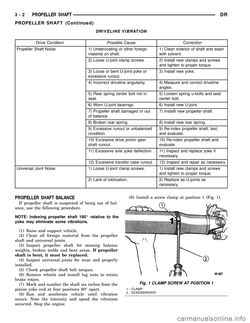
DRIVELINE VIBRATION
Drive Condition Possible Cause Correction
Propeller Shaft Noise 1) Undercoating or other foreign
material on shaft.1) Clean exterior of shaft and wash
with solvent.
2) Loose U-joint clamp screws. 2) Install new clamps and screws
and tighten to proper torque.
3) Loose or bent U-joint yoke or
excessive runout.3) Install new yoke.
4) Incorrect driveline angularity. 4) Measure and correct driveline
angles.
5) Rear spring center bolt not in
seat.5) Loosen spring u-bolts and seat
center bolt.
6) Worn U-joint bearings. 6) Install new U-joint.
7) Propeller shaft damaged or out
of balance.7) Installl new propeller shaft.
8) Broken rear spring. 8) Install new rear spring.
9) Excessive runout or unbalanced
condition.9) Re-index propeller shaft, test,
and evaluate.
10) Excessive drive pinion gear
shaft runout.10) Re-index propeller shaft and
evaluate.
11) Excessive axle yoke deflection. 11) Inspect and replace yoke if
necessary.
12) Excessive transfer case runout. 12) Inspect and repair as necessary.
Universal Joint Noise 1) Loose U-joint clamp screws. 1) Install new clamps and screws
and tighten to proper torque.
2) Lack of lubrication. 2) Replace as U-joints as
necessary.
PROPELLER SHAFT BALANCE
If propeller shaft is suspected of being out of bal-
ance, use the following procedure.
NOTE: Indexing propeller shaft 180É relative to the
yoke may eliminate some vibrations.
(1) Raise and support vehicle.
(2) Clean all foreign material from the propeller
shaft and universal joints.
(3) Inspect propeller shaft for missing balance
weights, broken welds and bent areas.If propeller
shaft is bent, it must be replaced.
(4) Inspect universal joints for wear and properly
installed.
(5) Check propeller shaft bolt torques.
(6) Remove wheels and install lug nuts to retain
brake rotors.
(7) Mark and number the shaft six inches from the
pinion yoke end at four positions 90É apart.
(8) Run and accelerate vehicle until vibration
occurs. Note the intensity and speed the vibration
occurred. Stop the engine.(9) Install a screw clamp at position 1 (Fig. 1).
Fig. 1 CLAMP SCREW AT POSITION 1
1 - CLAMP
2 - SCREWDRIVER
3 - 2 PROPELLER SHAFTDR
PROPELLER SHAFT (Continued)
Page 84 of 2627

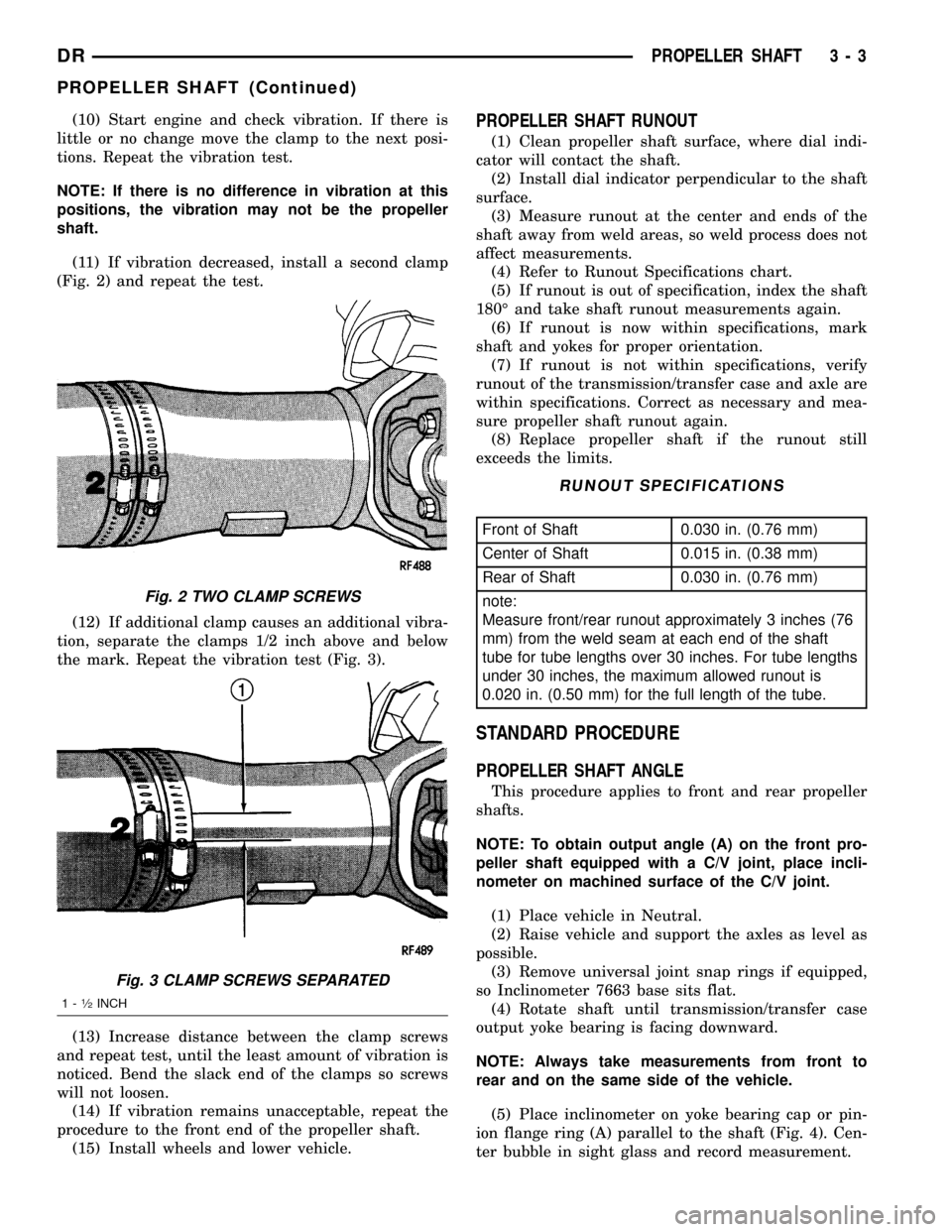
(10) Start engine and check vibration. If there is
little or no change move the clamp to the next posi-
tions. Repeat the vibration test.
NOTE: If there is no difference in vibration at this
positions, the vibration may not be the propeller
shaft.
(11) If vibration decreased, install a second clamp
(Fig. 2) and repeat the test.
(12) If additional clamp causes an additional vibra-
tion, separate the clamps 1/2 inch above and below
the mark. Repeat the vibration test (Fig. 3).
(13) Increase distance between the clamp screws
and repeat test, until the least amount of vibration is
noticed. Bend the slack end of the clamps so screws
will not loosen.
(14) If vibration remains unacceptable, repeat the
procedure to the front end of the propeller shaft.
(15) Install wheels and lower vehicle.PROPELLER SHAFT RUNOUT
(1) Clean propeller shaft surface, where dial indi-
cator will contact the shaft.
(2) Install dial indicator perpendicular to the shaft
surface.
(3) Measure runout at the center and ends of the
shaft away from weld areas, so weld process does not
affect measurements.
(4) Refer to Runout Specifications chart.
(5) If runout is out of specification, index the shaft
180É and take shaft runout measurements again.
(6) If runout is now within specifications, mark
shaft and yokes for proper orientation.
(7) If runout is not within specifications, verify
runout of the transmission/transfer case and axle are
within specifications. Correct as necessary and mea-
sure propeller shaft runout again.
(8) Replace propeller shaft if the runout still
exceeds the limits.
RUNOUT SPECIFICATIONS
Front of Shaft 0.030 in. (0.76 mm)
Center of Shaft 0.015 in. (0.38 mm)
Rear of Shaft 0.030 in. (0.76 mm)
note:
Measure front/rear runout approximately 3 inches (76
mm) from the weld seam at each end of the shaft
tube for tube lengths over 30 inches. For tube lengths
under 30 inches, the maximum allowed runout is
0.020 in. (0.50 mm) for the full length of the tube.
STANDARD PROCEDURE
PROPELLER SHAFT ANGLE
This procedure applies to front and rear propeller
shafts.
NOTE: To obtain output angle (A) on the front pro-
peller shaft equipped with a C/V joint, place incli-
nometer on machined surface of the C/V joint.
(1) Place vehicle in Neutral.
(2) Raise vehicle and support the axles as level as
possible.
(3) Remove universal joint snap rings if equipped,
so Inclinometer 7663 base sits flat.
(4) Rotate shaft until transmission/transfer case
output yoke bearing is facing downward.
NOTE: Always take measurements from front to
rear and on the same side of the vehicle.
(5) Place inclinometer on yoke bearing cap or pin-
ion flange ring (A) parallel to the shaft (Fig. 4). Cen-
ter bubble in sight glass and record measurement.
Fig. 2 TWO CLAMP SCREWS
Fig. 3 CLAMP SCREWS SEPARATED
1-1¤2INCH
DRPROPELLER SHAFT 3 - 3
PROPELLER SHAFT (Continued)