1998 DODGE RAM 1500 struts
[x] Cancel search: strutsPage 1465 of 2627
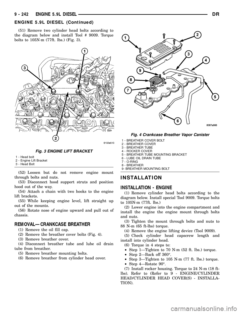
(51) Remove two cylinder head bolts according to
the diagram below and install Tool # 9009. Torque
bolts to 105N´m (77ft. lbs.) (Fig. 3).
(52) Loosen but do not remove engine mount
through bolts and nuts.
(53) Disconnect hood support struts and position
hood out of the way.
(54) Attach a chain with two hooks to the engine
lift brackets.
(55) While keeping engine level, lift straight up
out of the mounts.
(56) Rotate nose of engine upward and pull out of
chassis.
REMOVALÐCRANKCASE BREATHER
(1) Remove the oil fill cap.
(2) Remove the breather cover bolts (Fig. 4).
(3) Remove breather cover.
(4) Disconnect breather tube and lube oil drain
tube from breather.
(5) Remove breather mounting bolts.
(6) Remove breather from cylinder head cover.
INSTALLATION
INSTALLATION - ENGINE
(1) Remove cylinder head bolts according to the
diagram below. Install special Tool 9009. Torque bolts
to 105N´m (77ft. lbs.)
(2) Lower engine into the engine compartment and
install the engine the engine mount through bolts
and nuts.
(3) Tighten the mount through bolts and nuts to
88 N-m (65 ft-lbs) torque.
(4) Remove the engine lifting device (Tool 9009).
(5) Check cylinder head capscrew length and
install into cylinder head.
(6) Torque in 4 steps to:
²Step 1ÐTighten to 70 N´m (52 ft. lbs.) torque.
²Step 2ÐBack off 360É.
²Step 3ÐTighten to 105 N´m (77 ft. lbs.) torque.
²Step 4ÐRotate 90É.
(7) Install rocker housing. Torque to 24 N-m (18 ft-
lbs). Refer to (Refer to 9 - ENGINE/CYLINDER
HEAD/CYLINDER HEAD COVER(S) - INSTALLA-
TION).
Fig. 3 ENGINE LIFT BRACKET
1 - Head bolt
2 - Engine Lift Bracket
3 - Head Bolt
Fig. 4 Crankcase Breather Vapor Canister
1 - BREATHER COVER BOLT
2 - BREATHER COVER
3 - BREATHER TUBE
4 - ROCKER COVER
5 - BREATHER TUBE MOUNTING BRACKET
6 - LUBE OIL DRAIN TUBE
7 - O-RING
8 - BREATHER
9- BREATHER MOUNTING BOLT
9 - 242 ENGINE 5.9L DIESELDR
ENGINE 5.9L DIESEL (Continued)
Page 1720 of 2627

Inspect output shaft bearing retainer, the
U-shaped retainer must be flat and free of distortion.
Replace the retainer if the threads are damaged or if
the retainer is bent or cracked.
COUNTERSHAFT BEARINGS AND RACES
The countershaft bearings and races are machine
lapped during manufacture to form matched sets.
The bearings and races should not be interchanged.
NOTE: The bearing races are a permanent press fit
in the housings and are NOT serviceable. If a bear-
ing race becomes damaged, the front or rear hous-
ing must be replaced. A new countershaft bearing
will be supplied with each new housing for service
use.
REVERSE IDLER COMPONENTS
Inspect the idler gear, bearing, shaft, thrust
washer, wave washer and thrust plate. Replace the
bearing if any of the needle bearing rollers are worn,
chipped, cracked, flat-spotted or brinnelled. Also
replace the bearing if the plastic bearing cage is
damaged or distorted.
Replace thrust washer, wave washer or thrust
plate if cracked, chipped or worn. Replace idler gear
if the teeth are chipped, cracked or worn thin.
Replace shaft if worn, scored or the bolt threads are
damaged beyond repair. Replace support segment if
cracked or chipped and replace the idler attaching
bolts if the threads are damaged.
Shift Socket
Inspect the shift socket for wear or damage.
Replace the socket if the roll pin or shift shaft bores
are damaged. Minor nicks in the shift lever ball seat
in the socket can be smoothed down with 400 grit
emery or wet/dry paper. Replace the socket if the ball
seat is worn or cracked. Do not reuse the original
shift socket roll pin. Install anewpin during assem-
bly. The socket roll pin is approximately 33 mm
(1-1/4 in.) long.
Output Shaft And Geartrain
Inspect all gears for worn, cracked, chipped or bro-
ken teeth. Also check condition of the bearing bore in
each gear. The bores should be smooth and free of
surface damage. Discoloration of the gear bores is a
normal occurrence and is not a reason for replace-
ment. Replace gears only when tooth damage has
occurred or if the bores are brinnelled or severely
scored.
Inspect the shaft splines and bearings surfaces.
Minor nicks on the bearing surfaces can be smoothed
with 320/420 grit emery and final polished with cro-
cus cloth. Replace the shaft if the splines are dam-aged or bearing surfaces are deeply scored, worn or
brinnelled.
ASSEMBLY
NOTE: Sealers are used at all case joints. Use
Mopar Gasket Maker or equivalent for all case joints
and Mopar silicone sealer or equivalent for the
input shaft bearing retainer.
SYNCHRONIZER
(1) Slide sleeve onto the hub, leaving enough room
to install the spring in the hub and strut in the hub
groove.
(2) Install first spring in the hub, then install a
strut over the spring. Verify spring is seated in the
spring bore in the strut.
(3) Slide sleeve onto the hub far enough to hold
the first strut and spring in place.
(4) Place detent ball in the top of the strut, then
press the ball into place with a small screwdriver.
Work the sleeve over the ball to hold it in place.
(5) Repeat procedure for the remaining springs,
struts and balls. Use tape or rubber bands to tempo-
rarily secure each strut and ball as they are
installed.
(6) Verify the synchro three springs, struts and
detent balls are all in place (Fig. 49).
Fig. 49 SYNCHRONIZER COMPONENTS
1 - SLEEVE
2 - HUB SHOULDER
3 - SPRING (3)
4 - STRUT (3)
5 - DETENT BALL (3)
6 - HUB
DRMANUAL TRANSMISSION - NV3500 21 - 17
MANUAL TRANSMISSION - NV3500 (Continued)
Page 1750 of 2627
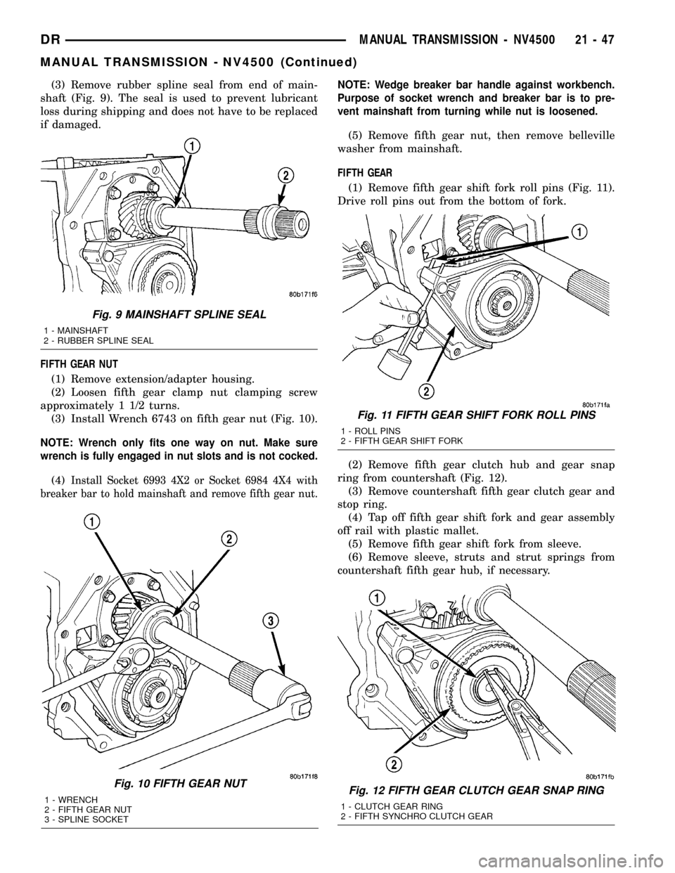
(3) Remove rubber spline seal from end of main-
shaft (Fig. 9). The seal is used to prevent lubricant
loss during shipping and does not have to be replaced
if damaged.
FIFTH GEAR NUT
(1) Remove extension/adapter housing.
(2) Loosen fifth gear clamp nut clamping screw
approximately 1 1/2 turns.
(3) Install Wrench 6743 on fifth gear nut (Fig. 10).
NOTE: Wrench only fits one way on nut. Make sure
wrench is fully engaged in nut slots and is not cocked.
(4)Install Socket 6993 4X2 or Socket 6984 4X4 with
breaker bar to hold mainshaft and remove fifth gear nut.
NOTE: Wedge breaker bar handle against workbench.
Purpose of socket wrench and breaker bar is to pre-
vent mainshaft from turning while nut is loosened.
(5) Remove fifth gear nut, then remove belleville
washer from mainshaft.
FIFTH GEAR
(1) Remove fifth gear shift fork roll pins (Fig. 11).
Drive roll pins out from the bottom of fork.
(2) Remove fifth gear clutch hub and gear snap
ring from countershaft (Fig. 12).
(3) Remove countershaft fifth gear clutch gear and
stop ring.
(4) Tap off fifth gear shift fork and gear assembly
off rail with plastic mallet.
(5) Remove fifth gear shift fork from sleeve.
(6) Remove sleeve, struts and strut springs from
countershaft fifth gear hub, if necessary.
Fig. 10 FIFTH GEAR NUT
1 - WRENCH
2 - FIFTH GEAR NUT
3 - SPLINE SOCKET
Fig. 9 MAINSHAFT SPLINE SEAL
1 - MAINSHAFT
2 - RUBBER SPLINE SEAL
Fig. 11 FIFTH GEAR SHIFT FORK ROLL PINS
1 - ROLL PINS
2 - FIFTH GEAR SHIFT FORK
Fig. 12 FIFTH GEAR CLUTCH GEAR SNAP RING
1 - CLUTCH GEAR RING
2 - FIFTH SYNCHRO CLUTCH GEAR
DRMANUAL TRANSMISSION - NV4500 21 - 47
MANUAL TRANSMISSION - NV4500 (Continued)
Page 1761 of 2627
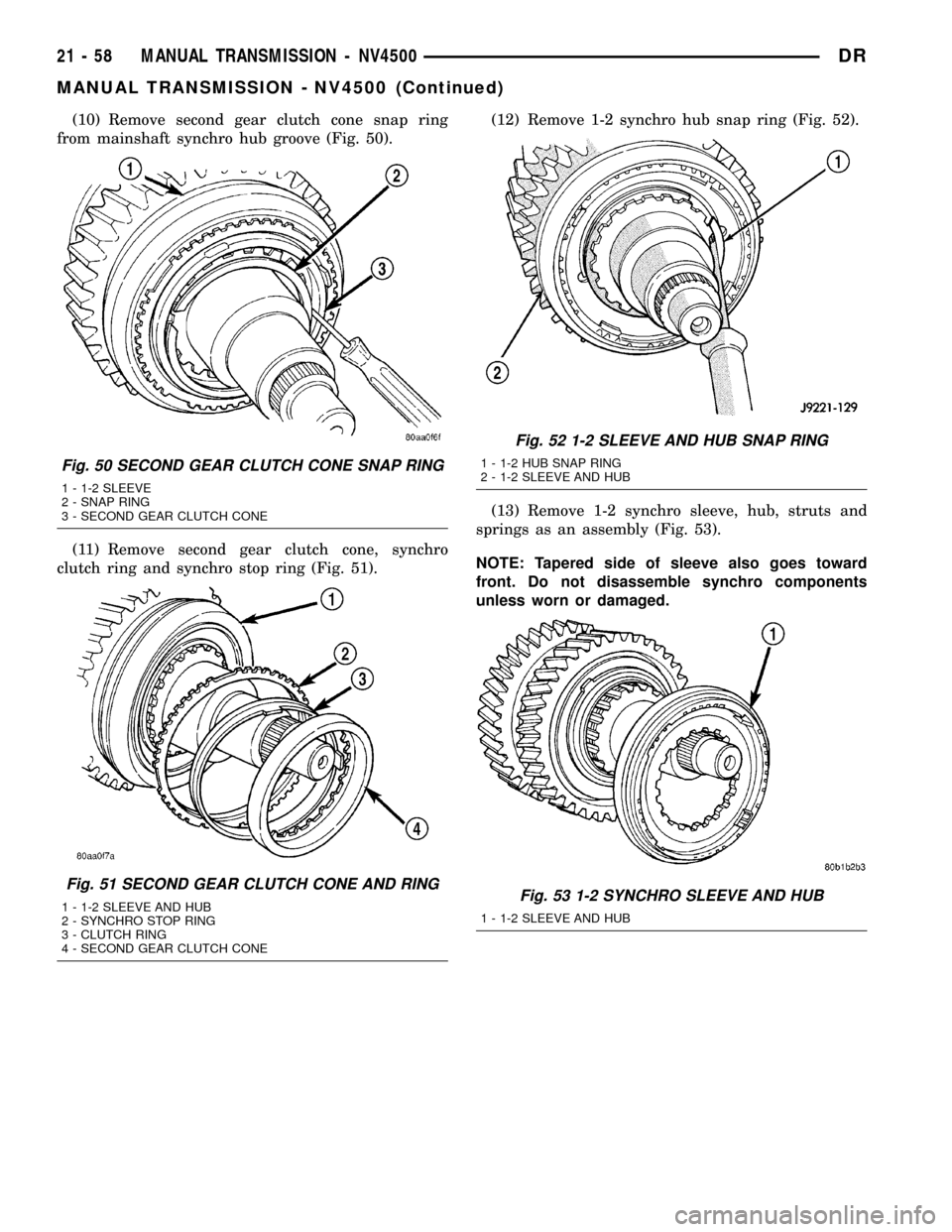
(10) Remove second gear clutch cone snap ring
from mainshaft synchro hub groove (Fig. 50).
(11) Remove second gear clutch cone, synchro
clutch ring and synchro stop ring (Fig. 51).(12) Remove 1-2 synchro hub snap ring (Fig. 52).
(13) Remove 1-2 synchro sleeve, hub, struts and
springs as an assembly (Fig. 53).
NOTE: Tapered side of sleeve also goes toward
front. Do not disassemble synchro components
unless worn or damaged.
Fig. 50 SECOND GEAR CLUTCH CONE SNAP RING
1 - 1-2 SLEEVE
2 - SNAP RING
3 - SECOND GEAR CLUTCH CONE
Fig. 51 SECOND GEAR CLUTCH CONE AND RING
1 - 1-2 SLEEVE AND HUB
2 - SYNCHRO STOP RING
3 - CLUTCH RING
4 - SECOND GEAR CLUTCH CONE
Fig. 52 1-2 SLEEVE AND HUB SNAP RING
1 - 1-2 HUB SNAP RING
2 - 1-2 SLEEVE AND HUB
Fig. 53 1-2 SYNCHRO SLEEVE AND HUB
1 - 1-2 SLEEVE AND HUB
21 - 58 MANUAL TRANSMISSION - NV4500DR
MANUAL TRANSMISSION - NV4500 (Continued)
Page 1764 of 2627
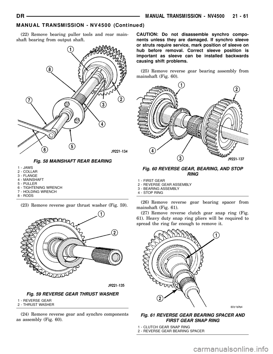
(22) Remove bearing puller tools and rear main-
shaft bearing from output shaft.
(23) Remove reverse gear thrust washer (Fig. 59).
(24) Remove reverse gear and synchro components
as assembly (Fig. 60).CAUTION: Do not disassemble synchro compo-
nents unless they are damaged. If synchro sleeve
or struts require service, mark position of sleeve on
hub before removal. Correct sleeve position is
important as sleeve can be installed backwards
causing shift problems.
(25) Remove reverse gear bearing assembly from
mainshaft (Fig. 60).
(26) Remove reverse gear bearing spacer from
mainshaft (Fig. 61).
(27) Remove reverse clutch gear snap ring (Fig.
61). Heavy duty snap ring pliers will be required to
spread the ring far enough to remove it.
Fig. 58 MAINSHAFT REAR BEARING
1-JAWS
2 - COLLAR
3 - FLANGE
4 - MAINSHAFT
5 - PULLER
6 - TIGHTENING WRENCH
7 - HOLDING WRENCH
8 - RODS
Fig. 59 REVERSE GEAR THRUST WASHER
1 - REVERSE GEAR
2 - THRUST WASHER
Fig. 60 REVERSE GEAR, BEARING, AND STOP
RING
1 - FIRST GEAR
2 - REVERSE GEAR ASSEMBLY
3 - BEARING ASSEMBLY
4 - STOP RING
Fig. 61 REVERSE GEAR BEARING SPACER AND
FIRST GEAR SNAP RING
1 - CLUTCH GEAR SNAP RING
2 - REVERSE GEAR BEARING SPACER
DRMANUAL TRANSMISSION - NV4500 21 - 61
MANUAL TRANSMISSION - NV4500 (Continued)
Page 1770 of 2627
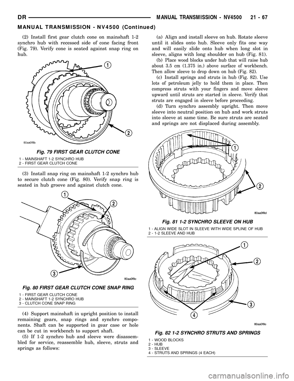
(2) Install first gear clutch cone on mainshaft 1-2
synchro hub with recessed side of cone facing front
(Fig. 79). Verify cone is seated against snap ring on
hub.
(3) Install snap ring on mainshaft 1-2 synchro hub
to secure clutch cone (Fig. 80). Verify snap ring is
seated in hub groove and against clutch cone.
(4) Support mainshaft in upright position to install
remaining gears, snap rings and synchro compo-
nents. Shaft can be supported in gear case or hole
can be cut in workbench to support shaft.
(5) If 1-2 synchro hub and sleeve were disassem-
bled for service, reassemble hub, sleeve, struts and
springs as follows:(a) Align and install sleeve on hub. Rotate sleeve
until it slides onto hub. Sleeve only fits one way
and will easily slide onto hub when long slot in
sleeve, aligns with long shoulder on hub (Fig. 81).
(b)
Place wood blocks under hub that will raise hub
about 3.5 cm (1.375 in.) above surface of workbench.
Then allow sleeve to drop down on hub (Fig. 82).
(c)Install springs and struts in hub (Fig. 82). Use
lots of petroleum jelly to hold them in place. Then
compress struts with your fingers and move sleeve
upward until struts are started in sleeve. Verify that
struts are engaged in sleeve before proceeding.
(d) Turn synchro assembly upright. Then move
sleeve into neutral position on hub and work struts
into sleeve at same time. Be sure struts are seated
and springs are not displaced during assembly.
Fig. 79 FIRST GEAR CLUTCH CONE
1 - MAINSHAFT 1-2 SYNCHRO HUB
2 - FIRST GEAR CLUTCH CONE
Fig. 80 FIRST GEAR CLUTCH CONE SNAP RING
1 - FIRST GEAR CLUTCH CONE
2 - MAINSHAFT 1-2 SYNCHRO HUB
3 - CLUTCH CONE SNAP RING
Fig. 81 1-2 SYNCHRO SLEEVE ON HUB
1 - ALIGN WIDE SLOT IN SLEEVE WITH WIDE SPLINE OF HUB
2 - 1-2 SLEEVE AND HUB
Fig. 82 1-2 SYNCHRO STRUTS AND SPRINGS
1 - WOOD BLOCKS
2 - HUB
3 - SLEEVE
4 - STRUTS AND SPRINGS (4 EACH)
DRMANUAL TRANSMISSION - NV4500 21 - 67
MANUAL TRANSMISSION - NV4500 (Continued)
Page 1774 of 2627
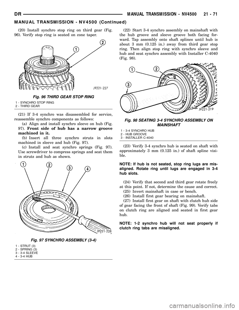
(20) Install synchro stop ring on third gear (Fig.
96). Verify stop ring is seated on cone taper.
(21) If 3-4 synchro was disassembled for service,
reassemble synchro components as follows:
(a) Align and install synchro sleeve on hub (Fig.
97).Front side of hub has a narrow groove
machined in it.
(b) Insert all three synchro struts in slots
machined in sleeve and hub (Fig. 97).
(c) Install and seat synchro springs (Fig. 97).
Use screwdriver to compress springs and seat them
in struts and hub as shown.(22) Start 3-4 synchro assembly on mainshaft with
the hub groove and sleeve groove both facing for-
ward. Tap assembly onto shaft splines until hub is
about 3 mm (0.125 in.) away from third gear stop
ring. Then align stop ring with synchro sleeve and
hub and seat synchro assembly with Installer C-4040
(Fig. 98).
(23) Verify 3-4 synchro hub is seated on shaft with
approximately 3 mm (0.125 in.) of shaft spline visi-
ble.
NOTE: If hub is not seated, stop ring lugs are mis-
aligned. Rotate ring until lugs are engaged in 3-4
hub slots.
(24) Verify that second and third gear rotate freely
at this point. If not, determine the cause and correct.
(25) Invert mainshaft in case or bench.
(26) Install first gear bearing on mainshaft.
(27) Install first gear on shaft with clutch hub side
of gear facing the front of shaft (Fig. 99). Verify tabs
on clutch ring are aligned and seated in first gear
hub.
NOTE: 1-2 synchro hub will not seat properly if
clutch ring tabs are misaligned.
Fig. 96 THIRD GEAR STOP RING
1 - SYNCHRO STOP RING
2 - THIRD GEAR
Fig. 97 SYNCHRO ASSEMBLY (3-4)
1 - STRUT (3)
2 - SPRING (3)
3 - 3-4 SLEEVE
4 - 3-4 HUB
Fig. 98 SEATING 3-4 SYNCHRO ASSEMBLY ON
MAINSHAFT
1 - 3-4 SYNCHRO HUB
2 - HUB GROOVE
3 - INSTALLER C-4040
DRMANUAL TRANSMISSION - NV4500 21 - 71
MANUAL TRANSMISSION - NV4500 (Continued)
Page 1775 of 2627
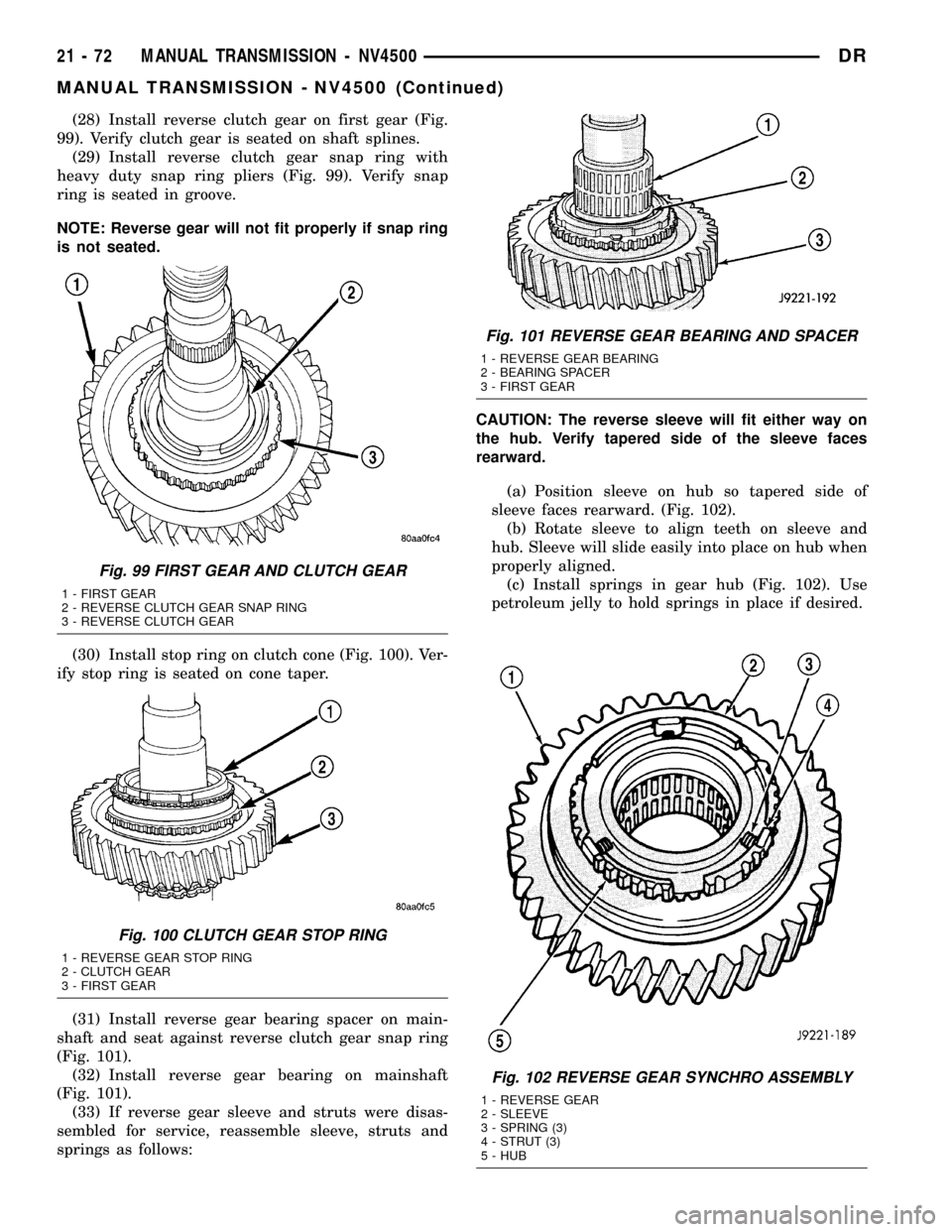
(28) Install reverse clutch gear on first gear (Fig.
99). Verify clutch gear is seated on shaft splines.
(29) Install reverse clutch gear snap ring with
heavy duty snap ring pliers (Fig. 99). Verify snap
ring is seated in groove.
NOTE: Reverse gear will not fit properly if snap ring
is not seated.
(30) Install stop ring on clutch cone (Fig. 100). Ver-
ify stop ring is seated on cone taper.
(31) Install reverse gear bearing spacer on main-
shaft and seat against reverse clutch gear snap ring
(Fig. 101).
(32) Install reverse gear bearing on mainshaft
(Fig. 101).
(33) If reverse gear sleeve and struts were disas-
sembled for service, reassemble sleeve, struts and
springs as follows:CAUTION: The reverse sleeve will fit either way on
the hub. Verify tapered side of the sleeve faces
rearward.
(a) Position sleeve on hub so tapered side of
sleeve faces rearward. (Fig. 102).
(b) Rotate sleeve to align teeth on sleeve and
hub. Sleeve will slide easily into place on hub when
properly aligned.
(c) Install springs in gear hub (Fig. 102). Use
petroleum jelly to hold springs in place if desired.
Fig. 102 REVERSE GEAR SYNCHRO ASSEMBLY
1 - REVERSE GEAR
2 - SLEEVE
3 - SPRING (3)
4 - STRUT (3)
5 - HUB
Fig. 99 FIRST GEAR AND CLUTCH GEAR
1 - FIRST GEAR
2 - REVERSE CLUTCH GEAR SNAP RING
3 - REVERSE CLUTCH GEAR
Fig. 100 CLUTCH GEAR STOP RING
1 - REVERSE GEAR STOP RING
2 - CLUTCH GEAR
3 - FIRST GEAR
Fig. 101 REVERSE GEAR BEARING AND SPACER
1 - REVERSE GEAR BEARING
2 - BEARING SPACER
3 - FIRST GEAR
21 - 72 MANUAL TRANSMISSION - NV4500DR
MANUAL TRANSMISSION - NV4500 (Continued)