1998 DODGE RAM 1500 Timing marks
[x] Cancel search: Timing marksPage 1303 of 2627
(8) Rotate the crankshaft two full revolutions, then
verify that the camshaft drive gear V6 marks are in
fact aligned.
(9) Install the cylinder head covers. Refer to Cylin-
der Head Cover in this section.
BALANCE SHAFT
REMOVAL
(1) Remove the primary and secondary timing
chains. Refer to TIMING CHAIN and SPROCKET.
NOTE: The balance shaft and gear are serviced as
an assembly. Do not attempt to remove the gear
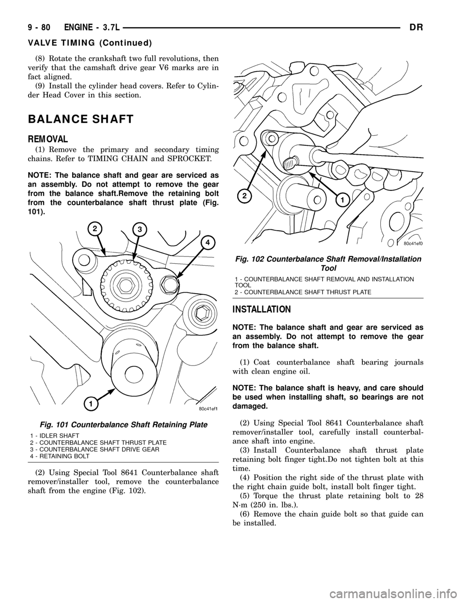
from the balance shaft.Remove the retaining bolt
from the counterbalance shaft thrust plate (Fig.
101).
(2) Using Special Tool 8641 Counterbalance shaft
remover/installer tool, remove the counterbalance
shaft from the engine (Fig. 102).
INSTALLATION
NOTE: The balance shaft and gear are serviced as
an assembly. Do not attempt to remove the gear
from the balance shaft.
(1) Coat counterbalance shaft bearing journals
with clean engine oil.
NOTE: The balance shaft is heavy, and care should
be used when installing shaft, so bearings are not
damaged.
(2) Using Special Tool 8641 Counterbalance shaft
remover/installer tool, carefully install counterbal-
ance shaft into engine.
(3) Install Counterbalance shaft thrust plate
retaining bolt finger tight.Do not tighten bolt at this
time.
(4) Position the right side of the thrust plate with
the right chain guide bolt, install bolt finger tight.
(5) Torque the thrust plate retaining bolt to 28
N´m (250 in. lbs.).
(6) Remove the chain guide bolt so that guide can
be installed.
Fig. 101 Counterbalance Shaft Retaining Plate
1 - IDLER SHAFT
2 - COUNTERBALANCE SHAFT THRUST PLATE
3 - COUNTERBALANCE SHAFT DRIVE GEAR
4 - RETAINING BOLT
Fig. 102 Counterbalance Shaft Removal/Installation
Tool
1 - COUNTERBALANCE SHAFT REMOVAL AND INSTALLATION
TOOL
2 - COUNTERBALANCE SHAFT THRUST PLATE
9 - 80 ENGINE - 3.7LDR
VALVE TIMING (Continued)
Page 1306 of 2627
TIMING BELT/CHAIN AND
SPROCKETS
REMOVAL
(1) Disconnect negative cable from battery.
(2) Drain cooling system(Refer to 7 - COOLING -
STANDARD PROCEDURE).
(3) Remove right and left cylinder head covers(Re-
fer to 9 - ENGINE/CYLINDER HEAD/CYLINDER
HEAD COVER(S) - REMOVAL).
(4) Remove radiator fan shroud(Refer to 7 - COOL-
ING/ENGINE/RADIATOR FAN - REMOVAL).
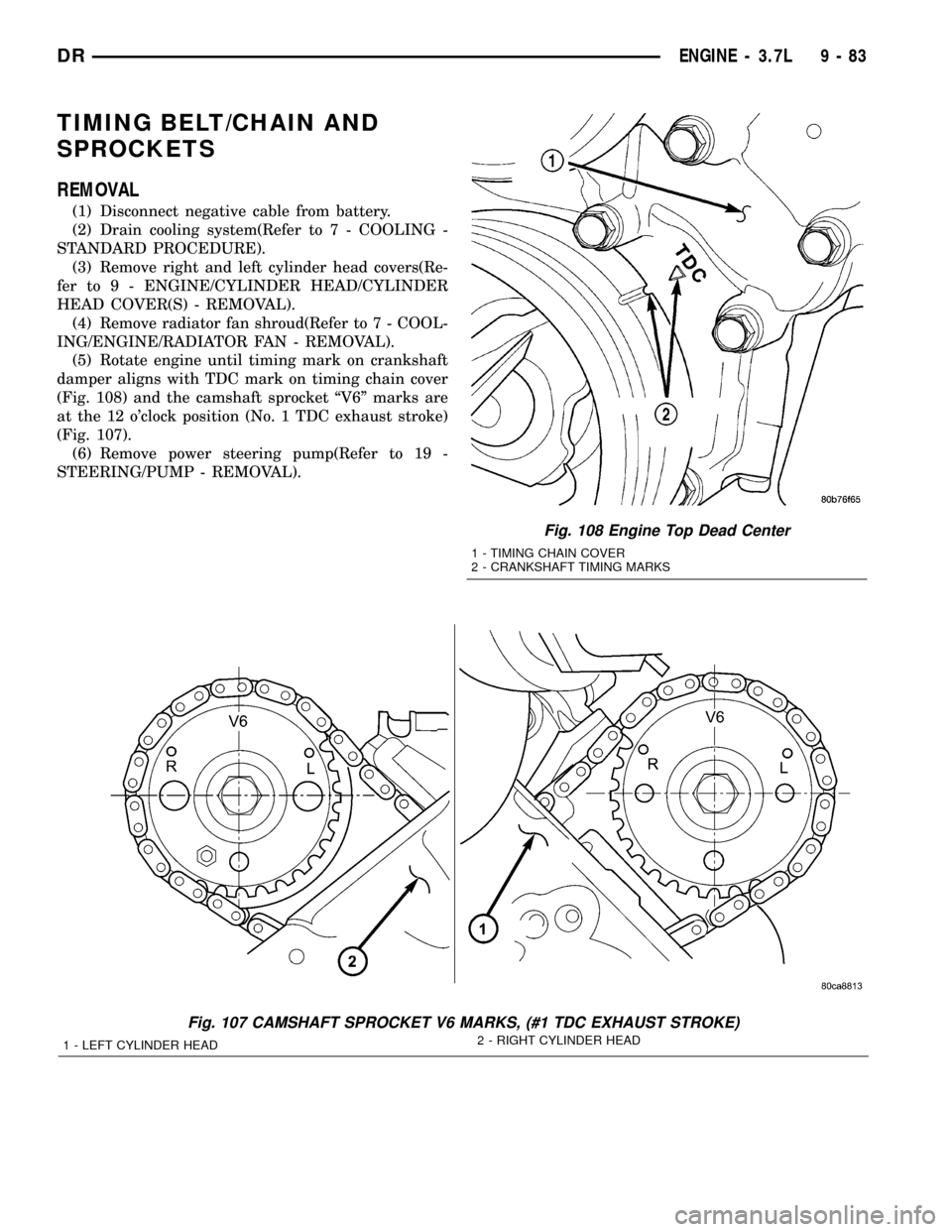
(5) Rotate engine until timing mark on crankshaft
damper aligns with TDC mark on timing chain cover
(Fig. 108) and the camshaft sprocket ªV6º marks are
at the 12 o'clock position (No. 1 TDC exhaust stroke)
(Fig. 107).
(6) Remove power steering pump(Refer to 19 -
STEERING/PUMP - REMOVAL).
Fig. 107 CAMSHAFT SPROCKET V6 MARKS, (#1 TDC EXHAUST STROKE)
1 - LEFT CYLINDER HEAD2 - RIGHT CYLINDER HEAD
Fig. 108 Engine Top Dead Center
1 - TIMING CHAIN COVER
2 - CRANKSHAFT TIMING MARKS
DRENGINE - 3.7L 9 - 83
Page 1309 of 2627
NOTE: It will be necessary to slightly rotate cam-
shafts for sprocket installation.
(11) Align left camshaft sprocket ªLº dot to plated
link on chain.
(12) Align right camshaft sprocket ªRº dot to
plated link on chain.
CAUTION: Remove excess oil from the camshaft
sprocket bolt. Failure to do so can result in over-
torque of bolt resulting in bolt failure.
(13) Remove Special Tool 8429, then attach both
sprockets to camshafts. Remove excess oil from bolts,
then Install sprocket bolts, but do not tighten at this
time.
(14) Verify that all plated links are aligned with
the marks on all sprockets and the ªV6º marks on
camshaft sprockets are at the 12 o'clock position.
CAUTION: Ensure the plate between the left sec-
ondary chain tensioner and block is correctly
installed.
(15) Install both secondary chain tensioners.
Tighten bolts to 28 N´m (250 in. lbs.).
NOTE: Left and right secondary chain tensioners
are not common.(16) Remove all locking pins (3) from tensioners.
CAUTION: After pulling locking pins out of each
tensioner, DO NOT manually extend the tensioner(s)
ratchet. Doing so will over tension the chains,
resulting in noise and/or high timing chain loads.
(17) Using Special Tool 6958, Spanner with Adap-
tor Pins 8346, tighten left (Fig. 114) and right (Fig.
115). camshaft sprocket bolts to 122 N´m (90 ft. lbs.).
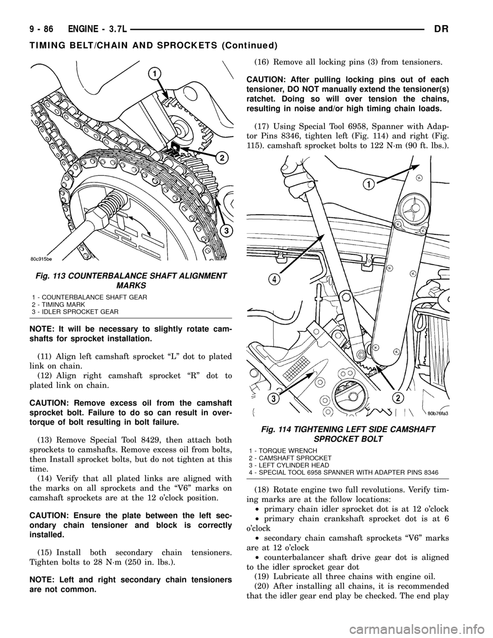
(18) Rotate engine two full revolutions. Verify tim-
ing marks are at the follow locations:
²primary chain idler sprocket dot is at 12 o'clock
²primary chain crankshaft sprocket dot is at 6
o'clock
²secondary chain camshaft sprockets ªV6º marks
are at 12 o'clock
²counterbalancer shaft drive gear dot is aligned
to the idler sprocket gear dot
(19) Lubricate all three chains with engine oil.
(20) After installing all chains, it is recommended
that the idler gear end play be checked. The end play
Fig. 113 COUNTERBALANCE SHAFT ALIGNMENT
MARKS
1 - COUNTERBALANCE SHAFT GEAR
2 - TIMING MARK
3 - IDLER SPROCKET GEAR
Fig. 114 TIGHTENING LEFT SIDE CAMSHAFT
SPROCKET BOLT
1 - TORQUE WRENCH
2 - CAMSHAFT SPROCKET
3 - LEFT CYLINDER HEAD
4 - SPECIAL TOOL 6958 SPANNER WITH ADAPTER PINS 8346
9 - 86 ENGINE - 3.7LDR
TIMING BELT/CHAIN AND SPROCKETS (Continued)
Page 1331 of 2627
REMOVAL
REMOVAL - LEFT CYLINDER HEAD
(1) Disconnect the negative cable from the battery.
(2) Raise the vehicle on a hoist.
(3) Disconnect the exhaust pipe at the left side
exhaust manifold.
(4) Drain the engine coolant. Refer to COOLING
SYSTEM.
(5) Lower the vehicle.
(6) Remove the intake manifold (Refer to 9 -
ENGINE/MANIFOLDS/INTAKE MANIFOLD -
REMOVAL).
(7) Remove the master cylinder and booster assem-
bly. Refer to section 5 brakes.
(8) Remove the cylinder head cover (Refer to 9 -
ENGINE/CYLINDER HEAD/CYLINDER HEAD
COVER(S) - REMOVAL).
(9) Remove the fan shroud and fan blade assembly
(Refer to 7 - COOLING/ENGINE/FAN DRIVE VIS-
COUS CLUTCH - REMOVAL).
(10) Remove accessory drive belt (Refer to 7 -
COOLING/ACCESSORY DRIVE/DRIVE BELTS -
REMOVAL).
(11) Remove the power steering pump and set
aside.
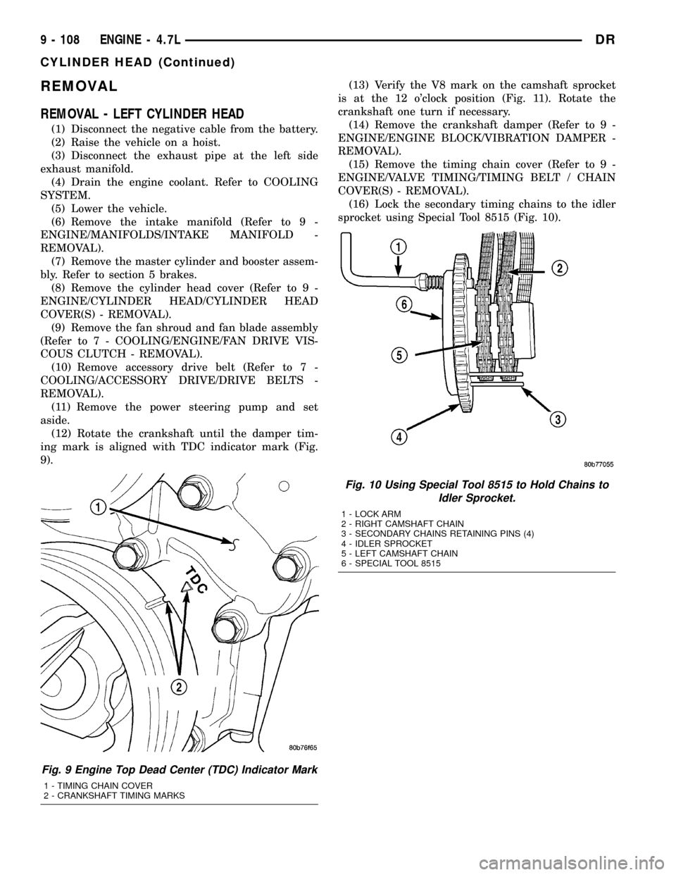
(12) Rotate the crankshaft until the damper tim-
ing mark is aligned with TDC indicator mark (Fig.
9).(13) Verify the V8 mark on the camshaft sprocket
is at the 12 o'clock position (Fig. 11). Rotate the
crankshaft one turn if necessary.
(14) Remove the crankshaft damper (Refer to 9 -
ENGINE/ENGINE BLOCK/VIBRATION DAMPER -
REMOVAL).
(15) Remove the timing chain cover (Refer to 9 -
ENGINE/VALVE TIMING/TIMING BELT / CHAIN
COVER(S) - REMOVAL).
(16) Lock the secondary timing chains to the idler
sprocket using Special Tool 8515 (Fig. 10).
Fig. 9 Engine Top Dead Center (TDC) Indicator Mark
1 - TIMING CHAIN COVER
2 - CRANKSHAFT TIMING MARKS
Fig. 10 Using Special Tool 8515 to Hold Chains to
Idler Sprocket.
1 - LOCK ARM
2 - RIGHT CAMSHAFT CHAIN
3 - SECONDARY CHAINS RETAINING PINS (4)
4 - IDLER SPROCKET
5 - LEFT CAMSHAFT CHAIN
6 - SPECIAL TOOL 8515
9 - 108 ENGINE - 4.7LDR
CYLINDER HEAD (Continued)
Page 1332 of 2627
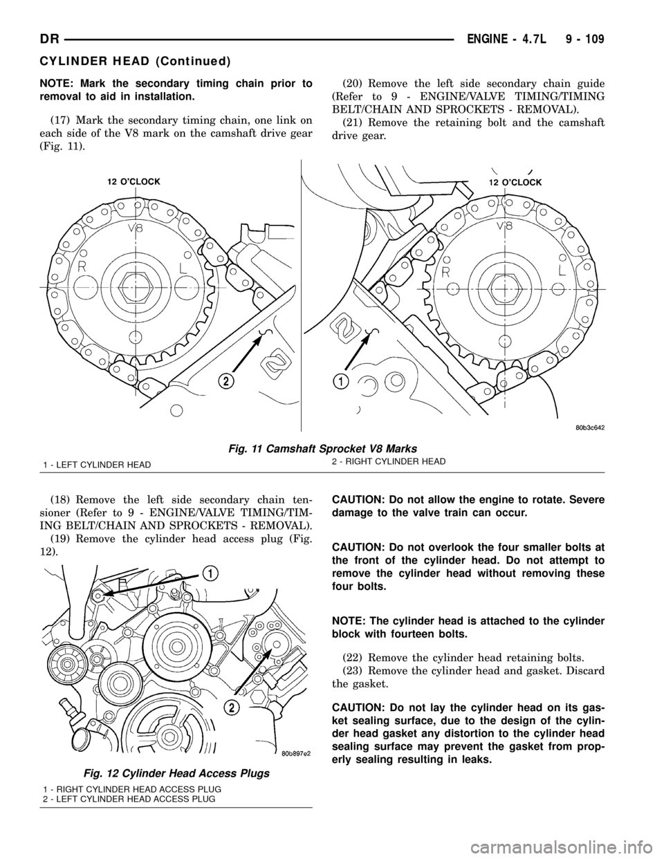
NOTE: Mark the secondary timing chain prior to
removal to aid in installation.
(17) Mark the secondary timing chain, one link on
each side of the V8 mark on the camshaft drive gear
(Fig. 11).
(18) Remove the left side secondary chain ten-
sioner (Refer to 9 - ENGINE/VALVE TIMING/TIM-
ING BELT/CHAIN AND SPROCKETS - REMOVAL).
(19) Remove the cylinder head access plug (Fig.
12).(20) Remove the left side secondary chain guide
(Refer to 9 - ENGINE/VALVE TIMING/TIMING
BELT/CHAIN AND SPROCKETS - REMOVAL).
(21) Remove the retaining bolt and the camshaft
drive gear.
CAUTION: Do not allow the engine to rotate. Severe
damage to the valve train can occur.
CAUTION: Do not overlook the four smaller bolts at
the front of the cylinder head. Do not attempt to
remove the cylinder head without removing these
four bolts.
NOTE: The cylinder head is attached to the cylinder
block with fourteen bolts.
(22) Remove the cylinder head retaining bolts.
(23) Remove the cylinder head and gasket. Discard
the gasket.
CAUTION: Do not lay the cylinder head on its gas-
ket sealing surface, due to the design of the cylin-
der head gasket any distortion to the cylinder head
sealing surface may prevent the gasket from prop-
erly sealing resulting in leaks.
Fig. 11 Camshaft Sprocket V8 Marks
1 - LEFT CYLINDER HEAD2 - RIGHT CYLINDER HEAD
Fig. 12 Cylinder Head Access Plugs
1 - RIGHT CYLINDER HEAD ACCESS PLUG
2 - LEFT CYLINDER HEAD ACCESS PLUG
DRENGINE - 4.7L 9 - 109
CYLINDER HEAD (Continued)
Page 1333 of 2627
REMOVAL - RIGHT CYLINDER HEAD
(1) Disconnect battery negitive cable.
(2) Raise the vehicle on a hoist.
(3) Disconnect the exhaust pipe at the right side
exhaust manifold.
(4) Drain the engine coolant (Refer to 7 - COOL-
ING - STANDARD PROCEDURE).
(5) Lower the vehicle.
(6) Remove the intake manifold (Refer to 9 -
ENGINE/MANIFOLDS/INTAKE MANIFOLD -
REMOVAL).
(7) Remove the cylinder head cover (Refer to 9 -
ENGINE/CYLINDER HEAD/CYLINDER HEAD
COVER(S) - REMOVAL).
(8) Remove the fan shroud (Refer to 7 - COOLING/
ENGINE/FAN DRIVE VISCOUS CLUTCH -
REMOVAL).
(9) Remove oil fill housing from cylinder head.
(10) Remove accessory drive belt (Refer to 7 -
COOLING/ACCESSORY DRIVE/DRIVE BELTS -
REMOVAL).
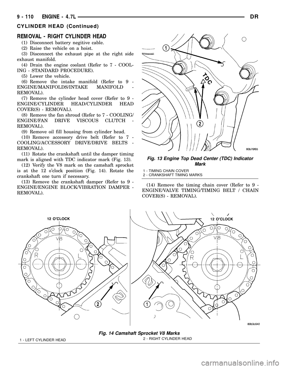
(11) Rotate the crankshaft until the damper timing
mark is aligned with TDC indicator mark (Fig. 13).
(12) Verify the V8 mark on the camshaft sprocket
is at the 12 o'clock position (Fig. 14). Rotate the
crankshaft one turn if necessary.
(13) Remove the crankshaft damper (Refer to 9 -
ENGINE/ENGINE BLOCK/VIBRATION DAMPER -
REMOVAL).(14) Remove the timing chain cover (Refer to 9 -
ENGINE/VALVE TIMING/TIMING BELT / CHAIN
COVER(S) - REMOVAL).
Fig. 13 Engine Top Dead Center (TDC) Indicator
Mark
1 - TIMING CHAIN COVER
2 - CRANKSHAFT TIMING MARKS
Fig. 14 Camshaft Sprocket V8 Marks
1 - LEFT CYLINDER HEAD2 - RIGHT CYLINDER HEAD
9 - 110 ENGINE - 4.7LDR
CYLINDER HEAD (Continued)
Page 1338 of 2627
the camshaft, four on the steel tube and one on the
steel nose piece. Camshaft end play is controlled by
two thrust walls that border the nose piece journal.
Engine oil enters the hollow camshafts at the third
journal and lubricates every intake lobe rocker
through a drilled passage in the intake lobe.
REMOVAL
CAUTION: When the timing chain is removed and
the cylinder heads are still installed, DO NOT force-
fully rotate the camshafts or crankshaft indepen-
dently of each other. Severe valve and/or piston
damage can occur.
CAUTION: When removing the cam sprocket, timing
chains or camshaft, Failure to use Special Tool
8350 will result in hydraulic tensioner ratchet over
extension, requiring timing chain cover removal to
reset the tensioner ratchet.
(1) Remove cylinder head cover (Refer to 9 -
ENGINE/CYLINDER HEAD/CYLINDER HEAD
COVER(S) - REMOVAL).
(2) Set engine to TDC cylinder #1, camshaft
sprocket V8 marks at the 12 o'clock position.
(3) Mark one link on the secondary timing chain
on both sides of the V8 mark on the camshaft
sprocket to aid in installation.CAUTION: Do not hold or pry on the camshaft tar-
get wheel (Located on the right side camshaft
sprocket) for any reason, Severe damage will occur
to the target wheel resulting in a vehicle no start
condition.
(4) Loosen butDO NOTremove the camshaft
sprocket retaining bolt. Leave the bolt snug against
the sprocket.
NOTE: The timing chain tensioners must be
secured prior to removing the camshaft sprockets.
Failure to secure tensioners will allow the tension-
ers to extend, requiring timing chain cover removal
in order to reset tensioners.
CAUTION: Do not force wedge past the narrowest
point between the chain strands. Damage to the
tensioners may occur.
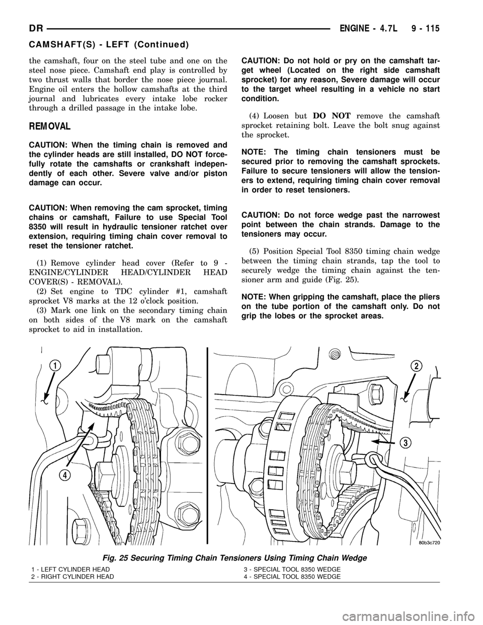
(5) Position Special Tool 8350 timing chain wedge
between the timing chain strands, tap the tool to
securely wedge the timing chain against the ten-
sioner arm and guide (Fig. 25).
NOTE: When gripping the camshaft, place the pliers
on the tube portion of the camshaft only. Do not
grip the lobes or the sprocket areas.
Fig. 25 Securing Timing Chain Tensioners Using Timing Chain Wedge
1 - LEFT CYLINDER HEAD
2 - RIGHT CYLINDER HEAD3 - SPECIAL TOOL 8350 WEDGE
4 - SPECIAL TOOL 8350 WEDGE
DRENGINE - 4.7L 9 - 115
CAMSHAFT(S) - LEFT (Continued)
Page 1342 of 2627
CAMSHAFT(S) - RIGHT
DESCRIPTION
The camshafts consist of powdered metal steel lobes
which are sinter-bonded to a steel tube. A steel post or
nose piece is friction-welded to the steel camshaft tube.
Five bearing journals are machined into the camshaft,
four on the steel tube and one on the steel nose piece.
Camshaft end play is controlled by two thrust walls
that border the nose piece journal. Engine oil enters the
hollow camshafts at the third journal and lubricates
every intake lobe rocker through a drilled passage in
the intake lobe.
REMOVAL
CAUTION: When the timing chain is removed and
the cylinder heads are still installed, DO NOT force-
fully rotate the camshafts or crankshaft indepen-
dently of each other. Severe valve and/or piston
damage can occur.
CAUTION: When removing the cam sprocket, timing
chains or camshaft, Failure to use special tool 8350
will result in hydraulic tensioner ratchet over exten-
sion, Requiring timing chain cover removal to re-set
the tensioner ratchet.(1) Remove the cylinder head covers (Refer to 9 -
ENGINE/CYLINDER HEAD/CYLINDER HEAD
COVER(S) - REMOVAL).
(2) Set engine to TDC cylinder #1, camshaft
sprocket V8 marks at the 12 o'clock position.
(3) Mark one link on the secondary timing chain
on both sides of the V8 mark on the camshaft
sprocket to aid in installation.
CAUTION: Do not hold or pry on the camshaft tar-
get wheel for any reason, Severe damage will occur
to the target wheel. A damaged target wheel could
cause a vehicle no start condition.
(4)
Loosen butDO NOTremove the camshaft
sprocket retaining bolt. Leave bolt snug against sprocket.
NOTE: The timing chain tensioners must be
secured prior to removing the camshaft sprockets.
Failure to secure tensioners will allow the tension-
ers to extend, requiring timing chain cover removal
in order to reset tensioners.
CAUTION: Do not force wedge past the narrowest
point between the chain strands. Damage to the
tensioners may occur.
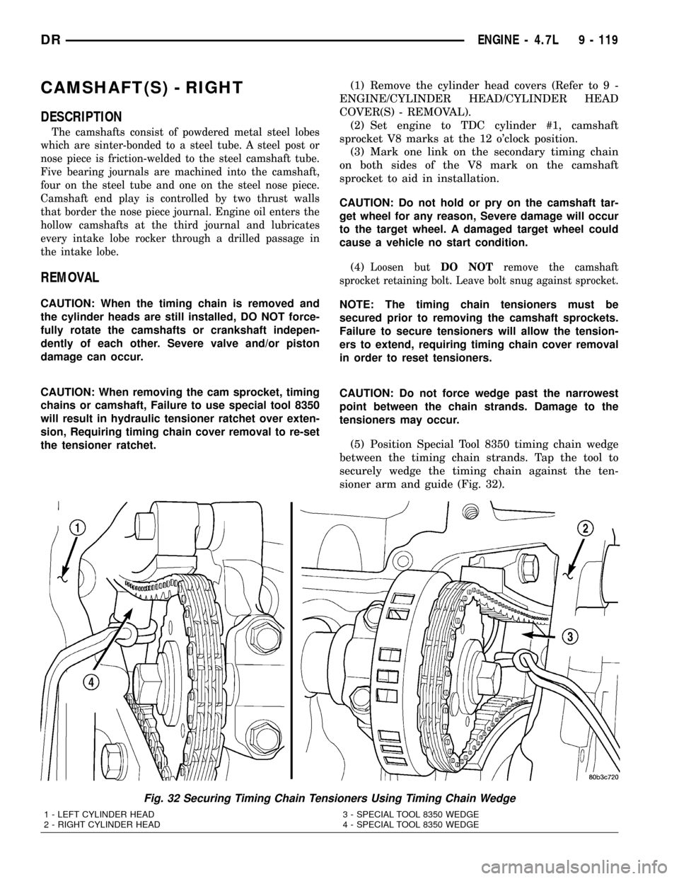
(5) Position Special Tool 8350 timing chain wedge
between the timing chain strands. Tap the tool to
securely wedge the timing chain against the ten-
sioner arm and guide (Fig. 32).
Fig. 32 Securing Timing Chain Tensioners Using Timing Chain Wedge
1 - LEFT CYLINDER HEAD
2 - RIGHT CYLINDER HEAD3 - SPECIAL TOOL 8350 WEDGE
4 - SPECIAL TOOL 8350 WEDGE
DRENGINE - 4.7L 9 - 119