1998 DODGE RAM 1500 Flywheel bolts
[x] Cancel search: Flywheel boltsPage 1418 of 2627
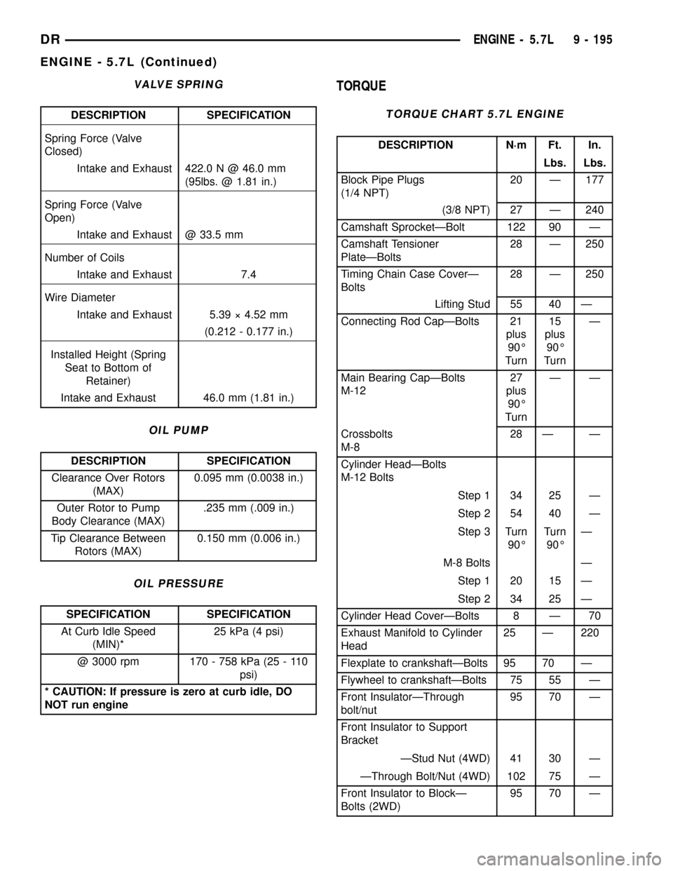
VALVE SPRING
DESCRIPTION SPECIFICATION
Spring Force (Valve
Closed)
Intake and Exhaust 422.0 N @ 46.0 mm
(95lbs. @ 1.81 in.)
Spring Force (Valve
Open)
Intake and Exhaust @ 33.5 mm
Number of Coils
Intake and Exhaust 7.4
Wire Diameter
Intake and Exhaust 5.39 ý 4.52 mm
(0.212 - 0.177 in.)
Installed Height (Spring
Seat to Bottom of
Retainer)
Intake and Exhaust 46.0 mm (1.81 in.)
OIL PUMP
DESCRIPTION SPECIFICATION
Clearance Over Rotors
(MAX)0.095 mm (0.0038 in.)
Outer Rotor to Pump
Body Clearance (MAX).235 mm (.009 in.)
Tip Clearance Between
Rotors (MAX)0.150 mm (0.006 in.)
OIL PRESSURE
SPECIFICATION SPECIFICATION
At Curb Idle Speed
(MIN)*25 kPa (4 psi)
@ 3000 rpm 170 - 758 kPa (25 - 110
psi)
* CAUTION: If pressure is zero at curb idle, DO
NOT run engine
TORQUE
TORQUE CHART 5.7L ENGINE
DESCRIPTION N´m Ft. In.
Lbs. Lbs.
Block Pipe Plugs
(1/4 NPT)20 Ð 177
(3/8 NPT) 27 Ð 240
Camshaft SprocketÐBolt 122 90 Ð
Camshaft Tensioner
PlateÐBolts28 Ð 250
Timing Chain Case CoverÐ
Bolts28 Ð 250
Lifting Stud 55 40 Ð
Connecting Rod CapÐBolts 21
plus
90É
Turn15
plus
90É
TurnÐ
Main Bearing CapÐBolts
M-1227
plus
90É
TurnÐÐ
Crossbolts
M-828 Ð Ð
Cylinder HeadÐBolts
M-12 Bolts
Step 1 34 25 Ð
Step 2 54 40 Ð
Step 3 Turn
90ÉTurn
90ÉÐ
M-8 Bolts Ð
Step 1 20 15 Ð
Step 2 34 25 Ð
Cylinder Head CoverÐBolts 8 Ð 70
Exhaust Manifold to Cylinder
Head25 Ð 220
Flexplate to crankshaftÐBolts 95 70 Ð
Flywheel to crankshaftÐBolts 75 55 Ð
Front InsulatorÐThrough
bolt/nut95 70 Ð
Front Insulator to Support
Bracket
ÐStud Nut (4WD) 41 30 Ð
ÐThrough Bolt/Nut (4WD) 102 75 Ð
Front Insulator to BlockÐ
Bolts (2WD)95 70 Ð
DRENGINE - 5.7L 9 - 195
ENGINE - 5.7L (Continued)
Page 1432 of 2627
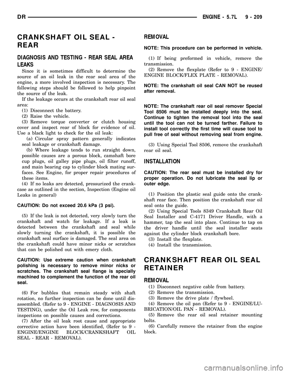
CRANKSHAFT OIL SEAL -
REAR
DIAGNOSIS AND TESTING - REAR SEAL AREA
LEAKS
Since it is sometimes difficult to determine the
source of an oil leak in the rear seal area of the
engine, a more involved inspection is necessary. The
following steps should be followed to help pinpoint
the source of the leak.
If the leakage occurs at the crankshaft rear oil seal
area:
(1) Disconnect the battery.
(2) Raise the vehicle.
(3) Remove torque converter or clutch housing
cover and inspect rear of block for evidence of oil.
Use a black light to check for the oil leak:
(a) Circular spray pattern generally indicates
seal leakage or crankshaft damage.
(b) Where leakage tends to run straight down,
possible causes are a porous block, camshaft bore
cup plugs, oil galley pipe plugs, oil filter runoff,
and main bearing cap to cylinder block mating sur-
faces. See Engine, for proper repair procedures of
these items.
(4) If no leaks are detected, pressurized the crank-
case as outlined in the section, Inspection (Engine oil
Leaks in general)
CAUTION: Do not exceed 20.6 kPa (3 psi).
(5) If the leak is not detected, very slowly turn the
crankshaft and watch for leakage. If a leak is
detected between the crankshaft and seal while
slowly turning the crankshaft, it is possible the
crankshaft seal surface is damaged. The seal area on
the crankshaft could have minor nicks or scratches
that can be polished out with emery cloth.
CAUTION: Use extreme caution when crankshaft
polishing is necessary to remove minor nicks or
scratches. The crankshaft seal flange is specially
machined to complement the function of the rear oil
seal.
(6) For bubbles that remain steady with shaft
rotation, no further inspection can be done until dis-
assembled. (Refer to 9 - ENGINE - DIAGNOSIS AND
TESTING), under the Oil Leak row, for components
inspections on possible causes and corrections.
(7) After the oil leak root cause and appropriate
corrective action have been identified, (Refer to 9 -
ENGINE/ENGINE BLOCK/CRANKSHAFT OIL
SEAL - REAR - REMOVAL).
REMOVAL
NOTE: This procedure can be performed in vehicle.
(1) If being preformed in vehicle, remove the
transmission.
(2) Remove the flexplate (Refer to 9 - ENGINE/
ENGINE BLOCK/FLEX PLATE - REMOVAL).
NOTE: The crankshaft oil seal CAN NOT be reused
after removal.
NOTE: The crankshaft rear oil seal remover Special
Tool 8506 must be installed deeply into the seal.
Continue to tighten the removal tool into the seal
until the tool can not be turned farther. Failure to
install tool correctly the first time will cause tool to
pull free of seal without removing seal from engine.
(3) Using Special Tool 8506, remove the crankshaft
rear oil seal.
INSTALLATION
CAUTION: The rear seal must be installed dry for
proper operation. Do not lubricate the seal lip or
outer edge.
(1) Position the plastic seal guide onto the crank-
shaft rear face. Then position the crankshaft rear oil
seal onto the guide.
(2) Using Special Tools 8349 Crankshaft Rear Oil
Seal Installer and C-4171 Driver Handle, with a
hammer, tap the seal into place. Continue to tap on
the driver handle until the seal installer seats
against the cylinder block crankshaft bore.
(3) Install the flexplate.
(4) Install the transmission.
CRANKSHAFT REAR OIL SEAL
RETAINER
REMOVAL
(1) Disconnect negative cable from battery.
(2) Remove the transmission.
(3) Remove the drive plate / flywheel.
(4) Remove the oil pan (Refer to 9 - ENGINE/LU-
BRICATION/OIL PAN - REMOVAL).
(5) Remove the rear oil seal retainer mounting
bolts.
(6) Carefully remove the retainer from the engine
block.
DRENGINE - 5.7L 9 - 209
Page 1433 of 2627
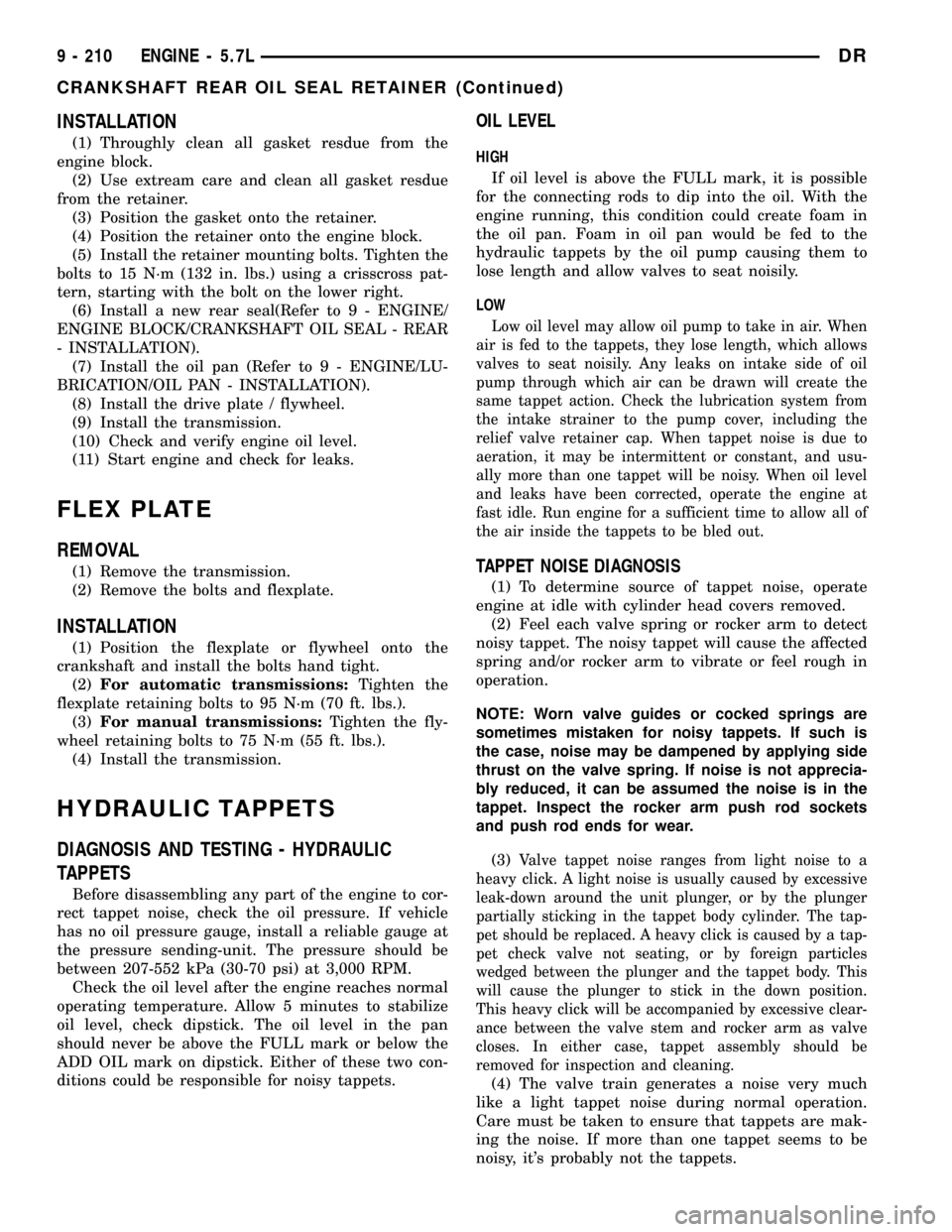
INSTALLATION
(1) Throughly clean all gasket resdue from the
engine block.
(2) Use extream care and clean all gasket resdue
from the retainer.
(3) Position the gasket onto the retainer.
(4) Position the retainer onto the engine block.
(5) Install the retainer mounting bolts. Tighten the
bolts to 15 N´m (132 in. lbs.) using a crisscross pat-
tern, starting with the bolt on the lower right.
(6) Install a new rear seal(Refer to 9 - ENGINE/
ENGINE BLOCK/CRANKSHAFT OIL SEAL - REAR
- INSTALLATION).
(7) Install the oil pan (Refer to 9 - ENGINE/LU-
BRICATION/OIL PAN - INSTALLATION).
(8) Install the drive plate / flywheel.
(9) Install the transmission.
(10) Check and verify engine oil level.
(11) Start engine and check for leaks.
FLEX PLATE
REMOVAL
(1) Remove the transmission.
(2) Remove the bolts and flexplate.
INSTALLATION
(1) Position the flexplate or flywheel onto the
crankshaft and install the bolts hand tight.
(2)For automatic transmissions:Tighten the
flexplate retaining bolts to 95 N´m (70 ft. lbs.).
(3)For manual transmissions:Tighten the fly-
wheel retaining bolts to 75 N´m (55 ft. lbs.).
(4) Install the transmission.
HYDRAULIC TAPPETS
DIAGNOSIS AND TESTING - HYDRAULIC
TAPPETS
Before disassembling any part of the engine to cor-
rect tappet noise, check the oil pressure. If vehicle
has no oil pressure gauge, install a reliable gauge at
the pressure sending-unit. The pressure should be
between 207-552 kPa (30-70 psi) at 3,000 RPM.
Check the oil level after the engine reaches normal
operating temperature. Allow 5 minutes to stabilize
oil level, check dipstick. The oil level in the pan
should never be above the FULL mark or below the
ADD OIL mark on dipstick. Either of these two con-
ditions could be responsible for noisy tappets.
OIL LEVEL
HIGH
If oil level is above the FULL mark, it is possible
for the connecting rods to dip into the oil. With the
engine running, this condition could create foam in
the oil pan. Foam in oil pan would be fed to the
hydraulic tappets by the oil pump causing them to
lose length and allow valves to seat noisily.
LOW
Low oil level may allow oil pump to take in air. When
air is fed to the tappets, they lose length, which allows
valves to seat noisily. Any leaks on intake side of oil
pump through which air can be drawn will create the
same tappet action. Check the lubrication system from
the intake strainer to the pump cover, including the
relief valve retainer cap. When tappet noise is due to
aeration, it may be intermittent or constant, and usu-
ally more than one tappet will be noisy. When oil level
and leaks have been corrected, operate the engine at
fast idle. Run engine for a sufficient time to allow all of
the air inside the tappets to be bled out.
TAPPET NOISE DIAGNOSIS
(1) To determine source of tappet noise, operate
engine at idle with cylinder head covers removed.
(2) Feel each valve spring or rocker arm to detect
noisy tappet. The noisy tappet will cause the affected
spring and/or rocker arm to vibrate or feel rough in
operation.
NOTE: Worn valve guides or cocked springs are
sometimes mistaken for noisy tappets. If such is
the case, noise may be dampened by applying side
thrust on the valve spring. If noise is not apprecia-
bly reduced, it can be assumed the noise is in the
tappet. Inspect the rocker arm push rod sockets
and push rod ends for wear.
(3)
Valve tappet noise ranges from light noise to a
heavy click. A light noise is usually caused by excessive
leak-down around the unit plunger, or by the plunger
partially sticking in the tappet body cylinder. The tap-
pet should be replaced. A heavy click is caused by a tap-
pet check valve not seating, or by foreign particles
wedged between the plunger and the tappet body. This
will cause the plunger to stick in the down position.
This heavy click will be accompanied by excessive clear-
ance between the valve stem and rocker arm as valve
closes. In either case, tappet assembly should be
removed for inspection and cleaning.
(4) The valve train generates a noise very much
like a light tappet noise during normal operation.
Care must be taken to ensure that tappets are mak-
ing the noise. If more than one tappet seems to be
noisy, it's probably not the tappets.
9 - 210 ENGINE - 5.7LDR
CRANKSHAFT REAR OIL SEAL RETAINER (Continued)
Page 1464 of 2627
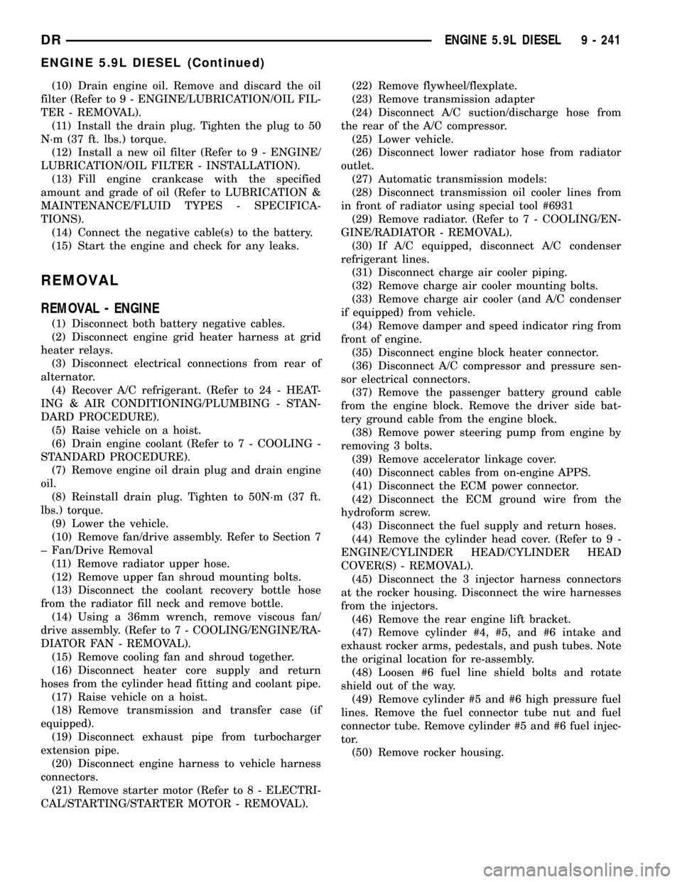
(10) Drain engine oil. Remove and discard the oil
filter (Refer to 9 - ENGINE/LUBRICATION/OIL FIL-
TER - REMOVAL).
(11) Install the drain plug. Tighten the plug to 50
N´m (37 ft. lbs.) torque.
(12) Install a new oil filter (Refer to 9 - ENGINE/
LUBRICATION/OIL FILTER - INSTALLATION).
(13) Fill engine crankcase with the specified
amount and grade of oil (Refer to LUBRICATION &
MAINTENANCE/FLUID TYPES - SPECIFICA-
TIONS).
(14) Connect the negative cable(s) to the battery.
(15) Start the engine and check for any leaks.
REMOVAL
REMOVAL - ENGINE
(1) Disconnect both battery negative cables.
(2) Disconnect engine grid heater harness at grid
heater relays.
(3) Disconnect electrical connections from rear of
alternator.
(4) Recover A/C refrigerant. (Refer to 24 - HEAT-
ING & AIR CONDITIONING/PLUMBING - STAN-
DARD PROCEDURE).
(5) Raise vehicle on a hoist.
(6) Drain engine coolant (Refer to 7 - COOLING -
STANDARD PROCEDURE).
(7) Remove engine oil drain plug and drain engine
oil.
(8) Reinstall drain plug. Tighten to 50N´m (37 ft.
lbs.) torque.
(9) Lower the vehicle.
(10) Remove fan/drive assembly. Refer to Section 7
± Fan/Drive Removal
(11) Remove radiator upper hose.
(12) Remove upper fan shroud mounting bolts.
(13) Disconnect the coolant recovery bottle hose
from the radiator fill neck and remove bottle.
(14) Using a 36mm wrench, remove viscous fan/
drive assembly. (Refer to 7 - COOLING/ENGINE/RA-
DIATOR FAN - REMOVAL).
(15) Remove cooling fan and shroud together.
(16) Disconnect heater core supply and return
hoses from the cylinder head fitting and coolant pipe.
(17) Raise vehicle on a hoist.
(18) Remove transmission and transfer case (if
equipped).
(19) Disconnect exhaust pipe from turbocharger
extension pipe.
(20) Disconnect engine harness to vehicle harness
connectors.
(21) Remove starter motor (Refer to 8 - ELECTRI-
CAL/STARTING/STARTER MOTOR - REMOVAL).(22) Remove flywheel/flexplate.
(23) Remove transmission adapter
(24) Disconnect A/C suction/discharge hose from
the rear of the A/C compressor.
(25) Lower vehicle.
(26) Disconnect lower radiator hose from radiator
outlet.
(27) Automatic transmission models:
(28) Disconnect transmission oil cooler lines from
in front of radiator using special tool #6931
(29) Remove radiator. (Refer to 7 - COOLING/EN-
GINE/RADIATOR - REMOVAL).
(30) If A/C equipped, disconnect A/C condenser
refrigerant lines.
(31) Disconnect charge air cooler piping.
(32) Remove charge air cooler mounting bolts.
(33) Remove charge air cooler (and A/C condenser
if equipped) from vehicle.
(34) Remove damper and speed indicator ring from
front of engine.
(35) Disconnect engine block heater connector.
(36) Disconnect A/C compressor and pressure sen-
sor electrical connectors.
(37) Remove the passenger battery ground cable
from the engine block. Remove the driver side bat-
tery ground cable from the engine block.
(38) Remove power steering pump from engine by
removing 3 bolts.
(39) Remove accelerator linkage cover.
(40) Disconnect cables from on-engine APPS.
(41) Disconnect the ECM power connector.
(42) Disconnect the ECM ground wire from the
hydroform screw.
(43) Disconnect the fuel supply and return hoses.
(44) Remove the cylinder head cover. (Refer to 9 -
ENGINE/CYLINDER HEAD/CYLINDER HEAD
COVER(S) - REMOVAL).
(45) Disconnect the 3 injector harness connectors
at the rocker housing. Disconnect the wire harnesses
from the injectors.
(46) Remove the rear engine lift bracket.
(47) Remove cylinder #4, #5, and #6 intake and
exhaust rocker arms, pedestals, and push tubes. Note
the original location for re-assembly.
(48) Loosen #6 fuel line shield bolts and rotate
shield out of the way.
(49) Remove cylinder #5 and #6 high pressure fuel
lines. Remove the fuel connector tube nut and fuel
connector tube. Remove cylinder #5 and #6 fuel injec-
tor.
(50) Remove rocker housing.
DRENGINE 5.9L DIESEL 9 - 241
ENGINE 5.9L DIESEL (Continued)
Page 1466 of 2627
(8) Replace injector o-ring and sealing washer on
injectors #5 and #6. Install injectors and torque using
the following steps:
²Step 1ÐInstall injector hold-down capscrews
and torque to 5 N´m (44 in. lbs.) torque.
²Step 2ÐLoosen injector hold-down capscrews.
²Step 3ÐInstall HPC connector tube and nut.
Torque nut to 15 N´m (11 ft. lbs.) torque.
²Step 4ÐTorque injector hold-down capscrews to
10 N´m (89 in. lbs.) torque.
²Step 5ÐTorque HPC connector tube nut to 50
N´m (37 ft. lbs.) torque.
(9) Install #5 and #6 high pressure fuel lines. Fol-
low correct torque sequence per section 14. Torque
fuel line fittings to 30 N-m (22 ft-lb). Torque brace
capscrew to 24 N-m (18 ft-lb).
(10) Install rear engine lift bracket. Torque to 77
N-m (57 ft-lb).
(11) Install push tubes, rocker arms, and pedestals
for cylinders #4, #5, and #6. Torque the mounting
bolts to 36 N-m (27 ft-lbs).
(12) Reset valve lash on cylinders #4, #5, and #6.
Torque adjusting nuts to 24 N-m (18 ft-lbs).
(13) Install cylinder head cover. Torque to 24 N-m
(18 ft-lbs).(Refer to 9 - ENGINE/CYLINDER HEAD -
INSTALLATION).
(14) Connect breather tube and lube oil drain tube
to breather housing cover. Install breather housing.
Torque capscrews to 24 N-m (18 ft-lbs)
(15) Connect fuel supply and return hoses.
(16) Connect ECM ground to hydroform screw.
Connect ECM power connector.
(17) Install the APPS cable(s) to the APPS. Install
the throttle linkage cover.
(18) Install the power steering pump.
(19) Install the damper and speed indicator ring.
Torque to 40 N-m (30 ft-lb) plus 60 degrees.
(20) Connect the engine block heater connection.
(21) Connect the A/C compressor and pressure sen-
sor connectors
(22) Install the charge air cooler and a/c condenser
(if equipped). Install and tighten the charge air
cooler mounting bolts to 2 N-m (17 in-lbs).
(23) Connect the charge air cooler piping. Torque
all clamps to 8 N-m (72 in-lbs).
(24) Connect the a/c refrigerant lines to the a/c
condenser (if equipped).
(25) Install the radiator upper support panel.
(26) Install radiator.
(27) Connect the transmission quick-connect oil
cooler lines.(28) Raise vehicle.
(29) Connect a/c compressor suction/discharge hose
(if equipped).
(30) Install the radiator lower hose and clamps.
(31) Install the battery negative cables to the
engine block on the driver and passenger side.
(32) Install the transmission adapter with a new
camshaft rectangular ring seal. Torque to 77 N-m (57
ft-lb).
(33) Install the flywheel/flexplate. Torque to 137
N-m (101 ft-lb).
(34) Install the starter motor. Torque to 43 N-m
(32 ft-lb). (Refer to 8 - ELECTRICAL/STARTING/
STARTER MOTOR - INSTALLATION).
(35) Connect engine to vehicle harness connectors.
(36) Install transmission and transfer case (if
equipped).
(37) Connect the exhaust pipe to the turbocharger
elbow.
(38) Connect the transmission auxiliary oil cooler
lines (if equipped).
(39) Lower the vehicle.
(40) Connect the heater core supply and return
hoses.
(41) Install the cooling fan and upper fan shroud
at the same time. (Refer to 7 - COOLING/ENGINE/
RADIATOR FAN - INSTALLATION).
(42) Install the coolant recovery bottle.
(43) Install the windshield washer bottle.
(44) Install the upper radiator hose and clamps.
(45) Raise vehicle.
(46) Connect electronically controlled fan drive
wire harness. Install lower radiator fan shroud.
(47) Change oil filter and install new engine oil.
(48) Fill the cooling system with coolant. (Refer to
7 - COOLING - STANDARD PROCEDURE).
(49) Connect grid heater harness at grid heater
relays.
(50) Connect electrical connections to rear of alter-
nator.
(51) Start the engine and inspect for engine oil,
coolant, and fuel leaks.
INSTALLATIONÐCRANKCASE BREATHER
(1) Install a new o-ring onto the breather element.
(2) Lubricate o-ring and install into cylinder head
cover. Torque capscrews to 10 N´m (89 in. lbs.).
(3) Connect breather tube and lube oil drain tube.
(4) Install breather cover (Fig. 4). Torque to 24
N´m (18 ft. lbs.)
(5) Install oil fill cap.
DRENGINE 5.9L DIESEL 9 - 243
ENGINE 5.9L DIESEL (Continued)
Page 1499 of 2627
(6) Apply a bead of MopartSilicone Rubber Adhe-
sive Sealant or equivalent to the gear housing cover
sealing surface.
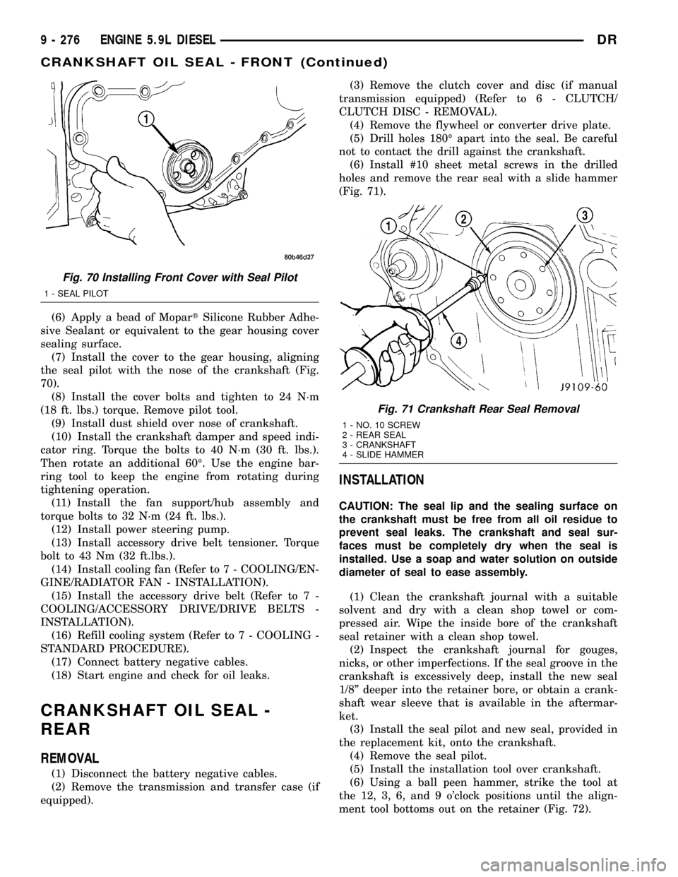
(7) Install the cover to the gear housing, aligning
the seal pilot with the nose of the crankshaft (Fig.
70).
(8) Install the cover bolts and tighten to 24 N´m
(18 ft. lbs.) torque. Remove pilot tool.
(9) Install dust shield over nose of crankshaft.
(10) Install the crankshaft damper and speed indi-
cator ring. Torque the bolts to 40 N´m (30 ft. lbs.).
Then rotate an additional 60É. Use the engine bar-
ring tool to keep the engine from rotating during
tightening operation.
(11) Install the fan support/hub assembly and
torque bolts to 32 N´m (24 ft. lbs.).
(12) Install power steering pump.
(13) Install accessory drive belt tensioner. Torque
bolt to 43 Nm (32 ft.lbs.).
(14) Install cooling fan (Refer to 7 - COOLING/EN-
GINE/RADIATOR FAN - INSTALLATION).
(15) Install the accessory drive belt (Refer to 7 -
COOLING/ACCESSORY DRIVE/DRIVE BELTS -
INSTALLATION).
(16) Refill cooling system (Refer to 7 - COOLING -
STANDARD PROCEDURE).
(17) Connect battery negative cables.
(18) Start engine and check for oil leaks.
CRANKSHAFT OIL SEAL -
REAR
REMOVAL
(1) Disconnect the battery negative cables.
(2) Remove the transmission and transfer case (if
equipped).(3) Remove the clutch cover and disc (if manual
transmission equipped) (Refer to 6 - CLUTCH/
CLUTCH DISC - REMOVAL).
(4) Remove the flywheel or converter drive plate.
(5) Drill holes 180É apart into the seal. Be careful
not to contact the drill against the crankshaft.
(6) Install #10 sheet metal screws in the drilled
holes and remove the rear seal with a slide hammer
(Fig. 71).
INSTALLATION
CAUTION: The seal lip and the sealing surface on
the crankshaft must be free from all oil residue to
prevent seal leaks. The crankshaft and seal sur-
faces must be completely dry when the seal is
installed. Use a soap and water solution on outside
diameter of seal to ease assembly.
(1) Clean the crankshaft journal with a suitable
solvent and dry with a clean shop towel or com-
pressed air. Wipe the inside bore of the crankshaft
seal retainer with a clean shop towel.
(2) Inspect the crankshaft journal for gouges,
nicks, or other imperfections. If the seal groove in the
crankshaft is excessively deep, install the new seal
1/8º deeper into the retainer bore, or obtain a crank-
shaft wear sleeve that is available in the aftermar-
ket.
(3) Install the seal pilot and new seal, provided in
the replacement kit, onto the crankshaft.
(4) Remove the seal pilot.
(5) Install the installation tool over crankshaft.
(6) Using a ball peen hammer, strike the tool at
the 12, 3, 6, and 9 o'clock positions until the align-
ment tool bottoms out on the retainer (Fig. 72).
Fig. 70 Installing Front Cover with Seal Pilot
1 - SEAL PILOT
Fig. 71 Crankshaft Rear Seal Removal
1 - NO. 10 SCREW
2 - REAR SEAL
3 - CRANKSHAFT
4 - SLIDE HAMMER
9 - 276 ENGINE 5.9L DIESELDR
CRANKSHAFT OIL SEAL - FRONT (Continued)
Page 1500 of 2627
(7) Install the flywheel or converter drive plate.
Tighten the bolts to 137 N´m (101 ft. lbs.) torque.
(8) Install the clutch cover and disc (if equipped)
(Refer to 6 - CLUTCH/CLUTCH DISC - INSTALLA-
TION).
(9) Install the transmission and transfer case (if
equipped).
(10) Lower vehicle.
(11) Connect battery negative cables.
(12) Check engine oil level and adjust, if necessary.
(13) Start engine and check for oil leaks.
CRANKSHAFT REAR OIL SEAL
RETAINER
REMOVAL
(1) Disconnect the battery negative cables.
(2) Raise vehicle on hoist.
(3) Remove the oil pan drain plug and drain the
engine oil. Re-install plug and torque to 50 N´m (44
ft. lbs.) torque.
(4) Remove transmission and transfer case (if
equipped) from vehicle.
(5)
Remove flywheel or torque converter drive plate.
(6) Disconnect starter cables from starter motor.
(7) Remove starter motor (Refer to 8 - ELECTRI-
CAL/STARTING/STARTER MOTOR - REMOVAL)
and transmission adapter plate assembly.
(8) Remove four (4) oil pan rear bolts. Slide a
feeler gauge between the seal retainer and oil pan
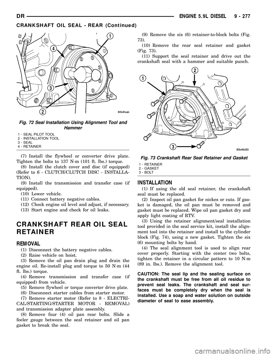
gasket to break the seal.(9) Remove the six (6) retainer-to-block bolts (Fig.
73).
(10) Remove the rear seal retainer and gasket
(Fig. 73).
(11) Support the seal retainer and drive out the
crankshaft seal with a hammer and suitable punch.
INSTALLATION
(1) If using the old seal retainer, the crankshaft
seal must be replaced.
(2) Inspect oil pan gasket for nickes or cuts. If gas-
ket is damaged, the oil pan must be removed and
gasket must be replaced. Wipe oil pan gasket dry and
apply light coating of RTV.
(3) Using the retainer alignment/seal installation
tool provided in the seal service kit, install the align-
ment tool into the retainer and install to the cylinder
block (Fig. 74), using a new gasket. Tighten the six
(6) mounting bolts by hand.
(4) The seal alignment tool is used to align rear
cover properly. Starting with the center two bolts,
tighten the retainer in a circular pattern to 10 N´m
(89 in. lbs.). Remove the alignment tool.
CAUTION: The seal lip and the sealing surface on
the crankshaft must be free from all oil residue to
prevent seal leaks. The crankshaft and seal sur-
faces must be completely dry when the seal is
installed. Use a soap and water solution on outside
diameter of seal to ease assembly.
Fig. 72 Seal Installation Using Alignment Tool and
Hammer
1 - SEAL PILOT TOOL
2 - INSTALLATION TOOL
3 - SEAL
4 - RETAINER
Fig. 73 Crankshaft Rear Seal Retainer and Gasket
1 - RETAINER
2 - GASKET
3 - BOLT
DRENGINE 5.9L DIESEL 9 - 277
CRANKSHAFT OIL SEAL - REAR (Continued)
Page 1501 of 2627
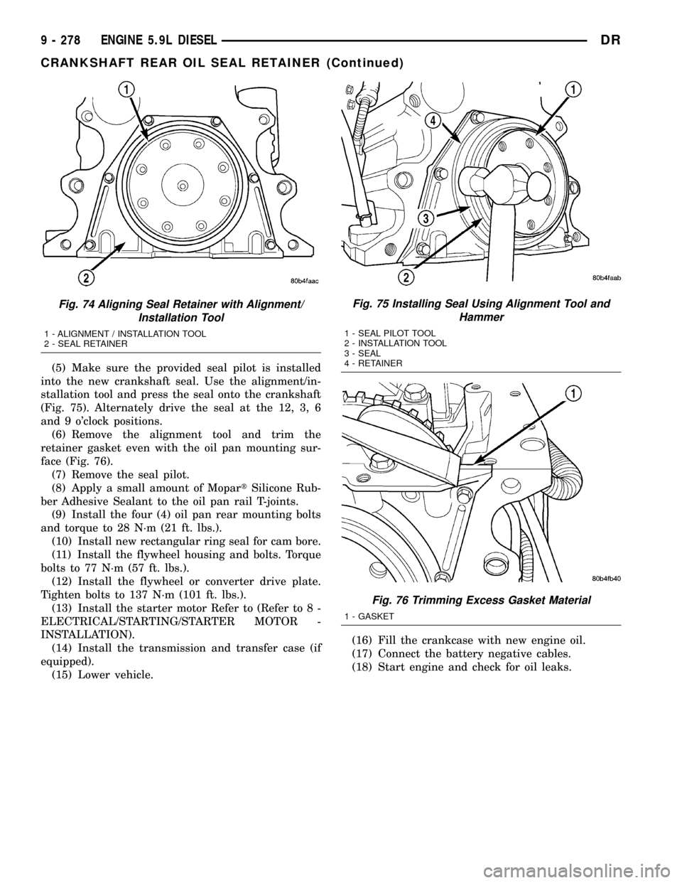
(5) Make sure the provided seal pilot is installed
into the new crankshaft seal. Use the alignment/in-
stallation tool and press the seal onto the crankshaft
(Fig. 75). Alternately drive the seal at the 12, 3, 6
and 9 o'clock positions.
(6) Remove the alignment tool and trim the
retainer gasket even with the oil pan mounting sur-
face (Fig. 76).
(7) Remove the seal pilot.
(8) Apply a small amount of MopartSilicone Rub-
ber Adhesive Sealant to the oil pan rail T-joints.
(9) Install the four (4) oil pan rear mounting bolts
and torque to 28 N´m (21 ft. lbs.).
(10) Install new rectangular ring seal for cam bore.
(11) Install the flywheel housing and bolts. Torque
bolts to 77 N´m (57 ft. lbs.).
(12) Install the flywheel or converter drive plate.
Tighten bolts to 137 N´m (101 ft. lbs.).
(13) Install the starter motor Refer to (Refer to 8 -
ELECTRICAL/STARTING/STARTER MOTOR -
INSTALLATION).
(14) Install the transmission and transfer case (if
equipped).
(15) Lower vehicle.(16) Fill the crankcase with new engine oil.
(17) Connect the battery negative cables.
(18) Start engine and check for oil leaks.
Fig. 74 Aligning Seal Retainer with Alignment/
Installation Tool
1 - ALIGNMENT / INSTALLATION TOOL
2 - SEAL RETAINER
Fig. 75 Installing Seal Using Alignment Tool and
Hammer
1 - SEAL PILOT TOOL
2 - INSTALLATION TOOL
3 - SEAL
4 - RETAINER
Fig. 76 Trimming Excess Gasket Material
1 - GASKET
9 - 278 ENGINE 5.9L DIESELDR
CRANKSHAFT REAR OIL SEAL RETAINER (Continued)