1998 DODGE RAM 1500 Front lamp
[x] Cancel search: Front lampPage 1689 of 2627

LINKAGE - LINK/COIL
TABLE OF CONTENTS
page page
LINKAGE - LINK/COIL
DESCRIPTION.........................34
STANDARD PROCEDURE - LUBRICATION....34
SPECIFICATIONS
TORQUE CHART......................35
SPECIAL TOOLS
STEERING LINKAGE...................35
DAMPER
REMOVAL.............................36
INSTALLATION.........................36
DRAG LINK
REMOVAL.............................36INSTALLATION.........................36
PITMAN ARM
REMOVAL.............................36
INSTALLATION.........................37
TIE ROD END
REMOVAL.............................37
INSTALLATION.........................37
TRACK BAR
REMOVAL.............................38
INSTALLATION.........................38
LINKAGE - LINK/COIL
DESCRIPTION
The steering linkage is comprised of a tie rod end, tie
rod, drag link, steering damper and pitman arm (Fig. 1).
CAUTION: If any steering components are replaced
or serviced an alignment must be performed.
NOTE: To avoid damaging ball stud seals, use
Puller C-3894±A or an appropriate puller to remove
tie rod ends (Fig. 2).
STANDARD PROCEDURE - LUBRICATION
Periodic lubrication of the steering system compo-
nents is required. Refer to Lubrication And Mainte-
nance for the recommended maintenance schedule.
The following components must be lubricated:
²Tie rod
²Tie rod end
²Drag link
Fig. 1 LINK/COIL FRONT SUSPENSION
1 - STABILIZER BAR
2 - PITMAN ARM
3 - STEERING GEAR
4 - STABILIZER LINK
5 - TIE ROD ENDS
6 - LOWER SUSPENSION ARMS
7 - DRAG LINK
8 - TRACK BAR
9 - DAMPER
10 - UPPER SUSPENSION ARM
Fig. 2 Ball Stud Puller
1 - CLAMP
2 - ADJUSTMENT SLEEVE
3 - PULLER TOOL C-3894±A
4 - SEAL
5 - TIE-ROD END
19 - 34 LINKAGE - LINK/COILDR
Page 1778 of 2627

(5) Install new oil seal in front bearing retainer
with Installer 6052 (Fig. 112). Use one or two wood
blocks to support retainer as shown. Lubricate seal
lip with petroleum jelly after installation.
(6) Clean contact surfaces of gear case and front
bearing retainer with a wax and grease remover.
(7) Apply Mopar Silicone Sealer or equivalent to
flange surface of front bearing retainer (Fig. 113).
(8) Install front bearing retainer over drive gear
and start it into case.
(9) Start front bearing retainer in gear case. Verify
retainer lube channel is at the top-center(12
O'clock)position (Fig. 113).(10) Align front bearing retainer bolt holes and tap
retainer into place with plastic mallet. Installnew
retainer bolts and tighten to 30 N´m (22 ft. lbs.) (Fig.
114).
NOTE: Never reuse the old bolts.
MAINSHAFT END PLAY
(1) Install mainshaft rear bearing cup in case and
over bearing. Tap bearing cup into place with plastic
mallet.
(2) Install rear bearing plate to hold mainshaft
and rear bearing in position (Fig. 115).
NOTE: Do not install any end play shims at this
time.
(3) Tighten rear bearing plate bolts securely.
(4) Place gear case in upright position on bench.
Either cut hole in bench to accept drive gear and
front retainer or use C-clamps to secure transmission
on bench.
NOTE: Do not leave transmission unsupported.
(5) Install Extension Rod 8161 into a suitable
threaded hole in rear of case.
(6) Mount dial indicator on extension rod and posi-
tion indicator plunger against end of mainshaft.
(7) Move mainshaft forward to remove all play
then zero dial indicator.
(8) Move mainshaft upward and record dial indica-
tor reading. Move mainshaft with pry tool positioned
between drive gear and case.
(9) End play should be 0.051-0.15 mm (0.002-0.006
in.). Select fit shims are available to adjust end play.
If end play adjustment is required, remove bearing
plate and install necessary shim.
(10) Reinstall rear bearing plate with oil hole in
bearing plate at the top (Fig. 115).
(11) Apply Mopar Lock N' Seal or equivalent to
bearing plate bolt threads. Install and tighten bolts
to 23 N´m (200 in. lbs.).
Fig. 112 BEARING RETAINER OIL SEAL
1 - INSTALLER
2 - RETAINER
3 - WOOD BLOCK
Fig. 113 LOCATION OF FRONT RETAINER LUBE
CHANNEL
1 - LUBE CHANNEL
2 - FRONT RETAINER
3 - APPLY GASKET MAKER HERE
Fig. 114 FRONT BEARING RETAINER
1 - DRIVE GEAR
2 - FRONT BEARING RETAINER
DRMANUAL TRANSMISSION - NV4500 21 - 75
MANUAL TRANSMISSION - NV4500 (Continued)
Page 1784 of 2627

SPECIFICATIONS
TORQUE SPECIFICATIONS
DESCRIPTION N´m Ft. Lbs. In. Lbs.
Switch, Back-up Lamp 22-34 16-25 -
Countershaft Bearing Plate Bolts 19-26 14-19 170-230
Fifth Gear Nut 366-380 270-280 -
Fifth Gear Nut Clamp Bolt 13.5 10 -
Drain and Fill Plug 34-47 25-35 -
Front Bearing Retainer Bolts 27-34 20-25 235-305
Mainshaft Bearing Plate Bolts 19-26 14-19 170-230
PTO Cover Bolts 27-54 20-40 -
Extension/Adapter Housing Bolts 41-68 30-50 -
Shift Mechanism Cover Bolts 27-31 20-23 -
Transmission Bolts 108 80 -
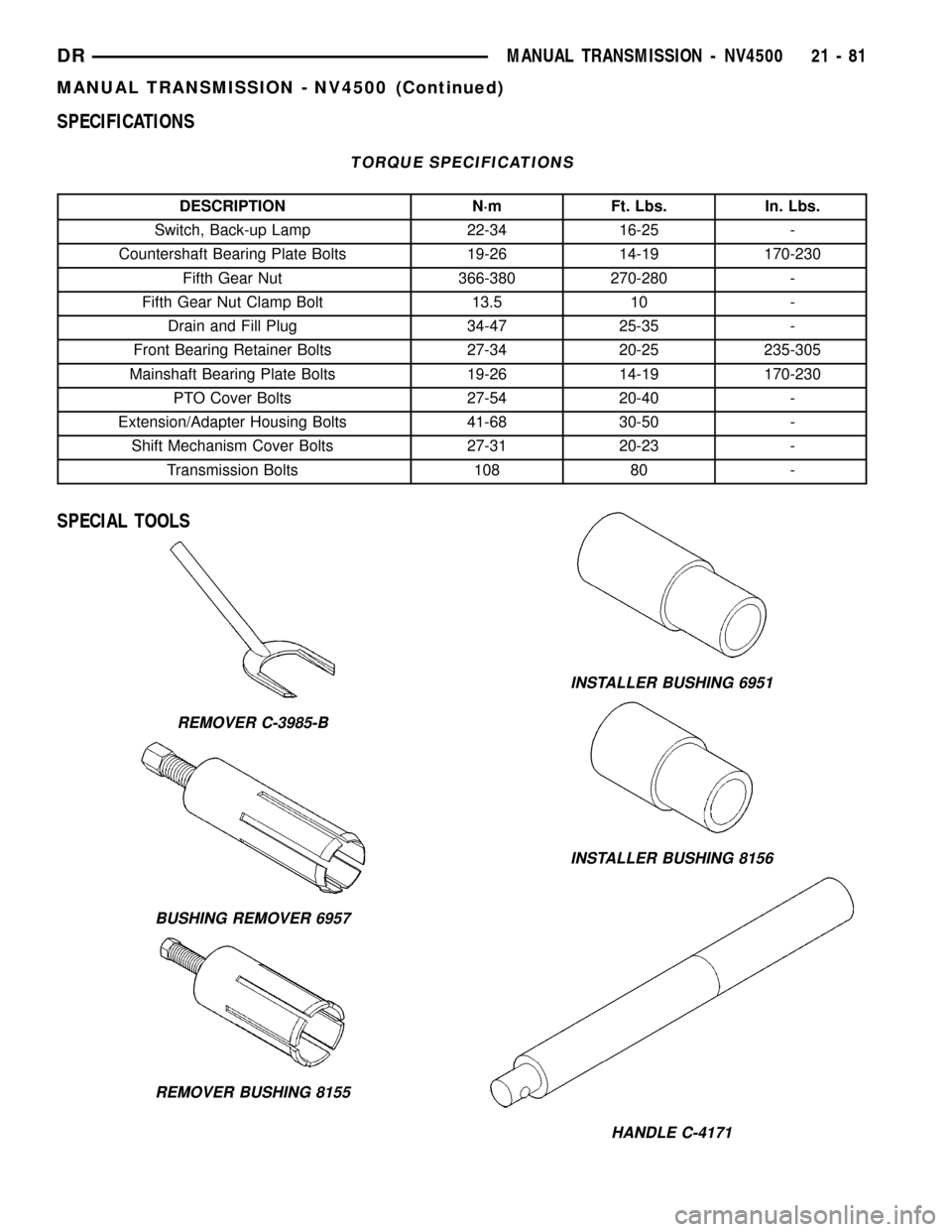
SPECIAL TOOLS
REMOVER C-3985-B
BUSHING REMOVER 6957
REMOVER BUSHING 8155
INSTALLER BUSHING 6951
INSTALLER BUSHING 8156
HANDLE C-4171
DRMANUAL TRANSMISSION - NV4500 21 - 81
MANUAL TRANSMISSION - NV4500 (Continued)
Page 1855 of 2627

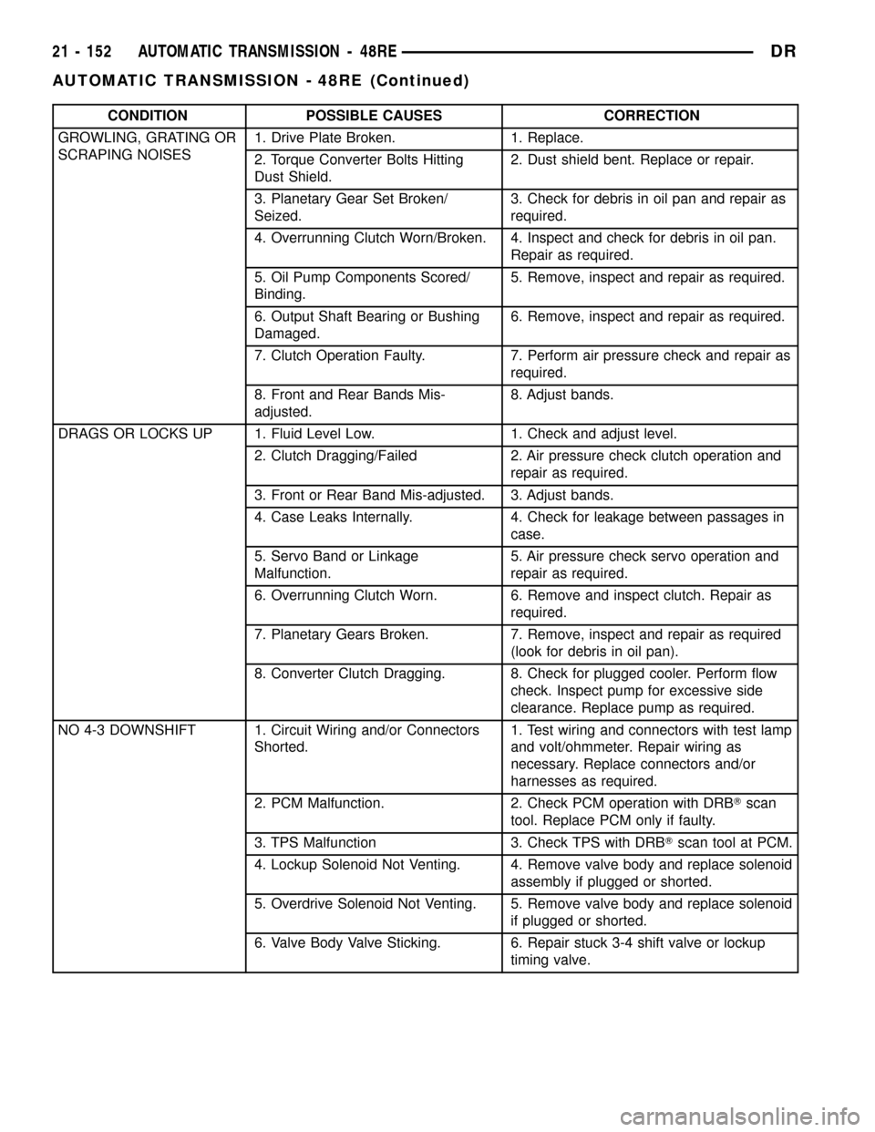
CONDITION POSSIBLE CAUSES CORRECTION
GROWLING, GRATING OR
SCRAPING NOISES1. Drive Plate Broken. 1. Replace.
2. Torque Converter Bolts Hitting
Dust Shield.2. Dust shield bent. Replace or repair.
3. Planetary Gear Set Broken/
Seized.3. Check for debris in oil pan and repair as
required.
4. Overrunning Clutch Worn/Broken. 4. Inspect and check for debris in oil pan.
Repair as required.
5. Oil Pump Components Scored/
Binding.5. Remove, inspect and repair as required.
6. Output Shaft Bearing or Bushing
Damaged.6. Remove, inspect and repair as required.
7. Clutch Operation Faulty. 7. Perform air pressure check and repair as
required.
8. Front and Rear Bands Mis-
adjusted.8. Adjust bands.
DRAGS OR LOCKS UP 1. Fluid Level Low. 1. Check and adjust level.
2. Clutch Dragging/Failed 2. Air pressure check clutch operation and
repair as required.
3. Front or Rear Band Mis-adjusted. 3. Adjust bands.
4. Case Leaks Internally. 4. Check for leakage between passages in
case.
5. Servo Band or Linkage
Malfunction.5. Air pressure check servo operation and
repair as required.
6. Overrunning Clutch Worn. 6. Remove and inspect clutch. Repair as
required.
7. Planetary Gears Broken. 7. Remove, inspect and repair as required
(look for debris in oil pan).
8. Converter Clutch Dragging. 8. Check for plugged cooler. Perform flow
check. Inspect pump for excessive side
clearance. Replace pump as required.
NO 4-3 DOWNSHIFT 1. Circuit Wiring and/or Connectors
Shorted.1. Test wiring and connectors with test lamp
and volt/ohmmeter. Repair wiring as
necessary. Replace connectors and/or
harnesses as required.
2. PCM Malfunction. 2. Check PCM operation with DRBTscan
tool. Replace PCM only if faulty.
3. TPS Malfunction 3. Check TPS with DRBTscan tool at PCM.
4. Lockup Solenoid Not Venting. 4. Remove valve body and replace solenoid
assembly if plugged or shorted.
5. Overdrive Solenoid Not Venting. 5. Remove valve body and replace solenoid
if plugged or shorted.
6. Valve Body Valve Sticking. 6. Repair stuck 3-4 shift valve or lockup
timing valve.
21 - 152 AUTOMATIC TRANSMISSION - 48REDR
AUTOMATIC TRANSMISSION - 48RE (Continued)
Page 1859 of 2627

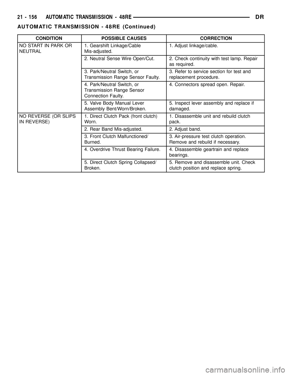
CONDITION POSSIBLE CAUSES CORRECTION
NO START IN PARK OR
NEUTRAL1. Gearshift Linkage/Cable
Mis-adjusted.1. Adjust linkage/cable.
2. Neutral Sense Wire Open/Cut. 2. Check continuity with test lamp. Repair
as required.
3. Park/Neutral Switch, or
Transmission Range Sensor Faulty.3. Refer to service section for test and
replacement procedure.
4. Park/Neutral Switch, or
Transmission Range Sensor
Connection Faulty.4. Connectors spread open. Repair.
5. Valve Body Manual Lever
Assembly Bent/Worn/Broken.5. Inspect lever assembly and replace if
damaged.
NO REVERSE (OR SLIPS
IN REVERSE)1. Direct Clutch Pack (front clutch)
Worn.1. Disassemble unit and rebuild clutch
pack.
2. Rear Band Mis-adjusted. 2. Adjust band.
3. Front Clutch Malfunctioned/
Burned.3. Air-pressure test clutch operation.
Remove and rebuild if necessary.
4. Overdrive Thrust Bearing Failure. 4. Disassemble geartrain and replace
bearings.
5. Direct Clutch Spring Collapsed/
Broken.5. Remove and disassemble unit. Check
clutch position and replace spring.
21 - 156 AUTOMATIC TRANSMISSION - 48REDR
AUTOMATIC TRANSMISSION - 48RE (Continued)
Page 1868 of 2627

(27) Note that overrunning clutch race will remain
on splines of low-reverse drum after removal (Fig.
36).The race is a permanent press fit on the
hub splines. Do not attempt to remove the race.
(28) Remove overrunning clutch assembly (Fig.
37). Assembly can be removed without displacing
rollers and springs if care is exercised. Note position
of rollers and springs for assembly reference.
(29) Remove rear band adjusting lever and reac-
tion pin.
(30) Remove rear band.
(31) Compress front servo rod guide with large
C-clamp and Tool C-4470, or Compressor Tool
C-3422-B (Fig. 38). Compress guide only enough to
permit snap-ring removal (about 1/8 in.).
(32) Remove servo piston snap-ring (Fig. 38).
Unseat one end of ring. Then carefully work removal
tool around back of ring until free of ring groove.
Exercise caution when removing snap-ring.
Servo bore can be scratched or nicked if care is
not exercised.
Fig. 38 Front Servo Retaining Snap-Ring
1 - C-CLAMP
2 - FRONT SERVO ROD GUIDE
3 - SNAP-RING
4 - TOOL C-4470
Fig. 36 Overrunning Clutch Race Position On
Low-Reverse Drum
1 - OVERRUNNING CLUTCH RACE
2 - LOW-REVERSE DRUM
Fig. 37 Overrunning Clutch
1 - CLUTCH CAM
2 - OVERRUNNING CLUTCH ASSEMBLY
DRAUTOMATIC TRANSMISSION - 48RE 21 - 165
AUTOMATIC TRANSMISSION - 48RE (Continued)
Page 1869 of 2627

(33) Remove tools and remove servo piston and
spring.
(34) Compress rear servo piston with C-clamp and
Tool C-4470, or Valve Spring Compressor C-3422-B
(Fig. 39). Compress servo spring retainer only
enough to permit snap-ring removal.
(35) Remove servo piston snap-ring (Fig. 39). Start
one end of ring out of bore. Then carefully work
removal tool around back of snap-ring until free of
ring groove.Exercise caution when removing
snap-ring. Servo bore can be scratched or
nicked if care is not exercised.
(36) Remove tools and remove rear servo retainer,
spring and piston assembly.
CLEANING
Clean the case in a solvent tank. Flush the case
bores and fluid passages thoroughly with solvent.
Dry the case and all fluid passages with compressed
air. Be sure all solvent is removed from the case and
that all fluid passages are clear.
NOTE: Do not use shop towels or rags to dry the
case (or any other transmission component) unless
they are made from lint-free materials. Lint will stick
to case surfaces and transmission components and
circulate throughout the transmission after assem-
bly. A sufficient quantity of lint can block fluid pas-
sages and interfere with valve body operation.
Lubricate transmission parts with MopartATF +4,
Automatic Transmission fluid, during overhaul and
assembly. Use petroleum jelly to prelubricate seals,
O-rings, and thrust washers. Petroleum jelly can also
be used to hold parts in place during reassembly.
INSPECTION
Inspect the case for cracks, porous spots, worn
bores, or damaged threads. Damaged threads can be
repaired with Helicoil thread inserts. However, the
case will have to be replaced if it exhibits any type of
damage or wear.
Lubricate the front band adjusting screw threads
with petroleum jelly and thread the screw part-way
into the case. Be sure the screw turns freely.
Inspect the transmission bushings during overhaul.
Bushing condition is important as worn, scored bush-
ings contribute to low pressures, clutch slip and
accelerated wear of other components. However, do
not replace bushings as a matter of course. Replace
bushings only when they are actually worn, or
scored.
The use of crocus cloth is permissible where neces-
sary, providing it is used carefully. When used on
shafts, or valves, use extreme care to avoid rounding
off sharp edges. Sharp edges are vital as they pre-
vent foreign matter from getting between the valve
and valve bore.
Do not reuse oil seals, gaskets, seal rings, or
O-rings during overhaul. Replace these parts as a
matter of course. Also do not reuse snap rings or
E-clips that are bent or distorted. Replace these parts
as well.
ASSEMBLY
Do not allow dirt, grease, or foreign material to
enter the case or transmission components during
assembly. Keep the transmission case and compo-
nents clean. Also make sure the tools and workbench
area used for reassembly operations are equally
clean.
Shop towels used for wiping off tools and your
hands must be made fromlint freematerials. Lint
will stick to transmission parts and could interfere
with valve operation or even restrict fluid passages.
Lubricate transmission clutch and gear compo-
nents with MopartATF +4 during reassembly. Soak
clutch discs in transmission fluid before installation.
Use petroleum jelly on piston seals and o-rings to
ease installation. Petroleum jelly can also be used to
lubricate and hold thrust washers and plates in posi-
tion during assembly.
Do not use chassis grease, bearing grease,
white grease, or similar lubricants on any part.
These types of lubricants can eventually block or
restrict fluid passages and valve operation. Use
petroleum jelly only.
Do not force parts into place. The transmission
components and sub-assemblies are easily installed
by hand when properly aligned. If a part seems dif-
ficult to install, it is either misaligned or incorrectly
Fig. 39 Rear Servo Retaining Snap-Ring
1 - TOOL C-4470
2 - C-CLAMP
3 - REAR SERVO SPRING RETAINER
4 - RETAINER SNAP-RING
21 - 166 AUTOMATIC TRANSMISSION - 48REDR
AUTOMATIC TRANSMISSION - 48RE (Continued)
Page 1870 of 2627

assembled. Verify that thrust washers, thrust plates
and seal rings are correctly positioned.
The planetary geartrain, front/rear clutch assem-
blies and oil pump are all much easier to install
when the transmission case is upright. Either tilt the
case upward with wood blocks, or cut a hole in the
bench large enough for the intermediate shaft and
rear support. Then lower the shaft and support into
the hole and support the rear of the case directly on
the bench.
FRONT/REAR SERVO
(1) Lubricate rear servo piston seal with ATF +4.
Lubricate servo bore in case with ATF +4.
(2) Install rear servo piston in case. Position piston
at slight angle to bore and insert piston with twisting
motion (Fig. 40).
(3) Install rear servo spring and retainer in case
bore (Fig. 41). Be sure spring is seated on piston.
(4) Compress rear servo piston with C-clamp or
Valve Spring Compressor C-3422-B and install servo
piston snap-ring (Fig. 42).
(5) Lubricate front servo piston components and
servo bore in case with transmission fluid.
(6) Install front servo piston in bore. Carefully
ªrunº small, suitable tool around piston ring to press
it back into groove and ease installation (Fig. 43).
Rotate piston into bore at same time. Rock piston
slightly to ease piston ring past snap-ring groove and
into bore.
Fig. 40 Rear Servo Piston
1 - REAR SERVO PISTON
Fig. 41 Rear Servo Piston Spring And Retainer
1 - PISTON SPRING
2 - REAR SERVO PISTON
3 - SPRING RETAINER
Fig. 42 Rear Servo Snap Ring
1 - TOOL C-4470
2 - C-CLAMP
3 - REAR SERVO SPRING RETAINER
4 - RETAINER SNAP-RING
DRAUTOMATIC TRANSMISSION - 48RE 21 - 167
AUTOMATIC TRANSMISSION - 48RE (Continued)