1998 DODGE RAM 1500 Front lamp
[x] Cancel search: Front lampPage 2207 of 2627
OIL PUMP AND REAR CASE
Lubricate the oil pump components with transmis-
sion fluid before installation. Prime the oil pickup
tube by pouring a little oil into the tube before instal-
lation.
CAUTION: Do not remove the bolts holding the oil
pump cover to the rear case half. The oil pump
cover is aligned to the rear output shaft inner bear-
ing race and will become mis-aligned if the bolts
are loosened. If the transfer case failure has gener-
ated any debris which may have become trapped in
the oil pump. the rear case and oil pump assembly
MUST be replaced.
(1) Install new o-ring in pickup tube inlet of oil
pump.
(2) Insert oil pickup tube into the oil pump.
(3) Apply bead of MopartGasket Maker, or equiv-
alent, to mating surface of front case. Keep sealer
bead width to maximum of 3/16 inch. Do not use
excessive amount of sealer as excess will be displaced
into case interior.
(4) Align oil pump with mainshaft and align shift
rail with bore in rear case. Then install rear case and
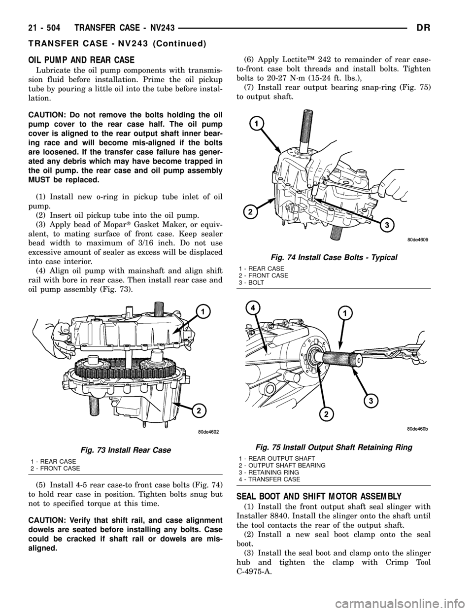
oil pump assembly (Fig. 73).
(5) Install 4-5 rear case-to front case bolts (Fig. 74)
to hold rear case in position. Tighten bolts snug but
not to specified torque at this time.
CAUTION: Verify that shift rail, and case alignment
dowels are seated before installing any bolts. Case
could be cracked if shaft rail or dowels are mis-
aligned.(6) Apply LoctiteŸ 242 to remainder of rear case-
to-front case bolt threads and install bolts. Tighten
bolts to 20-27 N´m (15-24 ft. lbs.),
(7) Install rear output bearing snap-ring (Fig. 75)
to output shaft.
SEAL BOOT AND SHIFT MOTOR ASSEMBLY
(1) Install the front output shaft seal slinger with
Installer 8840. Install the slinger onto the shaft until
the tool contacts the rear of the output shaft.
(2) Install a new seal boot clamp onto the seal
boot.
(3) Install the seal boot and clamp onto the slinger
hub and tighten the clamp with Crimp Tool
C-4975-A.
Fig. 73 Install Rear Case
1 - REAR CASE
2 - FRONT CASE
Fig. 74 Install Case Bolts - Typical
1 - REAR CASE
2 - FRONT CASE
3 - BOLT
Fig. 75 Install Output Shaft Retaining Ring
1 - REAR OUTPUT SHAFT
2 - OUTPUT SHAFT BEARING
3 - RETAINING RING
4 - TRANSFER CASE
21 - 504 TRANSFER CASE - NV243DR
TRANSFER CASE - NV243 (Continued)
Page 2210 of 2627
EXTENSION HOUSING SEAL
REMOVAL
(1) Raise and support vehicle.
(2) Remove rear propeller shaft. (Refer to 3 - DIF-
FERENTIAL & DRIVELINE/PROPELLER SHAFT/
PROPELLER SHAFT - REMOVAL)
(3) Using a suitable pry tool or slide-hammer
mounted screw, remove the extension housing seal.
INSTALLATION
(1) Clean fluid residue from sealing surface and
inspect for defects.
(2) Using Installer D-163, install seal in extension
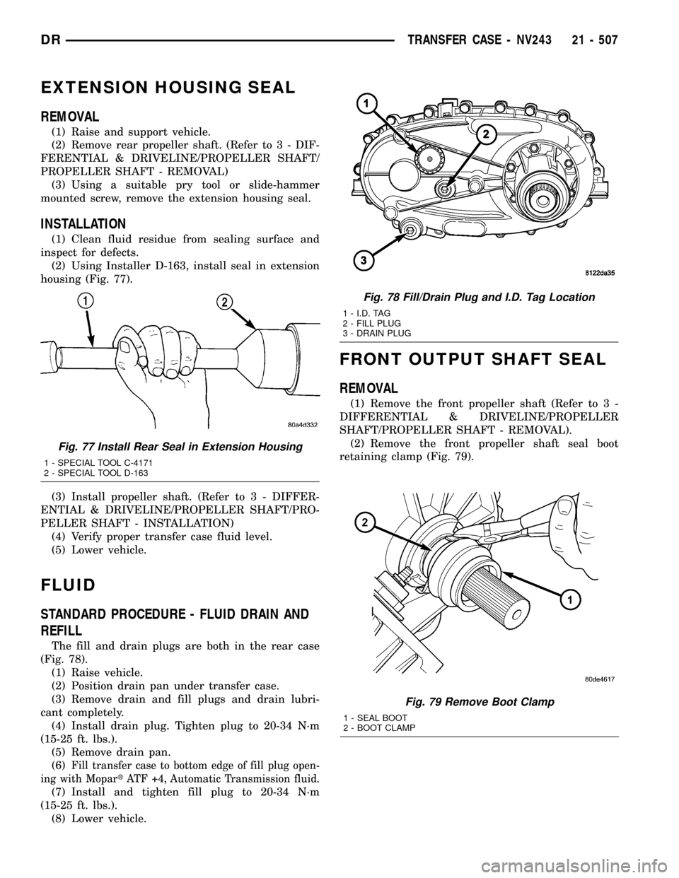
housing (Fig. 77).
(3) Install propeller shaft. (Refer to 3 - DIFFER-
ENTIAL & DRIVELINE/PROPELLER SHAFT/PRO-
PELLER SHAFT - INSTALLATION)
(4) Verify proper transfer case fluid level.
(5) Lower vehicle.
FLUID
STANDARD PROCEDURE - FLUID DRAIN AND
REFILL
The fill and drain plugs are both in the rear case
(Fig. 78).
(1) Raise vehicle.
(2) Position drain pan under transfer case.
(3) Remove drain and fill plugs and drain lubri-
cant completely.
(4) Install drain plug. Tighten plug to 20-34 N´m
(15-25 ft. lbs.).
(5) Remove drain pan.
(6)
Fill transfer case to bottom edge of fill plug open-
ing with MopartATF +4, Automatic Transmission fluid.
(7) Install and tighten fill plug to 20-34 N´m
(15-25 ft. lbs.).
(8) Lower vehicle.
FRONT OUTPUT SHAFT SEAL
REMOVAL
(1) Remove the front propeller shaft (Refer to 3 -
DIFFERENTIAL & DRIVELINE/PROPELLER
SHAFT/PROPELLER SHAFT - REMOVAL).
(2) Remove the front propeller shaft seal boot
retaining clamp (Fig. 79).
Fig. 79 Remove Boot Clamp
1 - SEAL BOOT
2 - BOOT CLAMP
Fig. 77 Install Rear Seal in Extension Housing
1 - SPECIAL TOOL C-4171
2 - SPECIAL TOOL D-163
Fig. 78 Fill/Drain Plug and I.D. Tag Location
1 - I.D. TAG
2 - FILL PLUG
3 - DRAIN PLUG
DRTRANSFER CASE - NV243 21 - 507
Page 2211 of 2627
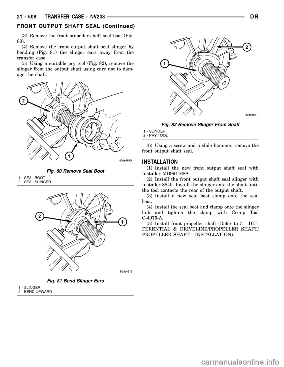
(3) Remove the front propeller shaft seal boot (Fig.
80).
(4) Remove the front output shaft seal slinger by
bending (Fig. 81) the slinger ears away from the
transfer case.
(5) Using a suitable pry tool (Fig. 82), remove the
slinger from the output shaft using care not to dam-
age the shaft.
(6) Using a screw and a slide hammer, remove the
front output shaft seal.
INSTALLATION
(1) Install the new front output shaft seal with
Installer MB991168A
(2) Install the front output shaft seal slinger with
Installer 8840. Install the slinger onto the shaft until
the tool contacts the rear of the output shaft.
(3) Install a new seal boot clamp onto the seal
boot.
(4) Install the seal boot and clamp onto the slinger
hub and tighten the clamp with Crimp Tool
C-4975-A.
(5) Install front propeller shaft (Refer to 3 - DIF-
FERENTIAL & DRIVELINE/PROPELLER SHAFT/
PROPELLER SHAFT - INSTALLATION).Fig. 80 Remove Seal Boot
1 - SEAL BOOT
2 - SEAL SLINGER
Fig. 81 Bend Slinger Ears
1 - SLINGER
2 - BEND UPWARD
Fig. 82 Remove Slinger From Shaft
1 - SLINGER
2-PRYTOOL
21 - 508 TRANSFER CASE - NV243DR
FRONT OUTPUT SHAFT SEAL (Continued)
Page 2218 of 2627
(2) Remove the shift motor and mode sensor
assembly from the transfer case.
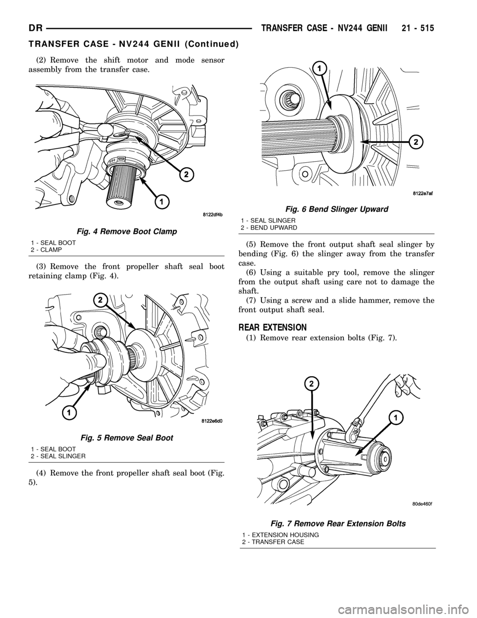
(3) Remove the front propeller shaft seal boot
retaining clamp (Fig. 4).
(4) Remove the front propeller shaft seal boot (Fig.
5).(5) Remove the front output shaft seal slinger by
bending (Fig. 6) the slinger away from the transfer
case.
(6) Using a suitable pry tool, remove the slinger
from the output shaft using care not to damage the
shaft.
(7) Using a screw and a slide hammer, remove the
front output shaft seal.
REAR EXTENSION
(1) Remove rear extension bolts (Fig. 7).
Fig. 7 Remove Rear Extension Bolts
1 - EXTENSION HOUSING
2 - TRANSFER CASE
Fig. 4 Remove Boot Clamp
1 - SEAL BOOT
2 - CLAMP
Fig. 5 Remove Seal Boot
1 - SEAL BOOT
2 - SEAL SLINGER
Fig. 6 Bend Slinger Upward
1 - SEAL SLINGER
2 - BEND UPWARD
DRTRANSFER CASE - NV244 GENII 21 - 515
TRANSFER CASE - NV244 GENII (Continued)
Page 2240 of 2627
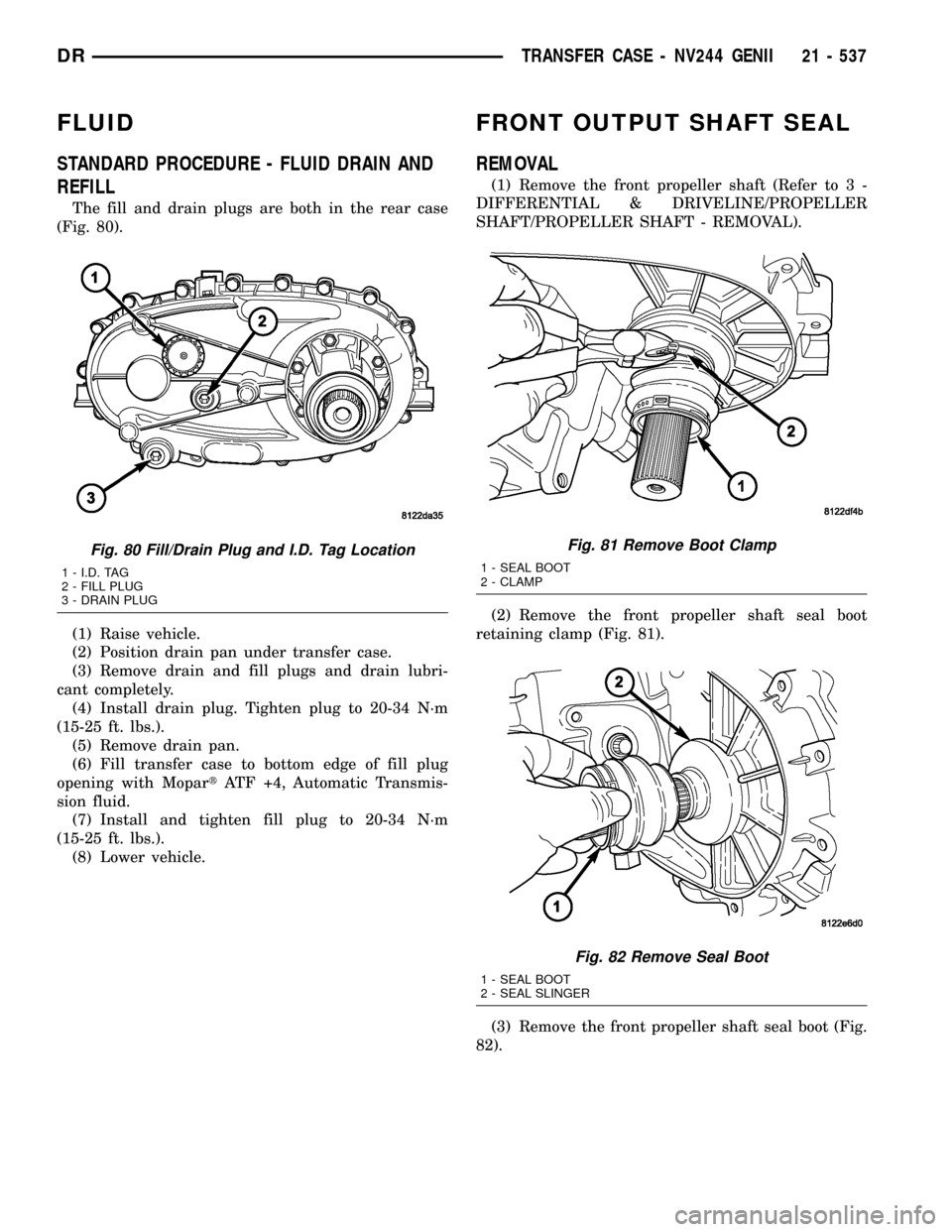
FLUID
STANDARD PROCEDURE - FLUID DRAIN AND
REFILL
The fill and drain plugs are both in the rear case
(Fig. 80).
(1) Raise vehicle.
(2) Position drain pan under transfer case.
(3) Remove drain and fill plugs and drain lubri-
cant completely.
(4) Install drain plug. Tighten plug to 20-34 N´m
(15-25 ft. lbs.).
(5) Remove drain pan.
(6) Fill transfer case to bottom edge of fill plug
opening with MopartATF +4, Automatic Transmis-
sion fluid.
(7) Install and tighten fill plug to 20-34 N´m
(15-25 ft. lbs.).
(8) Lower vehicle.
FRONT OUTPUT SHAFT SEAL
REMOVAL
(1) Remove the front propeller shaft (Refer to 3 -
DIFFERENTIAL & DRIVELINE/PROPELLER
SHAFT/PROPELLER SHAFT - REMOVAL).
(2) Remove the front propeller shaft seal boot
retaining clamp (Fig. 81).
(3) Remove the front propeller shaft seal boot (Fig.
82).
Fig. 80 Fill/Drain Plug and I.D. Tag Location
1 - I.D. TAG
2 - FILL PLUG
3 - DRAIN PLUG
Fig. 81 Remove Boot Clamp
1 - SEAL BOOT
2 - CLAMP
Fig. 82 Remove Seal Boot
1 - SEAL BOOT
2 - SEAL SLINGER
DRTRANSFER CASE - NV244 GENII 21 - 537
Page 2241 of 2627
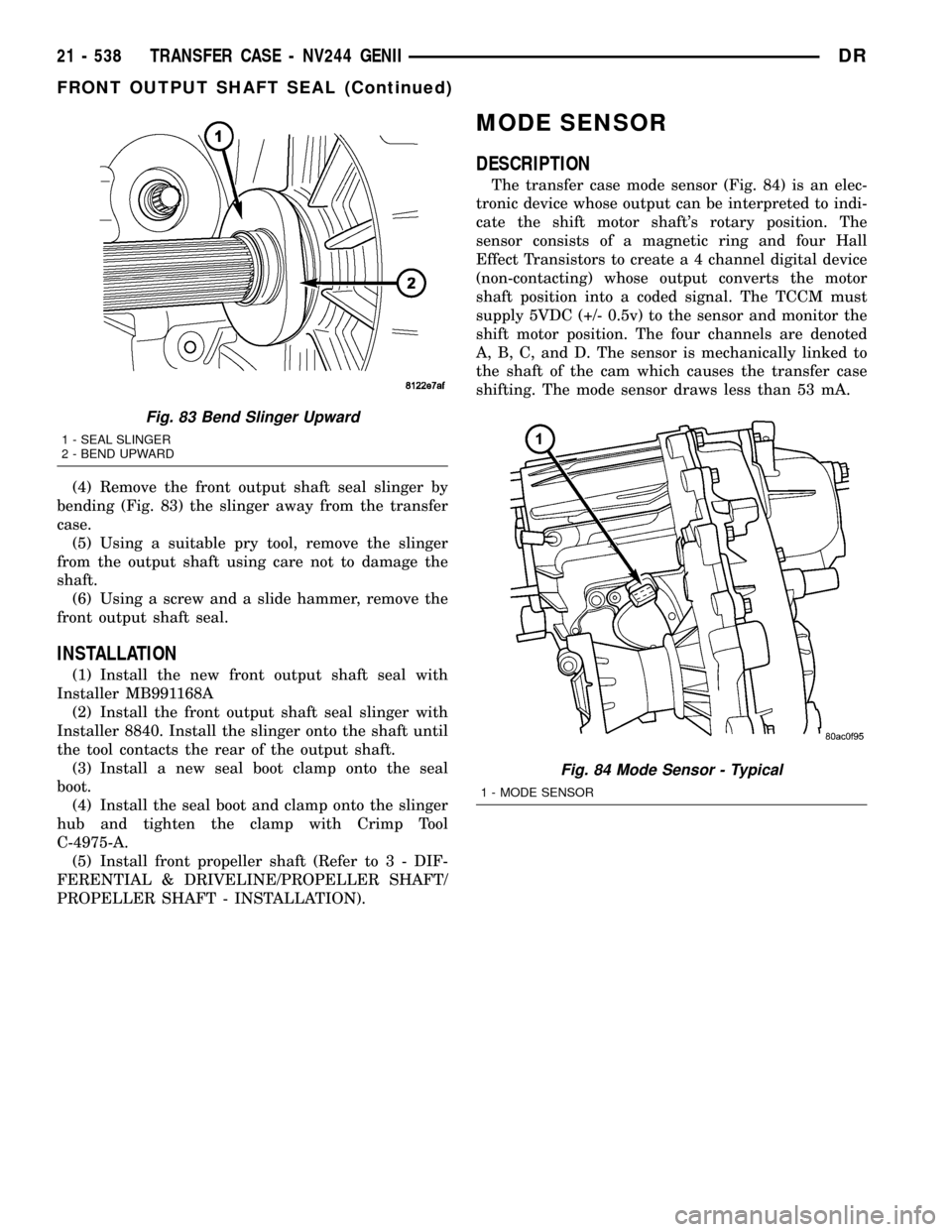
(4) Remove the front output shaft seal slinger by
bending (Fig. 83) the slinger away from the transfer
case.
(5) Using a suitable pry tool, remove the slinger
from the output shaft using care not to damage the
shaft.
(6) Using a screw and a slide hammer, remove the
front output shaft seal.
INSTALLATION
(1) Install the new front output shaft seal with
Installer MB991168A
(2) Install the front output shaft seal slinger with
Installer 8840. Install the slinger onto the shaft until
the tool contacts the rear of the output shaft.
(3) Install a new seal boot clamp onto the seal
boot.
(4) Install the seal boot and clamp onto the slinger
hub and tighten the clamp with Crimp Tool
C-4975-A.
(5) Install front propeller shaft (Refer to 3 - DIF-
FERENTIAL & DRIVELINE/PROPELLER SHAFT/
PROPELLER SHAFT - INSTALLATION).
MODE SENSOR
DESCRIPTION
The transfer case mode sensor (Fig. 84) is an elec-
tronic device whose output can be interpreted to indi-
cate the shift motor shaft's rotary position. The
sensor consists of a magnetic ring and four Hall
Effect Transistors to create a 4 channel digital device
(non-contacting) whose output converts the motor
shaft position into a coded signal. The TCCM must
supply 5VDC (+/- 0.5v) to the sensor and monitor the
shift motor position. The four channels are denoted
A, B, C, and D. The sensor is mechanically linked to
the shaft of the cam which causes the transfer case
shifting. The mode sensor draws less than 53 mA.
Fig. 83 Bend Slinger Upward
1 - SEAL SLINGER
2 - BEND UPWARD
Fig. 84 Mode Sensor - Typical
1 - MODE SENSOR
21 - 538 TRANSFER CASE - NV244 GENIIDR
FRONT OUTPUT SHAFT SEAL (Continued)
Page 2296 of 2627
BODY
TABLE OF CONTENTS
page page
BODY
WARNING
SAFETY PRECAUTIONS AND WARNINGS . . . 1
DIAGNOSIS AND TESTING
DIAGNOSIS AND TESTING - WATER LEAKS . 1
DIAGNOSIS AND TESTING - WIND NOISE . . . 2
STANDARD PROCEDURE
STANDARD PROCEDURE - BODY
LUBRICATION.........................3
STANDARD PROCEDURE - HEAT STAKING . . 3
STANDARD PROCEDURE - PLASTIC BODY
PANEL REPAIR........................3
STANDARD PROCEDURE - BUZZ, SQUEAK
& RATTLE...........................11
SPECIFICATIONS - TORQUE..............12SPECIAL TOOLS
BODY..............................14
TAILGATE..............................15
DOOR - FRONT.........................18
DOORS - REAR.........................28
EXTERIOR.............................36
HOOD.................................46
INSTRUMENT PANEL.....................49
INTERIOR..............................62
PAINT.................................73
SEATS................................75
STATIONARY GLASS.....................86
WEATHERSTRIP/SEALS...................91
BODY STRUCTURE......................95
BODY
WARNING
SAFETY PRECAUTIONS AND WARNINGS
WARNING: USE AN OSHA APPROVED BREATHING
FILTER WHEN SPRAYING PAINT OR SOLVENTS IN
A CONFINED AREA. PERSONAL INJURY CAN
RESULT.
²AVOID PROLONGED SKIN CONTACT WITH
PETROLEUM OR ALCOHOL ± BASED CLEANING
SOLVENTS. PERSONAL INJURY CAN RESULT.
²DO NOT STAND UNDER A HOISTED VEHICLE
THAT IS NOT PROPERLY SUPPORTED ON SAFETY
STANDS. PERSONAL INJURY CAN RESULT.
CAUTION: When holes must be drilled or punched
in an inner body panel, verify depth of space to the
outer body panel, electrical wiring, or other compo-
nents. Damage to vehicle can result.
²Do not weld exterior panels unless combustible
material on the interior of vehicle is removed from
the repair area. Fire or hazardous conditions, can
result.
²Always have a fire extinguisher ready for use
when welding.
²Disconnect the negative (-) cable clamp from
the battery when servicing electrical components
that are live when the ignition is OFF. Damage to
electrical system can result.²Do not use abrasive chemicals or compounds
on painted surfaces. Damage to finish can result.
²Do not use harsh alkaline based cleaning sol-
vents on painted or upholstered surfaces. Damage
to finish or color can result.
²Do not hammer or pound on plastic trim panel
when servicing interior trim. Plastic panels can
break.
DIAGNOSIS AND TESTING
DIAGNOSIS AND TESTING - WATER LEAKS
Water leaks can be caused by poor sealing,
improper body component alignment, body seam
porosity, missing plugs, or blocked drain holes. Cen-
trifugal and gravitational force can cause water to
drip from a location away from the actual leak point,
making leak detection difficult. All body sealing
points should be water tight in normal wet-driving
conditions. Water flowing downward from the front of
the vehicle should not enter the passenger or luggage
compartment. Moving sealing surfaces will not
always seal water tight under all conditions. At
times, side glass or door seals will allow water to
enter the passenger compartment during high pres-
sure washing or hard driving rain (severe) condi-
tions. Overcompensating on door or glass
adjustments to stop a water leak that occurs under
severe conditions can cause premature seal wear and
excessive closing or latching effort. After completing
a repair, water test vehicle to verify leak has stopped
before returning vehicle to use.
DRBODY 23 - 1
Page 2331 of 2627

EXTERIOR
TABLE OF CONTENTS
page page
BODY SIDE MOLDINGS
REMOVAL.............................36
INSTALLATION.........................36
BODY ISOLATORS
REMOVAL.............................36
INSTALLATION.........................37
CARGO BOX
REMOVAL.............................37
INSTALLATION.........................37
CARGO BOX - TIE DOWN
REMOVAL.............................38
INSTALLATION.........................38
COWL GRILLE
REMOVAL.............................38
INSTALLATION.........................38
EXTERIOR NAME PLATES
REMOVAL.............................38
INSTALLATION.........................38
FRONT FENDER
REMOVAL.............................39
INSTALLATION.........................39
FUEL FILL DOOR
REMOVAL.............................39
INSTALLATION.........................39GRILLE
REMOVAL.............................40
INSTALLATION.........................40
GRILLE FRAME
REMOVAL.............................40
INSTALLATION.........................40
FRONT WHEELHOUSE SPLASH SHIELD
REMOVAL.............................41
INSTALLATION.........................41
REAR WHEELHOUSE SPLASH SHIELD
REMOVAL.............................41
INSTALLATION.........................41
SIDE VIEW MIRROR
REMOVAL.............................41
INSTALLATION.........................42
UPPER RADIATOR CROSSMEMBER
REMOVAL.............................42
INSTALLATION.........................42
SIDE VIEW MIRROR GLASS
REMOVAL.............................42
INSTALLATION.........................43
REAR FENDER
REMOVAL.............................44
INSTALLATION.........................44
BODY SIDE MOLDINGS
REMOVAL
NOTE: Body side moldings are attached to the body
panels with adhesive tape.
(1) Apply a length of masking tape on the body
panel, parallel to the top edge of the molding and to
one end to use as a guide for installation, if neces-
sary.
(2) If temperature is below 21ÉC (70ÉF) warm
molding with a heat lamp or gun. Do not exceed 52ÉC
(120ÉF) when heating molding.
(3) Using a trim stick C-4755 or equivalent,
remove and discard the molding from the outside of
the body panel.
INSTALLATION
(1) Thoroughly clean all residue from the body side
molding attachment area of the body panel.(2) Wipe area with a clean lint free cloth moist-
ened with a 50% solution of water and alcohol and
wipe dry immediately with a dry lint free cloth.
(3) Apply new body side molding using the guide
tape on the body panel and apply consistent and uni-
form pressure of approximately 40 p.s.i. over the
entire surface of the molding.
BODY ISOLATORS
REMOVAL
(1) Loosen all cab to frame mounting bolts (six
standard cab, eight quad cab). (Fig. 1)
(2) Remove the mounting bolts and rebound cush-
ions
(3) Using a floor jack and block of wood under the
cab sill, lift the body to gain access to the isolators.
(4) Remove the isolators.
(5) Install new isolators and repeat steps one
through 4, for the opposite side.
23 - 36 EXTERIORDR