1998 DODGE RAM 1500 Valve cover
[x] Cancel search: Valve coverPage 1645 of 2627
(3) Remove valve cover. Refer to Engines for proce-
dures.
(4) Remove necessary high pressure fuel line con-
necting necessary fuel injector rail to high pressure
connector. Refer to Fuel Line Removal for procedures.
(5) A connector retainer (nut) (Fig. 15) is used on
each connector tube. Remove this nut(s) by unthread-
ing from cylinder head.
(6) Using special high-pressure connector removal
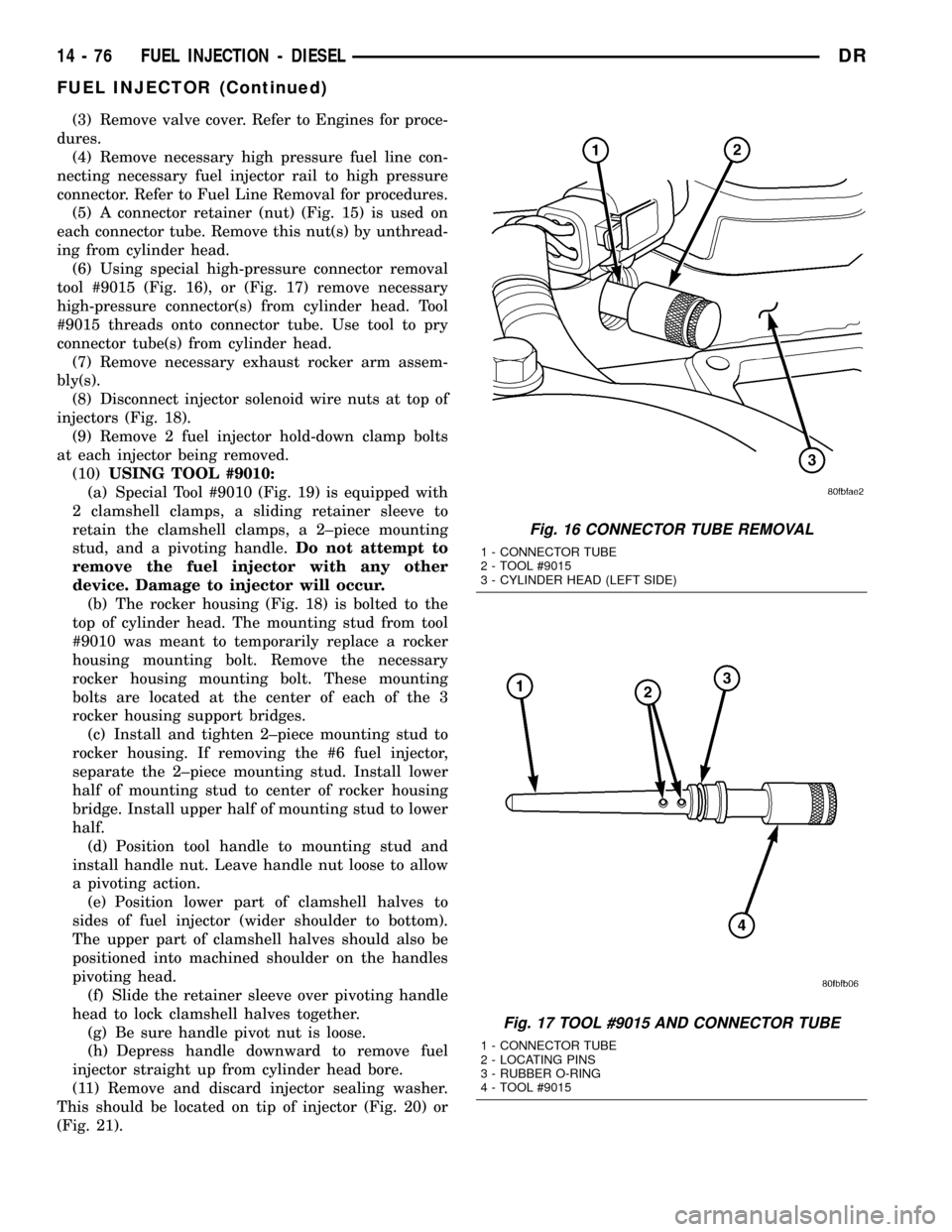
tool #9015 (Fig. 16), or (Fig. 17) remove necessary
high-pressure connector(s) from cylinder head. Tool
#9015 threads onto connector tube. Use tool to pry
connector tube(s) from cylinder head.
(7) Remove necessary exhaust rocker arm assem-
bly(s).
(8) Disconnect injector solenoid wire nuts at top of
injectors (Fig. 18).
(9) Remove 2 fuel injector hold-down clamp bolts
at each injector being removed.
(10)USING TOOL #9010:
(a) Special Tool #9010 (Fig. 19) is equipped with
2 clamshell clamps, a sliding retainer sleeve to
retain the clamshell clamps, a 2±piece mounting
stud, and a pivoting handle.Do not attempt to
remove the fuel injector with any other
device. Damage to injector will occur.
(b) The rocker housing (Fig. 18) is bolted to the
top of cylinder head. The mounting stud from tool
#9010 was meant to temporarily replace a rocker
housing mounting bolt. Remove the necessary
rocker housing mounting bolt. These mounting
bolts are located at the center of each of the 3
rocker housing support bridges.
(c) Install and tighten 2±piece mounting stud to
rocker housing. If removing the #6 fuel injector,
separate the 2±piece mounting stud. Install lower
half of mounting stud to center of rocker housing
bridge. Install upper half of mounting stud to lower
half.
(d) Position tool handle to mounting stud and
install handle nut. Leave handle nut loose to allow
a pivoting action.
(e) Position lower part of clamshell halves to
sides of fuel injector (wider shoulder to bottom).
The upper part of clamshell halves should also be
positioned into machined shoulder on the handles
pivoting head.
(f) Slide the retainer sleeve over pivoting handle
head to lock clamshell halves together.
(g) Be sure handle pivot nut is loose.
(h) Depress handle downward to remove fuel
injector straight up from cylinder head bore.
(11) Remove and discard injector sealing washer.
This should be located on tip of injector (Fig. 20) or
(Fig. 21).
Fig. 16 CONNECTOR TUBE REMOVAL
1 - CONNECTOR TUBE
2 - TOOL #9015
3 - CYLINDER HEAD (LEFT SIDE)
Fig. 17 TOOL #9015 AND CONNECTOR TUBE
1 - CONNECTOR TUBE
2 - LOCATING PINS
3 - RUBBER O-RING
4 - TOOL #9015
14 - 76 FUEL INJECTION - DIESELDR
FUEL INJECTOR (Continued)
Page 1647 of 2627

(6) Install injector into cylinder head with male
connector port facing the intake manifold. Push down
on fuel injector mounting flange to engage o-ring and
seat injector.
(7) Tightening Sequence:
(a) Install fuel injector holdown clamp (mount-
ing flange) bolts.Do a preliminary tightening
of these bolts to 5 N´m (44 in. lbs.) torque.
This preliminary tightening insures the fuel
injector is seated and centered.
(b) After tightening, relieve bolt torque, but
leave both bolts threaded in place.
(c) Install high-pressure connector and retaining
nut. Do a preliminary tightening to 15 N´m (11 ft.
lbs.) torque.
(d) Alternately tighten injector holdown bolts to
10 N´m (89 in. lbs.) torque.
(e) Do a final tightening of the high-pressure
connector and retaining nut. Tighten to 50 N´m (37
ft. lbs.) torque.
(8) Connect injector solenoid wires and nuts to top
of injectors (Fig. 18). Tighten connector nuts to 1.25
N´m (11 in. lbs.) torque.Be very careful not to
overtighten these nuts as damage to fuel injec-
tor will occur.
(9) Install exhaust rocker arm assembly. Refer to
Engine.
(10) Set exhaust valve lash. Refer to Engine.
(11) Install high pressure fuel line. Refer to Torque
Specifications.Be sure to use a secondary
back-up wrench on the connector nut (fitting)
while torquing fuel line fitting.Refer to Fuel Line
Installation for additional information.
(12) Install valve cover. Refer to Engine.
(13) Install breather assembly.
(14) Connect negative battery cables to both bat-
teries.
FUEL INJECTOR RAIL
DESCRIPTION
The fuel injector rail is bolted to the top of the
intake manifold.
OPERATION
The fuel rail is used as a distribution device to
supply high-pressure fuel to the high-pressure fuel
lines.
REMOVAL
CAUTION: Cleanliness cannot be overemphasized
when handling or replacing diesel fuel system com-
ponents. This especially includes the fuel injectors,
high-pressure fuel lines and fuel injection pump.Very tight tolerances are used with these parts. Dirt
contamination could cause rapid part wear and pos-
sible plugging of fuel injector nozzle tip holes. This
in turn could lead to possible engine misfire.
Always wash/clean any fuel system component
thoroughly before disassembly and then air dry.
Cap or cover any open part after disassembly.
Before assembly, examine each part for dirt, grease
or other contaminants and clean if necessary. When
installing new parts, lubricate them with clean
engine oil or clean diesel fuel only.
(1) Disconnect both negative battery cables at both
batteries. Isolate ends of both cables.
(2) Disconnect electrical connector at fuel pressure
sensor.
(3) Remove banjo bolt at fuel limiting valve.
(4) Disconnect necessary wiring harness retention
clips from intake manifold.
(5) Lift 2 rubber covers to gain access to positive
(+), intake heater cable nuts. Remove 2 nuts and
remove 2 cables from studs.
(6) Carefully remove 4 high-pressure fuel lines
from top of injector rail engine. Note position of each
line while removing.Do not bend lines while
removing.
CAUTION: WHEN LOOSENING OR TIGHTENING
HIGH-PRESSURE LINES ATTACHED TO A SEPA-
RATE FITTING, USE A BACK-UP WRENCH ON FIT-
TING. DO NOT ALLOW FITTING TO ROTATE.
DAMAGE TO BOTH FUEL LINE AND FITTING WILL
RESULT.
(7) Carefully remove 2 high-pressure fuel lines at
each end of injector rail. Note position of each line
while removing.Do not bend lines while remov-
ing.
(8) Remove fuel line connecting injector pump to
fuel rail.
(9) Remove 3 injector rail mounting bolts (Fig. 22).
(10) Remove rail from top of intake manifold.
INSTALLATION
(1) Clean any dirt/debris from top of intake mani-
fold and bottom of fuel rail.
(2) Position fuel rail to top of manifold and install
3 mounting bolts. Refer to Torque Specifications.
(3) Install all high-pressure lines to rail. Refer to
Fuel Lines for procedures.
(4) Reposition wiring harness to intake manifold
and install new tie wraps.
(5) Install and tighten fuel limiting valve banjo
bolt. Refer to Torque Specifications.
(6) Connect electrical connector to fuel pressure
sensor.
(7) Position 2 positive (+) cables to intake heater
studs. Install 2 nuts.
14 - 78 FUEL INJECTION - DIESELDR
FUEL INJECTOR (Continued)
Page 1675 of 2627

GEAR - LINK/COIL
TABLE OF CONTENTS
page page
GEAR - LINK/COIL
DESCRIPTION.........................20
OPERATION...........................20
REMOVAL.............................20
INSTALLATION.........................21
ADJUSTMENTS
ADJUSTMENT........................21
SPECIFICATIONS
POWER STEERING GEAR..............22
TORQUE CHART......................23
SPECIAL TOOLS
POWER STEERING GEAR..............23
PITMAN SHAFT SEAL
REMOVAL
REMOVAL - GAS ENGINE...............25REMOVAL - DIESEL...................25
INSTALLATION
INSTALLATION - GAS ENGINE...........26
INSTALLATION - DIESEL................26
STEERING GEAR INPUT SHAFT SEAL
REMOVAL.............................27
INSTALLATION.........................29
PITMAN SHAFT
REMOVAL
REMOVAL - GAS......................30
REMOVAL - DIESEL...................30
INSTALLATION
INSTALLATION - GAS..................31
INSTALLATION - DIESEL................31
GEAR - LINK/COIL
DESCRIPTION
The power steering gear is a recirculating ball type
gear (Fig. 1). The gear ratio's used are 12.5:1.
OPERATION
The gear acts as a rolling thread between the
worm shaft and rack piston. The worm shaft is sup-
ported by a thrust bearing at the lower end and a
bearing assembly at the upper end. When the worm
shaft is turned from input from the steering column
the rack piston moves. The rack piston teeth mesh
with the pitman shaft. Turning the worm shaft, turns
the pitman shaft, which turns the steering linkage.
REMOVAL
(1) Place the front wheels in a straight-ahead posi-
tion.
NOTE: The steering column on vehicles with an
automatic transmission may not be equipped with
an internal locking shaft that allows the ignition key
cylinder to be locked with the key. Alternative meth-
ods of locking the steering wheel for service will
have to be used.
(2) Lock the steering wheel.
(3) Siphon out as much power steering fluid as
possible.
Fig. 1 STEERING GEAR
1 - INPUT SHAFT
2 - OUTLET
3 - INLET
4 - VALVE ASSEMBLY HOUSING
5 - PITMAN SHAFT COVER BOLTS
6 - STEERING GEAR
7 - MESHLOAD ADJUSTER NUT
8 - PITMAN SHAFT
19 - 20 GEAR - LINK/COILDR
Page 1678 of 2627
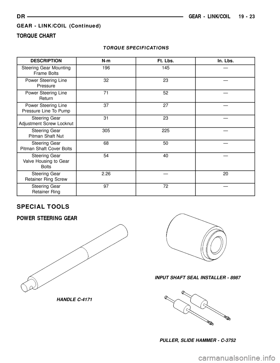
TORQUE CHART
TORQUE SPECIFICATIONS
DESCRIPTION N´m Ft. Lbs. In. Lbs.
Steering Gear Mounting
Frame Bolts196 145 Ð
Power Steering Line
Pressure32 23 Ð
Power Steering Line
Return71 52 Ð
Power Steering Line
Pressure Line To Pump37 27 Ð
Steering Gear
Adjustment Screw Locknut31 23 Ð
Steering Gear
Pitman Shaft Nut305 225 Ð
Steering Gear
Pitman Shaft Cover Bolts68 50 Ð
Steering Gear
Valve Housing to Gear
Bolts54 40 Ð
Steering Gear
Retainer Ring Screw2.26 Ð 20
Steering Gear
Retainer Ring97 72 Ð
SPECIAL TOOLS
POWER STEERING GEAR
HANDLE C-4171
INPUT SHAFT SEAL INSTALLER - 8987
PULLER, SLIDE HAMMER - C-3752
DRGEAR - LINK/COIL 19 - 23
GEAR - LINK/COIL (Continued)
Page 1685 of 2627
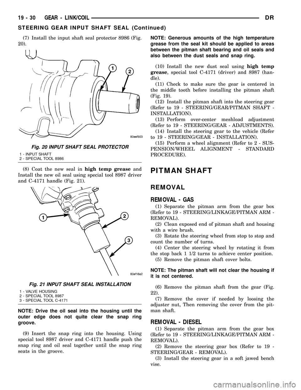
(7) Install the input shaft seal protector 8986 (Fig.
20).
(8) Coat the new seal inhigh temp greaseand
Install the new oil seal using special tool 8987 driver
and C-4171 handle (Fig. 21).
NOTE: Drive the oil seal into the housing until the
outer edge does not quite clear the snap ring
groove.
(9) Insert the snap ring into the housing. Using
special tool 8987 driver and C-4171 handle push the
snap ring and oil seal together until the snap ring
seats in the groove.NOTE: Generous amounts of the high temperature
grease from the seal kit should be applied to areas
between the pitman shaft bearing and oil seals and
also between the dust seals and snap ring.
(10) Install the new dust seal usinghigh temp
grease, special tool C-4171 (driver) and 8987 (han-
dle).
(11) Check to make sure the gear is centered in
the middle tooth before installing the pitman shaft
(Fig. 19).
(12) Install the pitman shaft into the steering gear
(Refer to 19 - STEERING/GEAR/PITMAN SHAFT -
INSTALLATION).
(13) Perform over-center meshload adjustment
(Refer to 19 - STEERING/GEAR - ADJUSTMENTS).
(14) Install the steering gear to the vehicle (Refer
to 19 - STEERING/GEAR - INSTALLATION).
(15) Perform a wheel alignment (Refer to 2 - SUS-
PENSION/WHEEL ALIGNMENT - STANDARD
PROCEDURE).
PITMAN SHAFT
REMOVAL
REMOVAL - GAS
(1) Separate the pitman arm from the gear box
(Refer to 19 - STEERING/LINKAGE/PITMAN ARM -
REMOVAL).
(2) Clean exposed end of pitman shaft and housing
with a wire brush.
(3) Rotate the steering wheel from stop to stop and
count the number of turns.
(4) Center the steering wheel by rotating it from
the stop back 1 1/2 turns to achieve center position.
(5) Remove the pitman shaft cover bolts.
NOTE: The pitman shaft will not clear the housing if
it is not centered.
(6) Remove the pitman shaft from the gear (Fig.
22).
(7) Remove the cover if needed by loosing the
adjuster nut, Then removing the cover from the pit-
man shaft.
REMOVAL - DIESEL
(1) Separate the pitman arm from the gear box
(Refer to 19 - STEERING/LINKAGE/PITMAN ARM -
REMOVAL).
(2) Remove the steering gear box (Refer to 19 -
STEERING/GEAR - REMOVAL).
(3) Install the steering gear in a soft jawed bench
vise.
Fig. 20 INPUT SHAFT SEAL PROTECTOR
1 - INPUT SHAFT
2 - SPECIAL TOOL 8986
Fig. 21 INPUT SHAFT SEAL INSTALLATION
1 - VALVE HOUSING
2 - SPECIAL TOOL 8987
3 - SPECIAL TOOL C-4171
19 - 30 GEAR - LINK/COILDR
STEERING GEAR INPUT SHAFT SEAL (Continued)
Page 1861 of 2627
STANDARD PROCEDURE - ALUMINUM
THREAD REPAIR
Damaged or worn threads in the aluminum trans-
mission case and valve body can be repaired by the
use of Heli-CoilsŸ, or equivalent. This repair con-
sists of drilling out the worn-out damaged threads.
Then tap the hole with a special Heli-CoilŸ tap, or
equivalent, and installing a Heli-CoilŸ insert, or
equivalent, into the hole. This brings the hole back to
its original thread size.
Heli-CoilŸ, or equivalent, tools and inserts are
readily available from most automotive parts suppli-
ers.
REMOVAL
NOTE: The overdrive unit can be removed and ser-
viced separately. It is not necessary to remove the
entire transmission assembly to perform overdrive
unit repairs.
(1) Disconnect battery negative cable.
(2) Raise vehicle.
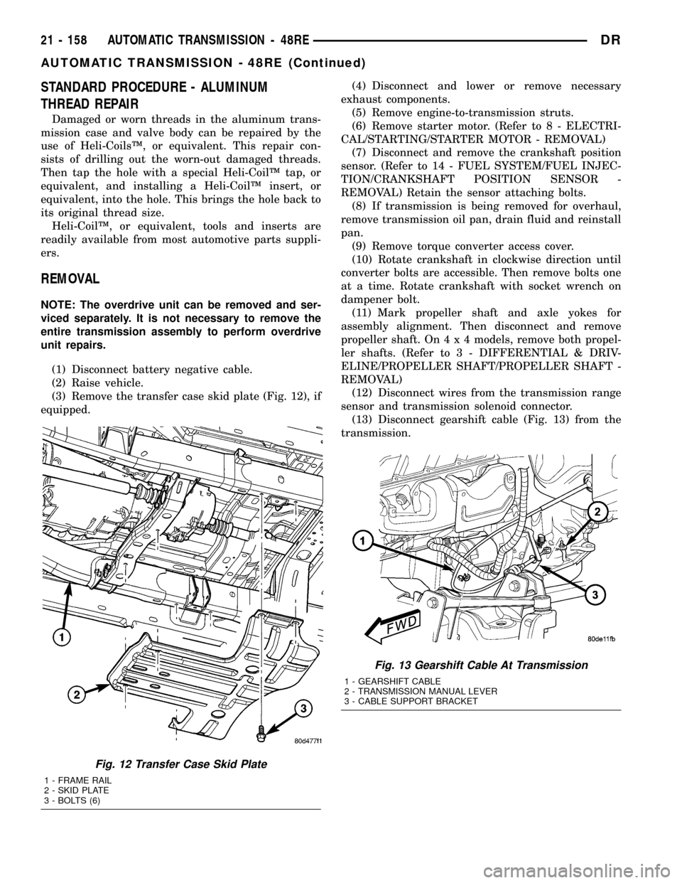
(3) Remove the transfer case skid plate (Fig. 12), if
equipped.(4) Disconnect and lower or remove necessary
exhaust components.
(5) Remove engine-to-transmission struts.
(6) Remove starter motor. (Refer to 8 - ELECTRI-
CAL/STARTING/STARTER MOTOR - REMOVAL)
(7) Disconnect and remove the crankshaft position
sensor. (Refer to 14 - FUEL SYSTEM/FUEL INJEC-
TION/CRANKSHAFT POSITION SENSOR -
REMOVAL) Retain the sensor attaching bolts.
(8) If transmission is being removed for overhaul,
remove transmission oil pan, drain fluid and reinstall
pan.
(9) Remove torque converter access cover.
(10) Rotate crankshaft in clockwise direction until
converter bolts are accessible. Then remove bolts one
at a time. Rotate crankshaft with socket wrench on
dampener bolt.
(11) Mark propeller shaft and axle yokes for
assembly alignment. Then disconnect and remove
propeller shaft. On4x4models, remove both propel-
ler shafts. (Refer to 3 - DIFFERENTIAL & DRIV-
ELINE/PROPELLER SHAFT/PROPELLER SHAFT -
REMOVAL)
(12) Disconnect wires from the transmission range
sensor and transmission solenoid connector.
(13) Disconnect gearshift cable (Fig. 13) from the
transmission.
Fig. 12 Transfer Case Skid Plate
1 - FRAME RAIL
2 - SKID PLATE
3 - BOLTS (6)
Fig. 13 Gearshift Cable At Transmission
1 - GEARSHIFT CABLE
2 - TRANSMISSION MANUAL LEVER
3 - CABLE SUPPORT BRACKET
21 - 158 AUTOMATIC TRANSMISSION - 48REDR
AUTOMATIC TRANSMISSION - 48RE (Continued)
Page 1878 of 2627
(13) Install bolts attaching converter housing to
engine.
(14) Install rear support.
(15) Install the rear transmission crossmember.
(16) Lower transmission onto crossmember and
install bolts attaching transmission mount to cross-
member.
(17) Remove engine support fixture.
(18) Install the transfer case, if equipped.
(19) Install crankshaft position sensor. (Refer to 14
- FUEL SYSTEM/FUEL INJECTION/CRANKSHAFT
POSITION SENSOR - INSTALLATION)
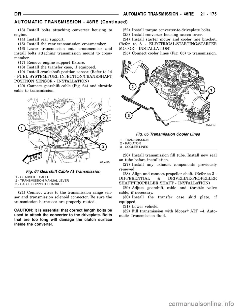
(20) Connect gearshift cable (Fig. 64) and throttle
cable to transmission.
(21) Connect wires to the transmission range sen-
sor and transmission solenoid connector. Be sure the
transmission harnesses are properly routed.
CAUTION: It is essential that correct length bolts be
used to attach the converter to the driveplate. Bolts
that are too long will damage the clutch surface
inside the converter.(22) Install torque converter-to-driveplate bolts.
(23) Install converter housing access cover.
(24) Install starter motor and cooler line bracket.
(Refer to 8 - ELECTRICAL/STARTING/STARTER
MOTOR - INSTALLATION)
(25) Connect cooler lines (Fig. 65) to transmission.
(26) Install transmission fill tube. Install new seal
on tube before installation.
(27) Install any exhaust components previously
removed.
(28) Align and connect propeller shaft. (Refer to 3 -
DIFFERENTIAL & DRIVELINE/PROPELLER
SHAFT/PROPELLER SHAFT - INSTALLATION)
(29) Adjust gearshift cable and throttle valve
cable, if necessary.
(30) Install the transfer case skid plate, if
equipped.
(31) Lower vehicle.
(32) Fill transmission with MopartATF +4, Auto-
matic Transmission fluid.
Fig. 64 Gearshift Cable At Transmission
1 - GEARSHIFT CABLE
2 - TRANSMISSION MANUAL LEVER
3 - CABLE SUPPORT BRACKET
Fig. 65 Transmission Cooler Lines
1 - TRANSMISSION
2 - RADIATOR
3 - COOLER LINES
DRAUTOMATIC TRANSMISSION - 48RE 21 - 175
AUTOMATIC TRANSMISSION - 48RE (Continued)
Page 1896 of 2627
ACCUMULATOR
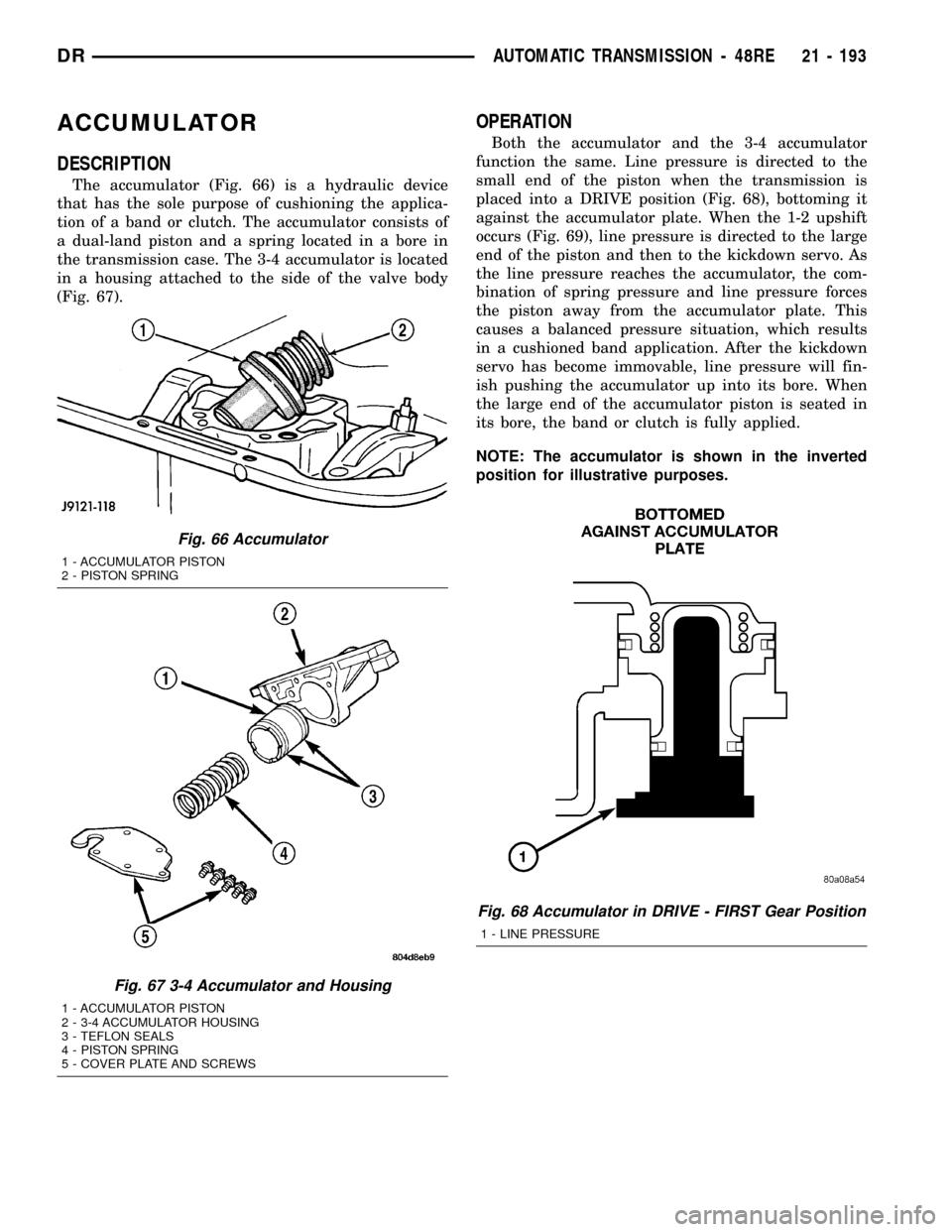
DESCRIPTION
The accumulator (Fig. 66) is a hydraulic device
that has the sole purpose of cushioning the applica-
tion of a band or clutch. The accumulator consists of
a dual-land piston and a spring located in a bore in
the transmission case. The 3-4 accumulator is located
in a housing attached to the side of the valve body
(Fig. 67).
OPERATION
Both the accumulator and the 3-4 accumulator
function the same. Line pressure is directed to the
small end of the piston when the transmission is
placed into a DRIVE position (Fig. 68), bottoming it
against the accumulator plate. When the 1-2 upshift
occurs (Fig. 69), line pressure is directed to the large
end of the piston and then to the kickdown servo. As
the line pressure reaches the accumulator, the com-
bination of spring pressure and line pressure forces
the piston away from the accumulator plate. This
causes a balanced pressure situation, which results
in a cushioned band application. After the kickdown
servo has become immovable, line pressure will fin-
ish pushing the accumulator up into its bore. When
the large end of the accumulator piston is seated in
its bore, the band or clutch is fully applied.
NOTE: The accumulator is shown in the inverted
position for illustrative purposes.
Fig. 66 Accumulator
1 - ACCUMULATOR PISTON
2 - PISTON SPRING
Fig. 67 3-4 Accumulator and Housing
1 - ACCUMULATOR PISTON
2 - 3-4 ACCUMULATOR HOUSING
3 - TEFLON SEALS
4 - PISTON SPRING
5 - COVER PLATE AND SCREWS
Fig. 68 Accumulator in DRIVE - FIRST Gear Position
1 - LINE PRESSURE
DRAUTOMATIC TRANSMISSION - 48RE 21 - 193