1998 DODGE RAM 1500 Valve cover
[x] Cancel search: Valve coverPage 1435 of 2627
(5) Piston installation into the cylinder bore
requires slightly more pressure than that required
for non-coated pistons. The bonded coating on the
piston will give the appearance of a line-to-line fit
with the cylinder bore.
REMOVAL
(1) Disconnect negative cable from battery.
(2) Remove the following components:
²Oil pan and gasket/windage tray (Refer to 9 -
ENGINE/LUBRICATION/OIL PAN - REMOVAL).
²Cylinder head covers (Refer to 9 - ENGINE/
CYLINDER HEAD/CYLINDER HEAD COVER(S) -
REMOVAL) and (Refer to 9 - ENGINE/CYLINDER
HEAD/CYLINDER HEAD COVER(S) - REMOVAL).
²Timing chain cover (Refer to 9 - ENGINE/
VALVE TIMING/TIMING BELT / CHAIN COVER(S)
- REMOVAL).
²Cylinder head(s) (Refer to 9 - ENGINE/CYLIN-
DER HEAD - REMOVAL) and (Refer to 9 - ENGINE/
CYLINDER HEAD - REMOVAL).
(3) If necessary, remove top ridge of cylinder bores
with a reliable ridge reamer before removing pistons
from cylinder block.Be sure to keep tops of pis-
tons covered during this operation.Pistons and
connecting rods must be removed from top of cylinder
block. When removing piston and connecting rod
assemblies from the engine, rotate crankshaft so the
each connecting rod is centered in cylinder bore.CAUTION: DO NOT use a number stamp or a punch
to mark connecting rods or caps, as damage to
connecting rods could occur
NOTE: Connecting rods and bearing caps are not
interchangeable and should be marked before
removing to ensure correct reassembly.
(4)
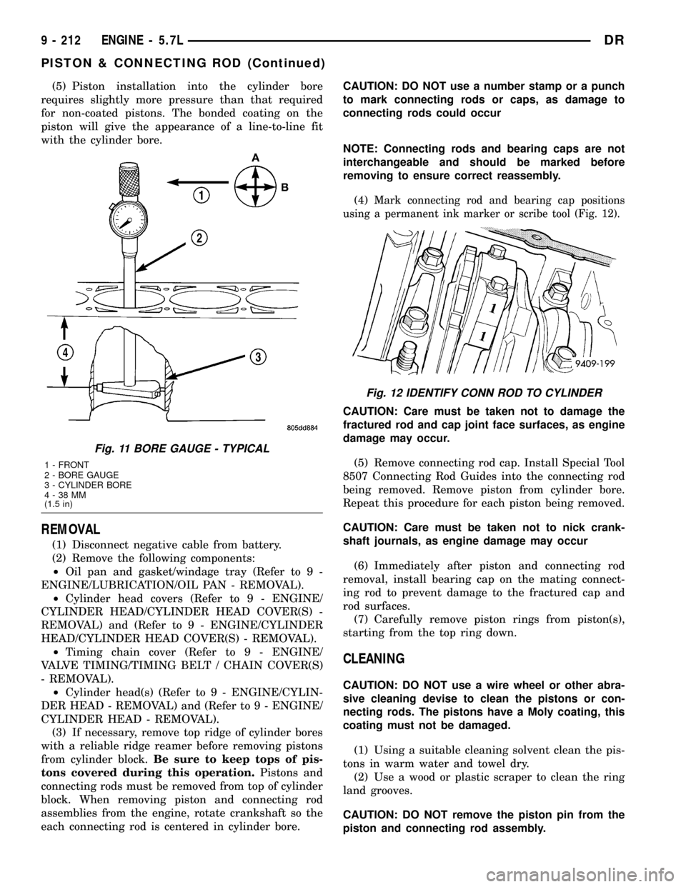
Mark connecting rod and bearing cap positions
using a permanent ink marker or scribe tool (Fig. 12).
CAUTION: Care must be taken not to damage the
fractured rod and cap joint face surfaces, as engine
damage may occur.
(5) Remove connecting rod cap. Install Special Tool
8507 Connecting Rod Guides into the connecting rod
being removed. Remove piston from cylinder bore.
Repeat this procedure for each piston being removed.
CAUTION: Care must be taken not to nick crank-
shaft journals, as engine damage may occur
(6) Immediately after piston and connecting rod
removal, install bearing cap on the mating connect-
ing rod to prevent damage to the fractured cap and
rod surfaces.
(7) Carefully remove piston rings from piston(s),
starting from the top ring down.
CLEANING
CAUTION: DO NOT use a wire wheel or other abra-
sive cleaning devise to clean the pistons or con-
necting rods. The pistons have a Moly coating, this
coating must not be damaged.
(1) Using a suitable cleaning solvent clean the pis-
tons in warm water and towel dry.
(2) Use a wood or plastic scraper to clean the ring
land grooves.
CAUTION: DO NOT remove the piston pin from the
piston and connecting rod assembly.
Fig. 11 BORE GAUGE - TYPICAL
1 - FRONT
2 - BORE GAUGE
3 - CYLINDER BORE
4-38MM
(1.5 in)
Fig. 12 IDENTIFY CONN ROD TO CYLINDER
9 - 212 ENGINE - 5.7LDR
PISTON & CONNECTING ROD (Continued)
Page 1447 of 2627
OIL PAN
REMOVAL
(1) Disconnect the negative battery cable.
(2) Install engine support fixture special tool #
8534.Do not raise engine at this time.
(3) Loosen both left and right side engine mount
through bolts. Do not remove bolts.
(4) Remove the structural dust cover, if equipped.
(5) Drain engine oil.
(6) Remove the front crossmember(Refer to 13 -
FRAME & BUMPERS/FRAME/FRONT CROSS-
MEMBER - REMOVAL).
CAUTION: Only raise the engine enough to provide
clearance for oil pan removal. Check for proper
clearance at fan shroud to fan and cowl to intake
manifold.
(7) Raise engine using special tool # 8534 to pro-
vide clearance to remove oil pan.
NOTE: Do not pry on oil pan or oil pan gasket. Gas-
ket is integral to engine windage tray and does not
come out with oil pan.
(8) Remove the oil pan mounting bolts and oil pan.
NOTE: The double ended oil pan studs must be
installed in the same location that they were
removed from.
(9) Unbolt oil pump pickup tube and remove tube.
(10) Inspect the integral windage tray and gasket
and replace as needed.
INSTALLATION
(1) Clean the oil pan gasket mating surface of the
block and oil pan.
(2) Inspect the integral windage tray and gasket
and replace as needed.
(3) Reinstall the oil pump pickup tube with new
o-ring. Tighten tube to pump fasteners to 28 N´m
(250 in. lbs.).
NOTE: The double ended oil pan studs must be
installed in the same location that they were
removed from.
(4) Position the oil pan and install the mounting
bolts and studs.. Tighten the mounting bolts to 12
N´m (105 in.lbs.).
(5) Lower the engine into mounts using special
tool # 8534.
(6) Install both the left and right side engine
mount through bolts. Tighten the nuts to 68 N´m (50
ft. lbs.).(7) Remove special tool # 8534.
(8) Install structural dust cover, if equipped.
(9) Install the front crossmember(Refer to 13 -
FRAME & BUMPERS/FRAME/FRONT CROSS-
MEMBER - INSTALLATION).
(10) Fill engine oil.
(11) Reconnect the negative battery cable.
(12) Start engine and check for leaks.
OIL PUMP
REMOVAL
(1) Remove the oil pan and pick-up tube(Refer to 9
- ENGINE/LUBRICATION/OIL PAN - REMOVAL).
(2) Remove the timing chain cover(Refer to 9 -
ENGINE/VALVE TIMING/TIMING BELT / CHAIN
COVER(S) - REMOVAL).
(3) Remove the four bolts, and the oil pump.
CLEANING
(1) Wash all parts in a suitable solvent.
INSPECTION
CAUTION: Oil pump pressure relief valve and
spring should not be removed from the oil pump. If
these components are disassembled and or
removed from the pump the entire oil pump assem-
bly must be replaced.
(1) Remove the pump cover.
(2) Clean all parts thoroughly. Mating surface of
the oil pump housing should be smooth. If the pump
cover is scratched or grooved the oil pump assembly
should be replaced.
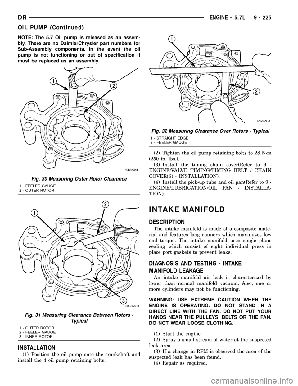
(3) Slide outer rotor into the body of the oil pump.
Press the outer rotor to one side of the oil pump body
and measure clearance between the outer rotor and
the body (Fig. 30). If the measurement is 0.235mm
(0.009 in.) or more the oil pump assembly must be
replaced.
(4) Install the inner rotor in the into the oil pump
body. Measure the clearance between the inner and
outer rotors (Fig. 31). If the clearance between the
rotors is .150 mm (0.006 in.) or more the oil pump
assembly must be replaced.
(5) Place a straight edge across the body of the oil
pump (between the bolt holes), if a feeler gauge of
.095 mm (0.0038 in.) or greater can be inserted
between the straightedge and the rotors, the pump
must be replaced (Fig. 32).
(6) Reinstall the pump cover. Torque fasteners to
15 N´m (132 in. lbs.).
9 - 224 ENGINE - 5.7LDR
Page 1448 of 2627
NOTE: The 5.7 Oil pump is released as an assem-
bly. There are no DaimlerChrysler part numbers for
Sub-Assembly components. In the event the oil
pump is not functioning or out of specification it
must be replaced as an assembly.
INSTALLATION
(1) Position the oil pump onto the crankshaft and
install the 4 oil pump retaining bolts.(2) Tighten the oil pump retaining bolts to 28 N´m
(250 in. lbs.).
(3) Install the timing chain cover(Refer to 9 -
ENGINE/VALVE TIMING/TIMING BELT / CHAIN
COVER(S) - INSTALLATION).
(4) Install the pick-up tube and oil pan(Refer to 9 -
ENGINE/LUBRICATION/OIL PAN - INSTALLA-
TION).
INTAKE MANIFOLD
DESCRIPTION
The intake manifold is made of a composite mate-
rial and features long runners which maximizes low
end torque. The intake manifold uses single plane
sealing which consist of eight individual press in
place port gaskets to prevent leaks.
DIAGNOSIS AND TESTING - INTAKE
MANIFOLD LEAKAGE
An intake manifold air leak is characterized by
lower than normal manifold vacuum. Also, one or
more cylinders may not be functioning.
WARNING: USE EXTREME CAUTION WHEN THE
ENGINE IS OPERATING. DO NOT STAND IN A
DIRECT LINE WITH THE FAN. DO NOT PUT YOUR
HANDS NEAR THE PULLEYS, BELTS OR THE FAN.
DO NOT WEAR LOOSE CLOTHING.
(1) Start the engine.
(2) Spray a small stream of water at the suspected
leak area.
(3) If a change in RPM is observed the area of the
suspected leak has been found.
(4) Repair as required.
Fig. 30 Measuring Outer Rotor Clearance
1 - FEELER GAUGE
2 - OUTER ROTOR
Fig. 31 Measuring Clearance Between Rotors -
Typical
1 - OUTER ROTOR
2 - FEELER GAUGE
3 - INNER ROTOR
Fig. 32 Measuring Clearance Over Rotors - Typical
1 - STRAIGHT EDGE
2 - FEELER GAUGE
DRENGINE - 5.7L 9 - 225
OIL PUMP (Continued)
Page 1452 of 2627
(7) Install the camshaft bolt. Tighten the bolt to
122 N´m (90 ft. lbs.) torque.
(8)Remove tensioner pin.Again, verify align-
ment of timing marks.
(9) Install the oil pump(Refer to 9 - ENGINE/LU-
BRICATION/OIL PUMP - INSTALLATION).
(10) Install the oil pan and pick up(Refer to 9 -
ENGINE/LUBRICATION/OIL PAN - INSTALLA-
TION).
(11) Install the timing chain cover(Refer to 9 -
ENGINE/VALVE TIMING/TIMING BELT / CHAIN
COVER(S) - INSTALLATION).
(12) Fill cooling system(Refer to 7 - COOLING -
STANDARD PROCEDURE).
(13) Connect battery negative cable.
(14) Start engine and check for oil and coolant
leaks.TIMING CHAIN/TENSIONER
DESCRIPTION
The timing chain tensioner is a stamped steel con-
stant tension mechanical design. It is mounted to the
front of the engine, behind the timing chain drive.
OPERATION
The timing chain tension is maintained by routing
the timing chain through the tensioner assembly. A
nylon covered spring steel arm presses on the timing
chain maintaining the correct chain tension.
DRENGINE - 5.7L 9 - 229
TIMING/CHAIN AND SPROCKETS (Continued)
Page 1453 of 2627
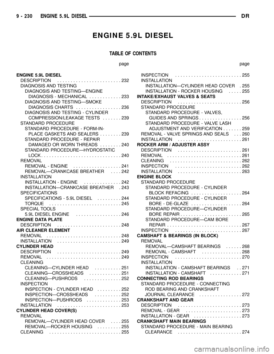
ENGINE 5.9L DIESEL
TABLE OF CONTENTS
page page
ENGINE 5.9L DIESEL
DESCRIPTION........................232
DIAGNOSIS AND TESTING
DIAGNOSIS AND TESTINGÐENGINE
DIAGNOSIS - MECHANICAL............233
DIAGNOSIS AND TESTINGÐSMOKE
DIAGNOSIS CHARTS.................236
DIAGNOSIS AND TESTING - CYLINDER
COMPRESSION/LEAKAGE TESTS.......239
STANDARD PROCEDURE
STANDARD PROCEDURE - FORM-IN-
PLACE GASKETS AND SEALERS........239
STANDARD PROCEDURE - REPAIR
DAMAGED OR WORN THREADS........240
STANDARD PROCEDUREÐHYDROSTATIC
LOCK..............................240
REMOVAL
REMOVAL - ENGINE..................241
REMOVALÐCRANKCASE BREATHER....242
INSTALLATION
INSTALLATION - ENGINE..............242
INSTALLATIONÐCRANKCASE BREATHER . 243
SPECIFICATIONS
SPECIFICATIONS - 5.9L DIESEL.........244
TORQUE...........................245
SPECIAL TOOLS
5.9L DIESEL ENGINE.................246
ENGINE DATA PLATE
DESCRIPTION........................248
AIR CLEANER ELEMENT
REMOVAL............................248
INSTALLATION........................249
CYLINDER HEAD
DESCRIPTION........................249
REMOVAL............................249
CLEANING
CLEANINGÐCYLINDER HEAD..........251
CLEANINGÐCROSSHEADS............251
CLEANINGÐPUSHRODS..............252
INSPECTION
INSPECTION - CYLINDER HEAD.........252
INSPECTIONÐCROSSHEADS..........252
INSPECTIONÐPUSHRODS.............253
INSTALLATION........................253
CYLINDER HEAD COVER(S)
REMOVAL
REMOVALÐCYLINDER HEAD COVER....255
REMOVALÐROCKER HOUSING.........255
CLEANING...........................255INSPECTION.........................255
INSTALLATION
INSTALLATIONÐCYLINDER HEAD COVER . 255
INSTALLATION - ROCKER HOUSING.....255
INTAKE/EXHAUST VALVES & SEATS
DESCRIPTION........................256
STANDARD PROCEDURE
STANDARD PROCEDURE - VALVES,
GUIDES AND SPRINGS................256
STANDARD PROCEDURE - VALVE LASH
ADJUSTMENT AND VERIFICATION.......259
REMOVAL - VALVE SPRINGS AND SEALS . . . 260
INSTALLATION........................261
ROCKER ARM / ADJUSTER ASSY
DESCRIPTION........................261
REMOVAL............................261
CLEANING...........................262
INSPECTION.........................262
INSTALLATION........................263
ENGINE BLOCK
STANDARD PROCEDURE
STANDARD PROCEDURE - CYLINDER
BLOCK REFACING...................264
STANDARD PROCEDURE - CYLINDER
BORE - DE-GLAZE...................264
STANDARD PROCEDUREÐCYLINDER
BORE REPAIR.......................265
STANDARD PROCEDUREÐCAM BORE
REPAIR ............................267
INSPECTION.........................267
CAMSHAFT & BEARINGS (IN BLOCK)
REMOVAL
REMOVALÐCAMSHAFT BEARINGS......268
REMOVAL - CAMSHAFT...............268
INSPECTION.........................270
INSTALLATION
INSTALLATION - CAMSHAFT BEARINGS . . 271
INSTALLATION - CAMSHAFT............271
CONNECTING ROD BEARINGS
STANDARD PROCEDURE - CONNECTING
ROD BEARING AND CRANKSHAFT
JOURNAL CLEARANCE................272
CRANKSHAFT AND GEAR
DESCRIPTION........................273
REMOVAL - GEAR.....................273
INSTALLATION - GEAR..................273
CRANKSHAFT MAIN BEARINGS
STANDARD PROCEDURE - MAIN BEARING
CLEARANCE........................274
9 - 230 ENGINE 5.9L DIESELDR
Page 1454 of 2627
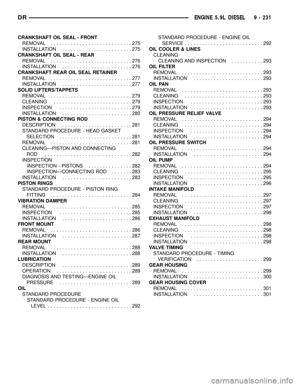
CRANKSHAFT OIL SEAL - FRONT
REMOVAL............................275
INSTALLATION........................275
CRANKSHAFT OIL SEAL - REAR
REMOVAL............................276
INSTALLATION........................276
CRANKSHAFT REAR OIL SEAL RETAINER
REMOVAL............................277
INSTALLATION........................277
SOLID LIFTERS/TAPPETS
REMOVAL............................279
CLEANING...........................279
INSPECTION.........................279
INSTALLATION........................280
PISTON & CONNECTING ROD
DESCRIPTION........................281
STANDARD PROCEDURE - HEAD GASKET
SELECTION.........................281
REMOVAL............................281
CLEANINGÐPISTON AND CONNECTING
ROD ..............................282
INSPECTION
INSPECTION - PISTONS...............282
INSPECTIONÐCONNECTING ROD.......283
INSTALLATION........................283
PISTON RINGS
STANDARD PROCEDURE - PISTON RING
FITTING............................284
VIBRATION DAMPER
REMOVAL............................285
INSPECTION.........................285
INSTALLATION........................286
FRONT MOUNT
REMOVAL............................286
INSTALLATION........................287
REAR MOUNT
REMOVAL............................288
INSTALLATION........................288
LUBRICATION
DESCRIPTION........................289
OPERATION..........................289
DIAGNOSIS AND TESTINGÐENGINE OIL
PRESSURE.........................289
OIL
STANDARD PROCEDURE
STANDARD PROCEDURE - ENGINE OIL
LEVEL.............................292STANDARD PROCEDURE - ENGINE OIL
SERVICE...........................292
OIL COOLER & LINES
CLEANING
CLEANING AND INSPECTION...........293
OIL FILTER
REMOVAL............................293
INSTALLATION........................293
OIL PAN
REMOVAL............................293
CLEANING...........................293
INSPECTION.........................293
INSTALLATION........................293
OIL PRESSURE RELIEF VALVE
REMOVAL............................294
CLEANING...........................294
INSPECTION.........................294
INSTALLATION........................294
OIL PRESSURE SWITCH
REMOVAL............................294
INSTALLATION........................294
OIL PUMP
REMOVAL............................294
CLEANING...........................295
INSPECTION.........................295
INSTALLATION........................296
INTAKE MANIFOLD
REMOVAL............................297
CLEANING...........................297
INSPECTION.........................297
INSTALLATION........................298
EXHAUST MANIFOLD
REMOVAL............................298
CLEANING...........................298
INSPECTION.........................298
INSTALLATION........................298
VALVE TIMING
STANDARD PROCEDURE - TIMING
VERIFICATION.......................299
GEAR HOUSING
REMOVAL............................299
INSTALLATION........................300
GEAR HOUSING COVER
REMOVAL............................301
INSTALLATION........................301
DRENGINE 5.9L DIESEL 9 - 231
Page 1462 of 2627
DIAGNOSIS AND TESTING - CYLINDER
COMPRESSION/LEAKAGE TESTS
CYLINDER COMPRESSION PRESSURE
The results of a cylinder compression pressure test
can be utilized to diagnose several engine malfunc-
tions.
Ensure batteries are completely charged and the
engine starter motor is in good operating condition.
Otherwise, the indicated compression pressures may
not be valid for diagnostic purposes.
(1) Disconnect the fuel inlet line to the fuel trans-
fer pump. Plug the fuel line from the fuel tank.
(2) Start the engine and idle until the engine stalls
(runs out of fuel).
(3) Disconnect all three injector wire harness con-
nectors at the rocker housing.
(4) Remove the breather cover and cylinder head
cover.
(5) Remove the high pressure fuel line between the
cylinder head and fuel rail for the cylinder to be
tested. Use tool# 9011 to cap this fuel rail on the cyl-
inder being tested.
(6) Remove the exhaust rocker lever.
(7) Use Tool 9010 to remove the injector and cop-
per sealing washer.
(8) Install the exhaust rocker lever and torque to
36 N´m (27 ft. lbs.).
(9) Cover the remaining rocker levers with clean
shop towels to prevent any oil splatter under the
hood.
(10) Place a rag over the compression test tool fit-
ting. Crank the engine for 2±3 seconds to purge any
fuel that may have drained into the cylinder when
the injector was removed.
(11) Connect the compression test gauge.
(12) Crank the engine for 5 seconds and record the
pressure reading. Repeat this step three times and
calculate the average of the three readings.
NOTE: The minimum cylinder pressure is 350 psi.
Cylinder pressure should be within 20% from cylin-
der to cylinder.
(13) Combustion pressure leakage can be checked
if cylinder pressure is below the specification. Per-
form the leakage test procedure on each cylinder
according to the tester manufacturer instructions.
(14) Upon completion of the test check an erase
any engine related fault codes.
CYLINDER COMBUSTION PRESSURE LEAKAGE
The combustion pressure leakage test provides an
accurate means for determining engine condition.
Combustion pressure leakage testing will detect:²Exhaust and intake valve leaks (improper seat-
ing).
²Leaks between adjacent cylinders or into water
jacket.
²Any causes for combustion/compression pressure
loss
(1) Start and operate the engine until it attains
normal operating temperature.
(2) Remove the breather cover and cylinder head
cover.
(3) Disconnect all three injector wire harness con-
nectors at the rocker housing.
(4) Bring the cylinder to be tested to TDC.
(5) Remove the high pressure fuel line between the
cylinder head and the fuel rail for the cylinder to be
tested.
(6) Install capping Tool 9011 onto the rail.
(7) Remove the high pressure connector nut and
high pressure connector with Tool 9015.
(8) Remove the exhaust and intake rocker lever.
(9) Use Tool 9010 to remove the injector and cop-
per sealing washer.
(10) Install compression test Tool 9007 into the
injector bore.
(11) Connect the leakage tester and perform the
leakage test procedure on each cylinder according to
the tester manufacturer's instructions.
(12) Upon completion of the test check and erase
any engine related fault codes.
STANDARD PROCEDURE
STANDARD PROCEDURE - FORM-IN-PLACE
GASKETS AND SEALERS
There are numerous places where form-in-place
gaskets are used on the engine. Care must be taken
when applying form-in-place gaskets to assure
obtaining the desired results.Do not use form-in-
place gasket material unless specified.Bead size,
continuity, and location are of great importance. Too
thin a bead can result in leakage while too much can
result in spill-over which can break off and obstruct
fluid feed lines. A continuous bead of the proper
width is essential to obtain a leak-free gasket.
There are numerous types of form-in-place gasket
materials that are used in the engine area. Mopart
Engine RTV GEN II, MopartATF-RTV, and Mopart
Gasket Maker gasket materials, each have different
properties and can not be used in place of the other.
MOPARtENGINE RTV GEN II
MopartEngine RTV GEN II is used to seal com-
ponents exposed to engine oil. This material is a spe-
cially designed black silicone rubber RTV that
retains adhesion and sealing properties when
exposed to engine oil. Moisture in the air causes the
DRENGINE 5.9L DIESEL 9 - 239
ENGINE 5.9L DIESEL (Continued)
Page 1466 of 2627
(8) Replace injector o-ring and sealing washer on
injectors #5 and #6. Install injectors and torque using
the following steps:
²Step 1ÐInstall injector hold-down capscrews
and torque to 5 N´m (44 in. lbs.) torque.
²Step 2ÐLoosen injector hold-down capscrews.
²Step 3ÐInstall HPC connector tube and nut.
Torque nut to 15 N´m (11 ft. lbs.) torque.
²Step 4ÐTorque injector hold-down capscrews to
10 N´m (89 in. lbs.) torque.
²Step 5ÐTorque HPC connector tube nut to 50
N´m (37 ft. lbs.) torque.
(9) Install #5 and #6 high pressure fuel lines. Fol-
low correct torque sequence per section 14. Torque
fuel line fittings to 30 N-m (22 ft-lb). Torque brace
capscrew to 24 N-m (18 ft-lb).
(10) Install rear engine lift bracket. Torque to 77
N-m (57 ft-lb).
(11) Install push tubes, rocker arms, and pedestals
for cylinders #4, #5, and #6. Torque the mounting
bolts to 36 N-m (27 ft-lbs).
(12) Reset valve lash on cylinders #4, #5, and #6.
Torque adjusting nuts to 24 N-m (18 ft-lbs).
(13) Install cylinder head cover. Torque to 24 N-m
(18 ft-lbs).(Refer to 9 - ENGINE/CYLINDER HEAD -
INSTALLATION).
(14) Connect breather tube and lube oil drain tube
to breather housing cover. Install breather housing.
Torque capscrews to 24 N-m (18 ft-lbs)
(15) Connect fuel supply and return hoses.
(16) Connect ECM ground to hydroform screw.
Connect ECM power connector.
(17) Install the APPS cable(s) to the APPS. Install
the throttle linkage cover.
(18) Install the power steering pump.
(19) Install the damper and speed indicator ring.
Torque to 40 N-m (30 ft-lb) plus 60 degrees.
(20) Connect the engine block heater connection.
(21) Connect the A/C compressor and pressure sen-
sor connectors
(22) Install the charge air cooler and a/c condenser
(if equipped). Install and tighten the charge air
cooler mounting bolts to 2 N-m (17 in-lbs).
(23) Connect the charge air cooler piping. Torque
all clamps to 8 N-m (72 in-lbs).
(24) Connect the a/c refrigerant lines to the a/c
condenser (if equipped).
(25) Install the radiator upper support panel.
(26) Install radiator.
(27) Connect the transmission quick-connect oil
cooler lines.(28) Raise vehicle.
(29) Connect a/c compressor suction/discharge hose
(if equipped).
(30) Install the radiator lower hose and clamps.
(31) Install the battery negative cables to the
engine block on the driver and passenger side.
(32) Install the transmission adapter with a new
camshaft rectangular ring seal. Torque to 77 N-m (57
ft-lb).
(33) Install the flywheel/flexplate. Torque to 137
N-m (101 ft-lb).
(34) Install the starter motor. Torque to 43 N-m
(32 ft-lb). (Refer to 8 - ELECTRICAL/STARTING/
STARTER MOTOR - INSTALLATION).
(35) Connect engine to vehicle harness connectors.
(36) Install transmission and transfer case (if
equipped).
(37) Connect the exhaust pipe to the turbocharger
elbow.
(38) Connect the transmission auxiliary oil cooler
lines (if equipped).
(39) Lower the vehicle.
(40) Connect the heater core supply and return
hoses.
(41) Install the cooling fan and upper fan shroud
at the same time. (Refer to 7 - COOLING/ENGINE/
RADIATOR FAN - INSTALLATION).
(42) Install the coolant recovery bottle.
(43) Install the windshield washer bottle.
(44) Install the upper radiator hose and clamps.
(45) Raise vehicle.
(46) Connect electronically controlled fan drive
wire harness. Install lower radiator fan shroud.
(47) Change oil filter and install new engine oil.
(48) Fill the cooling system with coolant. (Refer to
7 - COOLING - STANDARD PROCEDURE).
(49) Connect grid heater harness at grid heater
relays.
(50) Connect electrical connections to rear of alter-
nator.
(51) Start the engine and inspect for engine oil,
coolant, and fuel leaks.
INSTALLATIONÐCRANKCASE BREATHER
(1) Install a new o-ring onto the breather element.
(2) Lubricate o-ring and install into cylinder head
cover. Torque capscrews to 10 N´m (89 in. lbs.).
(3) Connect breather tube and lube oil drain tube.
(4) Install breather cover (Fig. 4). Torque to 24
N´m (18 ft. lbs.)
(5) Install oil fill cap.
DRENGINE 5.9L DIESEL 9 - 243
ENGINE 5.9L DIESEL (Continued)