1998 DODGE RAM 1500 Locks
[x] Cancel search: LocksPage 1805 of 2627

(3) Remove first gear blocker rings (2) and cones
from the 1-2 synchro assembly (Fig. 39).
(4) Install the remainder of the output shaft into
Fixture 8227 with press blocks under second gear.
(5) Install shaft and Fixture assembly into a shop
press (Fig. 40).
(6) Press second gear, 1-2 synchro assembly and
first gear bearing sleeve from the output shaft.
(7) Remove second gear bearing from the output
shaft.(8) Reverse output shaft in the Fixture 8227 with
press blocks positioned under the 5-6 synchro assem-
bly.
(9) Press the 5-6 synchro assembly from the out-
put shaft.
Fig. 39 FIRST GEAR BLOCKER RINGS AND
FRICTION CONE
1 - OUTPUT SHAFT
2 - FIRST GEAR BLOCKER RINGS
3 - FIRST GEAR FRICTION CONE
Fig. 40 SECOND GEAR, 1-2 SYNCHRO & FIRST
GEAR BEARING SLEEVE
1 - OUTPUT SHAFT
2 - FIRST GEAR BEARING SLEEVE
3 - SECOND GEAR
4 - FIXTURE
5 - 1-2 SYNCHRO
21 - 102 MANUAL TRANSMISSION - NV5600DR
MANUAL TRANSMISSION - NV5600 (Continued)
Page 1806 of 2627

(10) Remove sixth gear and the sixth gear bearing
from the output shaft (Fig. 41).
COUNTERSHAFT
(1) Install the countershaft into Fixture 8227 with
press blocks located under the fifth countershaft
gear.
(2) Place the assembly into a shop press.
(3) Use Guide 8235 on end of countershaft and
press the countershaft fifth gear from the counter-
shaft (Fig. 42).
(4) Place countershaft in Fixture 8227 with press
blocks placed under the sixth countershaft gear.
(5) Use Guide 8235 on end of countershaft and
press the countershaft sixth gear from the counter-
shaft (Fig. 43).
Fig. 41 SIXTH GEAR COMPONENTS
1 - SIXTH GEAR FRICTION CONE
2 - SIXTH GEAR
3 - OUTPUT SHAFT
4 - SIXTH GEAR BLOCKER RING
5 - 5-6 SYNCHRO
Fig. 42 FIFTH COUNTERSHAFT GEAR
1 - GUIDE
2 - FIFTH COUNTER SHAFT GEAR
3 - FIXTURE
Fig. 43 SIXTH COUNTERSHAFT GEAR
1 - GUIDE
2 - SIXTH COUNTER SHAFT GEAR
3 - FIXTURE
DRMANUAL TRANSMISSION - NV5600 21 - 103
MANUAL TRANSMISSION - NV5600 (Continued)
Page 1807 of 2627

(6) Remove countershaft from the press and Fix-
ture 8227.
(7) Remove fourth countershaft gear, friction cone,
blocker ring and bearing from the countershaft (Fig.
44).
(8) Install countershaft into Fixture 8227 with
press blocks located under the third countershaft
gear.
(9) Place assembly into a shop press and press
third countershaft gear, 3-4 synchro and fourth coun-
tershaft gear bearing sleeve from the countershaft
(Fig. 45).
(10) Remove countershaft from the press and Fix-
ture 8227.
(11) Remove third countershaft gear bearing from
the countershaft (Fig. 46).
(12) The 2-3 thrust washer should not normally
need to be removed from the countershaft. If neces-
sary slide 2-3 thrust washer off countershaft.
Fig. 44 FOURTH COUNTERSHAFT GEAR
COMPONENTS
1 - FOURTH GEAR BLOCKER RING
2 - FOURTH GEAR BEARING
3 - COUNTERSHAFT
4 - FOURTH GEAR FRICTION CONE
5 - FOURTH COUNTERSHAFT GEAR
Fig. 45 THIRD COUNTERSHAFT GEAR
COMPONENTS
1 - THIRD COUNTERSHAFT GEAR
2 - FIXTURE
3 - 3-4 SYNCHRO
4 - BEARING SLEEVE
5 - COUNTERSHAFT
Fig. 46 THIRD GEAR BEARING
1 - COUNTERSHAFT
2 - 2-3 THRUST WASHER
3 - THIRD COUNTERSHAFT GEAR BEARING
21 - 104 MANUAL TRANSMISSION - NV5600DR
MANUAL TRANSMISSION - NV5600 (Continued)
Page 1812 of 2627

(20) Install output shaft thrust washer onto the
output shaft (Fig. 59).
(21) Install rear output shaft bearing onto the out-
put shaft with Installer 8228 and a shop press (Fig.
60).
(22) Install anewsnap-ring to hold the rear out-
put bearing onto the output shaft. Install the thick-
est snap-ring which will fit into the groove.
(23) Reverse output shaft in the Fixture 8227 and
support the shaft with press blocks under first gear.
(24) Install sixth gear bearing onto the output
shaft.
(25) Install sixth gear onto the output shaft and
over the sixth gear bearing (Fig. 61).
(26) Install the sixth gear friction cone onto sixth
gear.
Fig. 59 OUTPUT SHAFT THRUST WASHER
1 - OUTPUT SHAFT
2 - OUTPUT SHAFT THRUST WASHER
Fig. 60 REAR OUTPUT SHAFT BEARING
1 - INSTALLER
2 - REAR OUTPUT SHAFT BEARING
Fig. 61 SIXTH GEAR
1 - SIXTH GEAR
2 - SIXTH GEAR BEARING
DRMANUAL TRANSMISSION - NV5600 21 - 109
MANUAL TRANSMISSION - NV5600 (Continued)
Page 1838 of 2627

PARK POWERFLOW
As the engine is running and the crankshaft is
rotating, the flexplate and torque converter, which
are also bolted to it, are all rotating in a clockwise
direction as viewed from the front of the engine. The
notched hub of the torque converter is connected to
the oil pump's internal gear, supplying the transmis-
sion with oil pressure. As the converter turns, it
turns the input shaft in a clockwise direction. As the
input shaft is rotating, the front clutch hub-rear
clutch retainer and all their associated parts are also
rotating, all being directly connected to the input
shaft. The power flow from the engine through the
front clutch hub and rear clutch retainer stops at the
rear clutch retainer. Therefore, no power flow to the
output shaft occurs because no clutches are applied.
The only mechanism in use at this time is the park-
ing sprag (Fig. 3), which locks the parking gear on
the output shaft to the transmission case.
NEUTRAL POWERFLOW
With the gear selector in the NEUTRAL position
(Fig. 4), the power flow of the transmission is essen-
tially the same as in the park position. The only
operational difference is that the parking sprag has
been disengaged, unlocking the output shaft from the
transmission case and allowing it to move freely.
Fig. 3 Park Powerflow
1 - PAWL ENGAGED FOR PARK
2 - PARK SPRAG
3 - OUTPUT SHAFT
Fig. 4 Neutral Powerflow
1 - PAWL DISENGAGED FOR NEUTRAL
2 - PARK SPRAG
3 - OUTPUT SHAFT
4 - CAM
5-PAWL
DRAUTOMATIC TRANSMISSION - 48RE 21 - 135
AUTOMATIC TRANSMISSION - 48RE (Continued)
Page 1855 of 2627

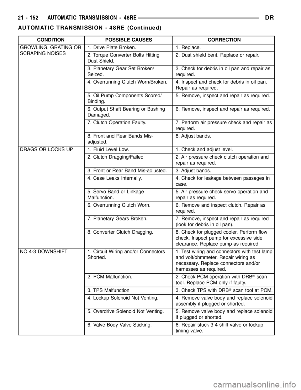
CONDITION POSSIBLE CAUSES CORRECTION
GROWLING, GRATING OR
SCRAPING NOISES1. Drive Plate Broken. 1. Replace.
2. Torque Converter Bolts Hitting
Dust Shield.2. Dust shield bent. Replace or repair.
3. Planetary Gear Set Broken/
Seized.3. Check for debris in oil pan and repair as
required.
4. Overrunning Clutch Worn/Broken. 4. Inspect and check for debris in oil pan.
Repair as required.
5. Oil Pump Components Scored/
Binding.5. Remove, inspect and repair as required.
6. Output Shaft Bearing or Bushing
Damaged.6. Remove, inspect and repair as required.
7. Clutch Operation Faulty. 7. Perform air pressure check and repair as
required.
8. Front and Rear Bands Mis-
adjusted.8. Adjust bands.
DRAGS OR LOCKS UP 1. Fluid Level Low. 1. Check and adjust level.
2. Clutch Dragging/Failed 2. Air pressure check clutch operation and
repair as required.
3. Front or Rear Band Mis-adjusted. 3. Adjust bands.
4. Case Leaks Internally. 4. Check for leakage between passages in
case.
5. Servo Band or Linkage
Malfunction.5. Air pressure check servo operation and
repair as required.
6. Overrunning Clutch Worn. 6. Remove and inspect clutch. Repair as
required.
7. Planetary Gears Broken. 7. Remove, inspect and repair as required
(look for debris in oil pan).
8. Converter Clutch Dragging. 8. Check for plugged cooler. Perform flow
check. Inspect pump for excessive side
clearance. Replace pump as required.
NO 4-3 DOWNSHIFT 1. Circuit Wiring and/or Connectors
Shorted.1. Test wiring and connectors with test lamp
and volt/ohmmeter. Repair wiring as
necessary. Replace connectors and/or
harnesses as required.
2. PCM Malfunction. 2. Check PCM operation with DRBTscan
tool. Replace PCM only if faulty.
3. TPS Malfunction 3. Check TPS with DRBTscan tool at PCM.
4. Lockup Solenoid Not Venting. 4. Remove valve body and replace solenoid
assembly if plugged or shorted.
5. Overdrive Solenoid Not Venting. 5. Remove valve body and replace solenoid
if plugged or shorted.
6. Valve Body Valve Sticking. 6. Repair stuck 3-4 shift valve or lockup
timing valve.
21 - 152 AUTOMATIC TRANSMISSION - 48REDR
AUTOMATIC TRANSMISSION - 48RE (Continued)
Page 1858 of 2627

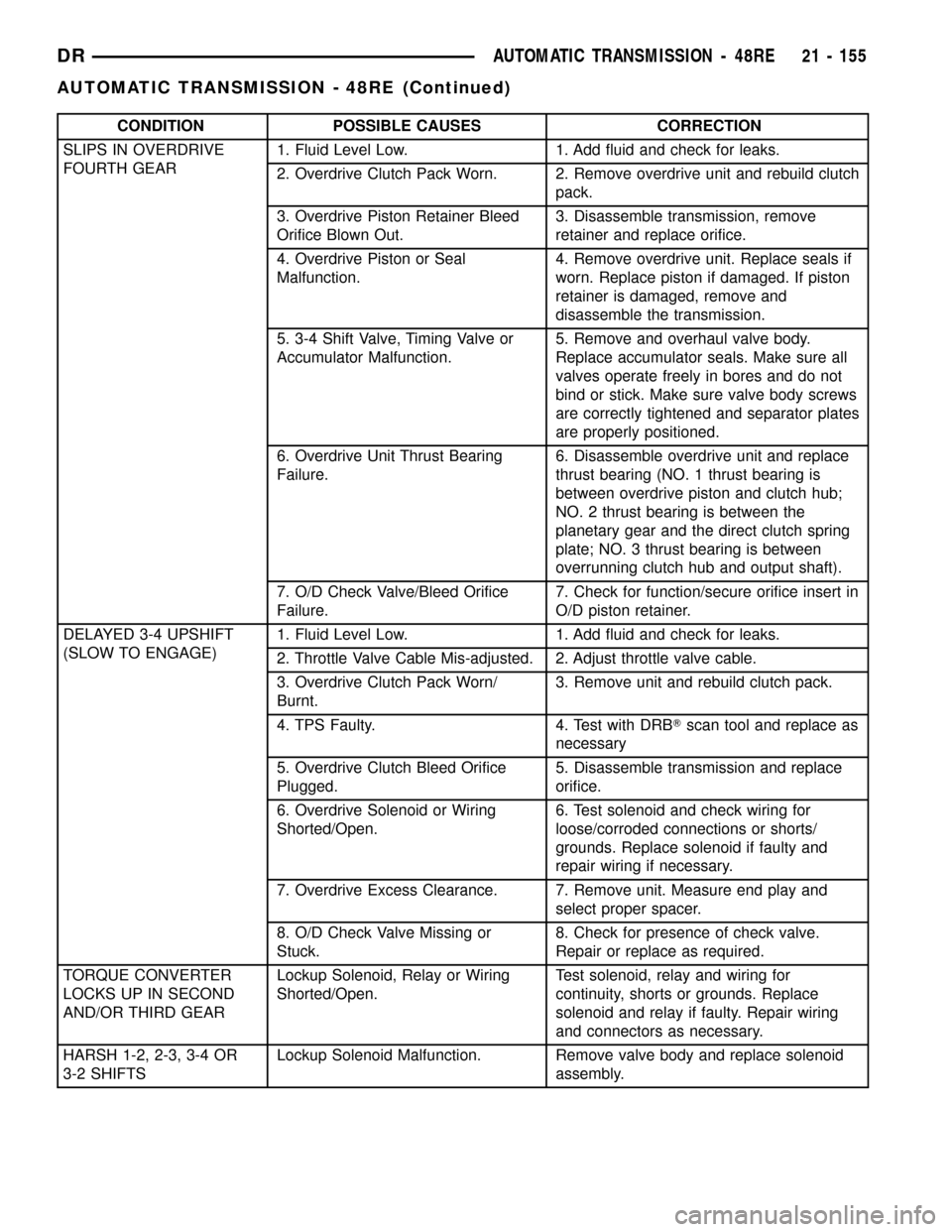
CONDITION POSSIBLE CAUSES CORRECTION
SLIPS IN OVERDRIVE
FOURTH GEAR1. Fluid Level Low. 1. Add fluid and check for leaks.
2. Overdrive Clutch Pack Worn. 2. Remove overdrive unit and rebuild clutch
pack.
3. Overdrive Piston Retainer Bleed
Orifice Blown Out.3. Disassemble transmission, remove
retainer and replace orifice.
4. Overdrive Piston or Seal
Malfunction.4. Remove overdrive unit. Replace seals if
worn. Replace piston if damaged. If piston
retainer is damaged, remove and
disassemble the transmission.
5. 3-4 Shift Valve, Timing Valve or
Accumulator Malfunction.5. Remove and overhaul valve body.
Replace accumulator seals. Make sure all
valves operate freely in bores and do not
bind or stick. Make sure valve body screws
are correctly tightened and separator plates
are properly positioned.
6. Overdrive Unit Thrust Bearing
Failure.6. Disassemble overdrive unit and replace
thrust bearing (NO. 1 thrust bearing is
between overdrive piston and clutch hub;
NO. 2 thrust bearing is between the
planetary gear and the direct clutch spring
plate; NO. 3 thrust bearing is between
overrunning clutch hub and output shaft).
7. O/D Check Valve/Bleed Orifice
Failure.7. Check for function/secure orifice insert in
O/D piston retainer.
DELAYED 3-4 UPSHIFT
(SLOW TO ENGAGE)1. Fluid Level Low. 1. Add fluid and check for leaks.
2. Throttle Valve Cable Mis-adjusted. 2. Adjust throttle valve cable.
3. Overdrive Clutch Pack Worn/
Burnt.3. Remove unit and rebuild clutch pack.
4. TPS Faulty. 4. Test with DRBTscan tool and replace as
necessary
5. Overdrive Clutch Bleed Orifice
Plugged.5. Disassemble transmission and replace
orifice.
6. Overdrive Solenoid or Wiring
Shorted/Open.6. Test solenoid and check wiring for
loose/corroded connections or shorts/
grounds. Replace solenoid if faulty and
repair wiring if necessary.
7. Overdrive Excess Clearance. 7. Remove unit. Measure end play and
select proper spacer.
8. O/D Check Valve Missing or
Stuck.8. Check for presence of check valve.
Repair or replace as required.
TORQUE CONVERTER
LOCKS UP IN SECOND
AND/OR THIRD GEARLockup Solenoid, Relay or Wiring
Shorted/Open.Test solenoid, relay and wiring for
continuity, shorts or grounds. Replace
solenoid and relay if faulty. Repair wiring
and connectors as necessary.
HARSH 1-2, 2-3, 3-4 OR
3-2 SHIFTSLockup Solenoid Malfunction. Remove valve body and replace solenoid
assembly.
DRAUTOMATIC TRANSMISSION - 48RE 21 - 155
AUTOMATIC TRANSMISSION - 48RE (Continued)
Page 1870 of 2627

assembled. Verify that thrust washers, thrust plates
and seal rings are correctly positioned.
The planetary geartrain, front/rear clutch assem-
blies and oil pump are all much easier to install
when the transmission case is upright. Either tilt the
case upward with wood blocks, or cut a hole in the
bench large enough for the intermediate shaft and
rear support. Then lower the shaft and support into
the hole and support the rear of the case directly on
the bench.
FRONT/REAR SERVO
(1) Lubricate rear servo piston seal with ATF +4.
Lubricate servo bore in case with ATF +4.
(2) Install rear servo piston in case. Position piston
at slight angle to bore and insert piston with twisting
motion (Fig. 40).
(3) Install rear servo spring and retainer in case
bore (Fig. 41). Be sure spring is seated on piston.
(4) Compress rear servo piston with C-clamp or
Valve Spring Compressor C-3422-B and install servo
piston snap-ring (Fig. 42).
(5) Lubricate front servo piston components and
servo bore in case with transmission fluid.
(6) Install front servo piston in bore. Carefully
ªrunº small, suitable tool around piston ring to press
it back into groove and ease installation (Fig. 43).
Rotate piston into bore at same time. Rock piston
slightly to ease piston ring past snap-ring groove and
into bore.
Fig. 40 Rear Servo Piston
1 - REAR SERVO PISTON
Fig. 41 Rear Servo Piston Spring And Retainer
1 - PISTON SPRING
2 - REAR SERVO PISTON
3 - SPRING RETAINER
Fig. 42 Rear Servo Snap Ring
1 - TOOL C-4470
2 - C-CLAMP
3 - REAR SERVO SPRING RETAINER
4 - RETAINER SNAP-RING
DRAUTOMATIC TRANSMISSION - 48RE 21 - 167
AUTOMATIC TRANSMISSION - 48RE (Continued)