1998 DODGE RAM 1500 Reverse
[x] Cancel search: ReversePage 1854 of 2627

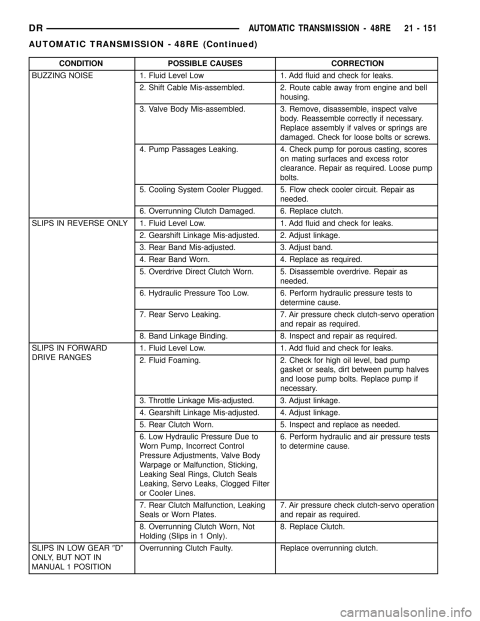
CONDITION POSSIBLE CAUSES CORRECTION
BUZZING NOISE 1. Fluid Level Low 1. Add fluid and check for leaks.
2. Shift Cable Mis-assembled. 2. Route cable away from engine and bell
housing.
3. Valve Body Mis-assembled. 3. Remove, disassemble, inspect valve
body. Reassemble correctly if necessary.
Replace assembly if valves or springs are
damaged. Check for loose bolts or screws.
4. Pump Passages Leaking. 4. Check pump for porous casting, scores
on mating surfaces and excess rotor
clearance. Repair as required. Loose pump
bolts.
5. Cooling System Cooler Plugged. 5. Flow check cooler circuit. Repair as
needed.
6. Overrunning Clutch Damaged. 6. Replace clutch.
SLIPS IN REVERSE ONLY 1. Fluid Level Low. 1. Add fluid and check for leaks.
2. Gearshift Linkage Mis-adjusted. 2. Adjust linkage.
3. Rear Band Mis-adjusted. 3. Adjust band.
4. Rear Band Worn. 4. Replace as required.
5. Overdrive Direct Clutch Worn. 5. Disassemble overdrive. Repair as
needed.
6. Hydraulic Pressure Too Low. 6. Perform hydraulic pressure tests to
determine cause.
7. Rear Servo Leaking. 7. Air pressure check clutch-servo operation
and repair as required.
8. Band Linkage Binding. 8. Inspect and repair as required.
SLIPS IN FORWARD
DRIVE RANGES1. Fluid Level Low. 1. Add fluid and check for leaks.
2. Fluid Foaming. 2. Check for high oil level, bad pump
gasket or seals, dirt between pump halves
and loose pump bolts. Replace pump if
necessary.
3. Throttle Linkage Mis-adjusted. 3. Adjust linkage.
4. Gearshift Linkage Mis-adjusted. 4. Adjust linkage.
5. Rear Clutch Worn. 5. Inspect and replace as needed.
6. Low Hydraulic Pressure Due to
Worn Pump, Incorrect Control
Pressure Adjustments, Valve Body
Warpage or Malfunction, Sticking,
Leaking Seal Rings, Clutch Seals
Leaking, Servo Leaks, Clogged Filter
or Cooler Lines.6. Perform hydraulic and air pressure tests
to determine cause.
7. Rear Clutch Malfunction, Leaking
Seals or Worn Plates.7. Air pressure check clutch-servo operation
and repair as required.
8. Overrunning Clutch Worn, Not
Holding (Slips in 1 Only).8. Replace Clutch.
SLIPS IN LOW GEAR9D9
ONLY, BUT NOT IN
MANUAL 1 POSITIONOverrunning Clutch Faulty. Replace overrunning clutch.
DRAUTOMATIC TRANSMISSION - 48RE 21 - 151
AUTOMATIC TRANSMISSION - 48RE (Continued)
Page 1859 of 2627

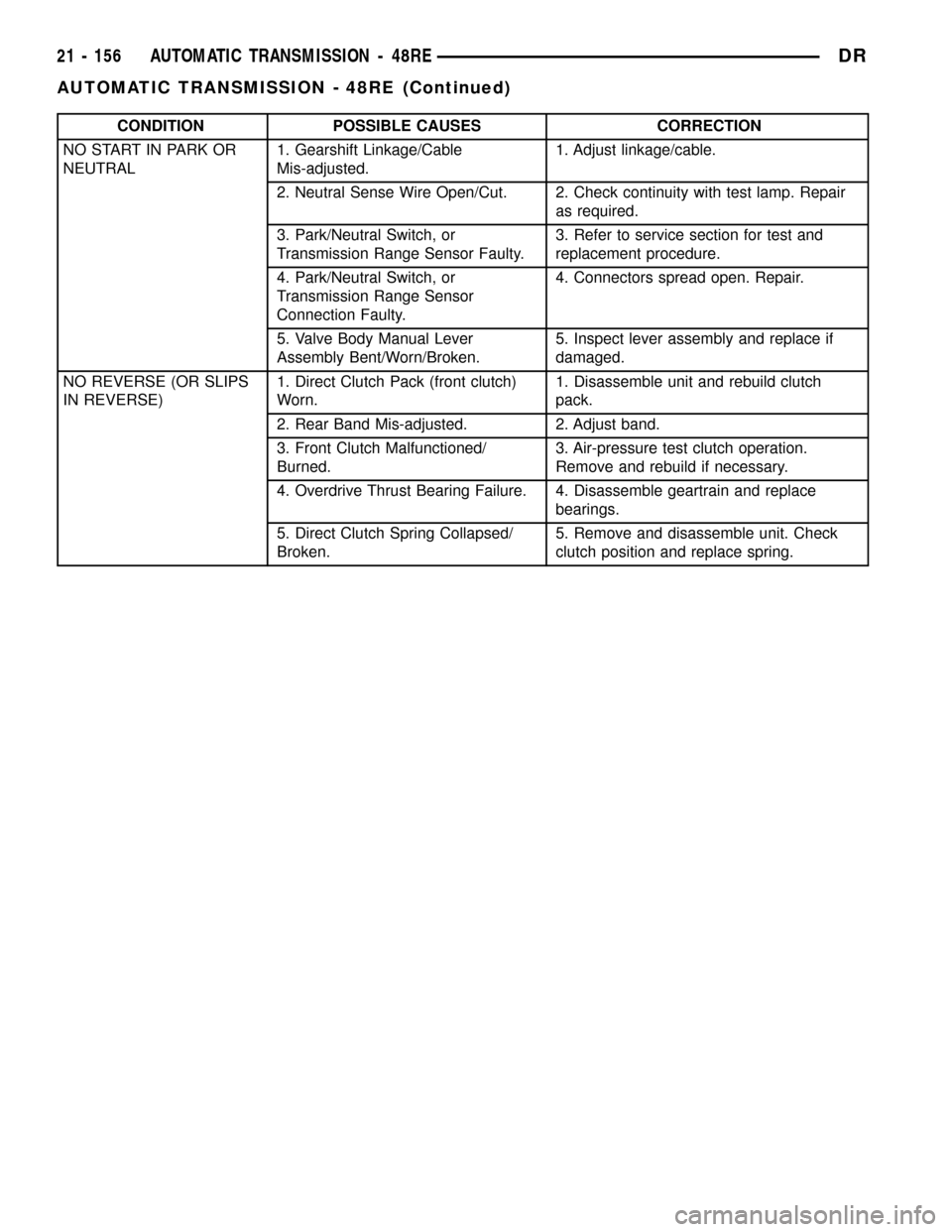
CONDITION POSSIBLE CAUSES CORRECTION
NO START IN PARK OR
NEUTRAL1. Gearshift Linkage/Cable
Mis-adjusted.1. Adjust linkage/cable.
2. Neutral Sense Wire Open/Cut. 2. Check continuity with test lamp. Repair
as required.
3. Park/Neutral Switch, or
Transmission Range Sensor Faulty.3. Refer to service section for test and
replacement procedure.
4. Park/Neutral Switch, or
Transmission Range Sensor
Connection Faulty.4. Connectors spread open. Repair.
5. Valve Body Manual Lever
Assembly Bent/Worn/Broken.5. Inspect lever assembly and replace if
damaged.
NO REVERSE (OR SLIPS
IN REVERSE)1. Direct Clutch Pack (front clutch)
Worn.1. Disassemble unit and rebuild clutch
pack.
2. Rear Band Mis-adjusted. 2. Adjust band.
3. Front Clutch Malfunctioned/
Burned.3. Air-pressure test clutch operation.
Remove and rebuild if necessary.
4. Overdrive Thrust Bearing Failure. 4. Disassemble geartrain and replace
bearings.
5. Direct Clutch Spring Collapsed/
Broken.5. Remove and disassemble unit. Check
clutch position and replace spring.
21 - 156 AUTOMATIC TRANSMISSION - 48REDR
AUTOMATIC TRANSMISSION - 48RE (Continued)
Page 1867 of 2627

(22) Remove thrust plate from intermediate shaft
hub (Fig. 32).
(23) Remove intermediate shaft-planetary
geartrain assembly (Fig. 33).
(24) Loosen rear band locknut and loosen adjust-
ing screw 3-4 turns.
(25) Remove snap-ring that retains low-reverse
drum on overdrive piston retainer hub (Fig. 34).
(26) Slide low-reverse drum and thrust washer off
piston retainer hub and out of rear band (Fig. 35).
Fig. 35 Low-Reverse Drum And Thrust Washer
1 - LOW-REVERSE DRUM
2 - SPOTFACE FOR WASHER
3 - THRUST WASHER
Fig. 32 Intermediate Shaft Thrust Plate
1 - SHAFT THRUST PLATE
2 - INTERMEDIATE SHAFT PILOT HUB
Fig. 33 Intermediate Shaft And Planetary Geartrain
1 - INTERMEDIATE SHAFT AND PLANETARY GEAR TRAIN
ASSEMBLY
Fig. 34 Low-Reverse Drum Snap-Ring
1 - LOW-REVERSE DRUM
2 - TABBED WASHER
3 - SNAP-RING
21 - 164 AUTOMATIC TRANSMISSION - 48REDR
AUTOMATIC TRANSMISSION - 48RE (Continued)
Page 1868 of 2627

(27) Note that overrunning clutch race will remain
on splines of low-reverse drum after removal (Fig.
36).The race is a permanent press fit on the
hub splines. Do not attempt to remove the race.
(28) Remove overrunning clutch assembly (Fig.
37). Assembly can be removed without displacing
rollers and springs if care is exercised. Note position
of rollers and springs for assembly reference.
(29) Remove rear band adjusting lever and reac-
tion pin.
(30) Remove rear band.
(31) Compress front servo rod guide with large
C-clamp and Tool C-4470, or Compressor Tool
C-3422-B (Fig. 38). Compress guide only enough to
permit snap-ring removal (about 1/8 in.).
(32) Remove servo piston snap-ring (Fig. 38).
Unseat one end of ring. Then carefully work removal
tool around back of ring until free of ring groove.
Exercise caution when removing snap-ring.
Servo bore can be scratched or nicked if care is
not exercised.
Fig. 38 Front Servo Retaining Snap-Ring
1 - C-CLAMP
2 - FRONT SERVO ROD GUIDE
3 - SNAP-RING
4 - TOOL C-4470
Fig. 36 Overrunning Clutch Race Position On
Low-Reverse Drum
1 - OVERRUNNING CLUTCH RACE
2 - LOW-REVERSE DRUM
Fig. 37 Overrunning Clutch
1 - CLUTCH CAM
2 - OVERRUNNING CLUTCH ASSEMBLY
DRAUTOMATIC TRANSMISSION - 48RE 21 - 165
AUTOMATIC TRANSMISSION - 48RE (Continued)
Page 1871 of 2627

(7) Bottom front servo piston in bore and install
servo spring.
(8) Install front servo piston rod guide as follows:
(a) Place Tool SP-5560 (or similar size tool) on
guide and position C-clamp on tool and case (Fig.
44).
(b) Slowly compress rod guide while simulta-
neously easing seal ring into bore with suitable
tool.
(9) Install rod guide snap-ring (Fig. 44).
OVERRUNNING CLUTCH, REAR BAND, AND
LOW-REVERSE DRUM
(1) Install overrunning clutch components if not
yet installed.
(2) Position rear band reaction pin and band in
case. Be sure that the twin lugs on the band are
seated against the reaction pin.
(3) Install low-reverse drum. Slide drum through
rear band, onto piston retainer hub and into engage-
ment with overrunning clutch and race.
(4) Install thrust washer in low-reverse drum spot-
face (Fig. 45). Use petroleum jelly to hold washer in
place.
(5) Install snap-ring that secures low-reverse drum
to piston retainer hub (Fig. 45).
(6) Insert the rear band pivot pin part way into
the case.(7) Install rear band adjusting lever and pivot pin.
Be sure lever and the single lug on the band are
aligned and engaged before seating band pivot pin in
case.
Fig. 43 Front Servo Piston
1 - USE SUITABLE TOOL TO HELP SEAT PISTON RING
2 - FRONT SERVO PISTON
Fig. 44 Front Servo Rod Guide And Snap Ring
1 - C-CLAMP
2 - ROD GUIDE
3 - SMALL SCREWDRIVER
4 - ROD GUIDE SNAP-RING
5 - TOOL SP-5560
Fig. 45 Low-Reverse Drum Snap Ring
1 - LOW-REVERSE DRUM
2 - TABBED WASHER
3 - SNAP-RING
21 - 168 AUTOMATIC TRANSMISSION - 48REDR
AUTOMATIC TRANSMISSION - 48RE (Continued)
Page 1876 of 2627

(a) Start park rod into park pawl. If rod will not
slide past park pawl, pawl is engaged in park gear.
Rotate overdrive output shaft with suitable size 12
point socket; this will free pawl and allow rod to
engage.
(b) Align and seat valve body on case. Be sure
manual lever shaft and overdrive connector are
fully seated in case.
(c) Install and start all valve body attaching
bolts by hand. Then tighten bolts evenly, in a diag-
onal pattern to 12 N´m (105 in. lbs.) torque.Do
not overtighten valve body bolts. This could
result in distortion and cross leakage after
installation..
(5) Install new filter on valve body. Tighten filter
screws to 4 N´m (35 in. lbs.).
CAUTION: If the condition of the transmission
before the overhaul procedure caused excessive
metallic or fiber contamination in the fluid, replace
the torque converter and reverse flush the cooler(s)
and cooler lines. Fluid contamination and transmis-
sion failure can result if not done.(6) Move the transmission manual shaft lever to
the manual LOW position.
(7) Install the TRS mounting bracket into the
transmission case. Using Adapter 8581 (Fig. 60),
tighten the mounting bracket to 34 N´m (300 in.lbs.).
(8) Install the TRS (Fig. 61) into the mounting
bracket with the wiring connector facing the front of
the transmission.
Fig. 58 Accumulator Piston And Springs
1 - ACCUMULATOR PISTON
2 - OUTER SPRING
3 - INNER SPRING
Fig. 59 Manual Lever Shaft Seal
1 - 15/1688SOCKET
2 - SEAL
Fig. 60 Tighten the TRS Mounting Bracket
1 - SOLENOID CASE CONNECTOR
2 - TRS MOUNTING BRACKET
3 - ADAPTER 8581
Fig. 61 Remove Transmission Range Sensor
1 - SOLENOID CASE CONNECTOR
2 - TRS MOUNTING BRACKET
3 - TRANSMISSION RANGE SENSOR
DRAUTOMATIC TRANSMISSION - 48RE 21 - 173
AUTOMATIC TRANSMISSION - 48RE (Continued)
Page 1877 of 2627

(9) Install the two screws to hold the TRS to the
mounting bracket. Tighten the screws to 5 N´m (45
in.lbs.).
(10) Verify proper sensor operation (Fig. 62).
(11) Move the transmission manual shaft lever to
the PARK position.
(12) Install torque converter. Use C-clamp or metal
strap to hold converter in place for installation.
BAND ADJUSTMENT AND FINAL
(1) Adjust front and rear bands as follows:
(a) Loosen locknut on each band adjusting screw
4-5 turns.
(b) Tighten both adjusting screws to 8 N´m (72
in. lbs.).
(c) Back off front band adjusting screw 1-3/4
turns.
(d) Back off rear band adjusting screw 3 turns.
(e) Hold each adjusting screw in position and
tighten locknut to 34 N´m (25 ft. lbs.) torque.
(2) Install magnet in oil pan. Magnet seats on
small protrusion at corner of pan.
(3) Position new oil pan gasket on case and install
oil pan. Tighten pan bolts to 13.6 N´m (125 in. lbs.).
(4) Install throttle valve and shift selector levers
on valve body manual lever shaft.
(5) Apply small quantity of dielectric grease to ter-
minal pins of solenoid case connector and neutral
switch.
(6) Fill transmission with recommended fluid.
INSTALLATION
(1) Check torque converter hub inner and outer
diameters and hub drive notches for sharp edgesburrs, scratches, or nicks. Polish the hub and notches
with 320/400 grit paper and crocus cloth if necessary.
The hub must be smooth to avoid damaging pump
seal at installation.
(2) Lubricate pocket in the rear oil pump seal lip
with transmission fluid.
(3) Lubricate converter pilot hub of the crankshaft
with a light coating of MopartHigh Temp Grease.
(4) Align and install converter in oil pump.
(5) Carefully insert converter in oil pump. Then
rotate converter back and forth until fully seated in
pump gears.
(6) Check converter seating with steel scale and
straightedge (Fig. 63). Surface of converter lugs
should be 19mm (0.75 in.) to rear of straightedge
when converter is fully seated.
(7) Temporarily secure converter with C-clamp.
(8) Position transmission on jack and secure it
with chains.
(9) Check condition of converter driveplate.
Replace the plate if cracked, distorted or damaged.
Also be sure transmission dowel pins are seated
in engine block and protrude far enough to
hold transmission in alignment.
(10) Raise transmission and align converter with
drive plate and converter housing with engine block.
(11) Move transmission forward. Then raise, lower
or tilt transmission to align converter housing with
engine block dowels.
(12) Carefully work transmission forward and over
engine block dowels until converter hub is seated in
crankshaft.
Fig. 62 Transmission Range Sensor Operation
1 - NEUTRAL CONTACT
2 - MANUAL LEVER AND SENSOR PLUNGER IN REVERSE
POSITION
3 - PARK CONTACT
4 - TRANSMISSION RANGE SENSOR
Fig. 63 Checking Converter Seating - Typical
1 - SCALE
2 - STRAIGHTEDGE
21 - 174 AUTOMATIC TRANSMISSION - 48REDR
AUTOMATIC TRANSMISSION - 48RE (Continued)
Page 1881 of 2627

HYDRAULIC FLOW IN REVERSE
21 - 178 AUTOMATIC TRANSMISSION - 48REDR
AUTOMATIC TRANSMISSION - 48RE (Continued)